EP1249624A2 - Roller bearing with a retainer having voids for grease container - Google Patents
Roller bearing with a retainer having voids for grease container Download PDFInfo
- Publication number
- EP1249624A2 EP1249624A2 EP02252578A EP02252578A EP1249624A2 EP 1249624 A2 EP1249624 A2 EP 1249624A2 EP 02252578 A EP02252578 A EP 02252578A EP 02252578 A EP02252578 A EP 02252578A EP 1249624 A2 EP1249624 A2 EP 1249624A2
- Authority
- EP
- European Patent Office
- Prior art keywords
- retainer
- roller bearing
- rollers
- notches
- outer race
- Prior art date
- Legal status (The legal status is an assumption and is not a legal conclusion. Google has not performed a legal analysis and makes no representation as to the accuracy of the status listed.)
- Granted
Links
Images


Classifications
-
- F—MECHANICAL ENGINEERING; LIGHTING; HEATING; WEAPONS; BLASTING
- F16—ENGINEERING ELEMENTS AND UNITS; GENERAL MEASURES FOR PRODUCING AND MAINTAINING EFFECTIVE FUNCTIONING OF MACHINES OR INSTALLATIONS; THERMAL INSULATION IN GENERAL
- F16C—SHAFTS; FLEXIBLE SHAFTS; ELEMENTS OR CRANKSHAFT MECHANISMS; ROTARY BODIES OTHER THAN GEARING ELEMENTS; BEARINGS
- F16C33/00—Parts of bearings; Special methods for making bearings or parts thereof
- F16C33/30—Parts of ball or roller bearings
- F16C33/66—Special parts or details in view of lubrication
-
- F—MECHANICAL ENGINEERING; LIGHTING; HEATING; WEAPONS; BLASTING
- F16—ENGINEERING ELEMENTS AND UNITS; GENERAL MEASURES FOR PRODUCING AND MAINTAINING EFFECTIVE FUNCTIONING OF MACHINES OR INSTALLATIONS; THERMAL INSULATION IN GENERAL
- F16C—SHAFTS; FLEXIBLE SHAFTS; ELEMENTS OR CRANKSHAFT MECHANISMS; ROTARY BODIES OTHER THAN GEARING ELEMENTS; BEARINGS
- F16C33/00—Parts of bearings; Special methods for making bearings or parts thereof
- F16C33/72—Sealings
- F16C33/76—Sealings of ball or roller bearings
- F16C33/78—Sealings of ball or roller bearings with a diaphragm, disc, or ring, with or without resilient members
- F16C33/7893—Sealings of ball or roller bearings with a diaphragm, disc, or ring, with or without resilient members mounted to a cage or integral therewith
-
- F—MECHANICAL ENGINEERING; LIGHTING; HEATING; WEAPONS; BLASTING
- F16—ENGINEERING ELEMENTS AND UNITS; GENERAL MEASURES FOR PRODUCING AND MAINTAINING EFFECTIVE FUNCTIONING OF MACHINES OR INSTALLATIONS; THERMAL INSULATION IN GENERAL
- F16C—SHAFTS; FLEXIBLE SHAFTS; ELEMENTS OR CRANKSHAFT MECHANISMS; ROTARY BODIES OTHER THAN GEARING ELEMENTS; BEARINGS
- F16C13/00—Rolls, drums, discs, or the like; Bearings or mountings therefor
- F16C13/006—Guiding rollers, wheels or the like, formed by or on the outer element of a single bearing or bearing unit, e.g. two adjacent bearings, whose ratio of length to diameter is generally less than one
-
- F—MECHANICAL ENGINEERING; LIGHTING; HEATING; WEAPONS; BLASTING
- F16—ENGINEERING ELEMENTS AND UNITS; GENERAL MEASURES FOR PRODUCING AND MAINTAINING EFFECTIVE FUNCTIONING OF MACHINES OR INSTALLATIONS; THERMAL INSULATION IN GENERAL
- F16C—SHAFTS; FLEXIBLE SHAFTS; ELEMENTS OR CRANKSHAFT MECHANISMS; ROTARY BODIES OTHER THAN GEARING ELEMENTS; BEARINGS
- F16C19/00—Bearings with rolling contact, for exclusively rotary movement
- F16C19/22—Bearings with rolling contact, for exclusively rotary movement with bearing rollers essentially of the same size in one or more circular rows, e.g. needle bearings
- F16C19/44—Needle bearings
- F16C19/46—Needle bearings with one row or needles
-
- F—MECHANICAL ENGINEERING; LIGHTING; HEATING; WEAPONS; BLASTING
- F16—ENGINEERING ELEMENTS AND UNITS; GENERAL MEASURES FOR PRODUCING AND MAINTAINING EFFECTIVE FUNCTIONING OF MACHINES OR INSTALLATIONS; THERMAL INSULATION IN GENERAL
- F16C—SHAFTS; FLEXIBLE SHAFTS; ELEMENTS OR CRANKSHAFT MECHANISMS; ROTARY BODIES OTHER THAN GEARING ELEMENTS; BEARINGS
- F16C21/00—Combinations of sliding-contact bearings with ball or roller bearings, for exclusively rotary movement
-
- F—MECHANICAL ENGINEERING; LIGHTING; HEATING; WEAPONS; BLASTING
- F16—ENGINEERING ELEMENTS AND UNITS; GENERAL MEASURES FOR PRODUCING AND MAINTAINING EFFECTIVE FUNCTIONING OF MACHINES OR INSTALLATIONS; THERMAL INSULATION IN GENERAL
- F16C—SHAFTS; FLEXIBLE SHAFTS; ELEMENTS OR CRANKSHAFT MECHANISMS; ROTARY BODIES OTHER THAN GEARING ELEMENTS; BEARINGS
- F16C33/00—Parts of bearings; Special methods for making bearings or parts thereof
- F16C33/30—Parts of ball or roller bearings
- F16C33/46—Cages for rollers or needles
- F16C33/49—Cages for rollers or needles comb-shaped
- F16C33/491—Cages for rollers or needles comb-shaped applied as pairs for retaining both ends of the rollers or needles
-
- F—MECHANICAL ENGINEERING; LIGHTING; HEATING; WEAPONS; BLASTING
- F16—ENGINEERING ELEMENTS AND UNITS; GENERAL MEASURES FOR PRODUCING AND MAINTAINING EFFECTIVE FUNCTIONING OF MACHINES OR INSTALLATIONS; THERMAL INSULATION IN GENERAL
- F16C—SHAFTS; FLEXIBLE SHAFTS; ELEMENTS OR CRANKSHAFT MECHANISMS; ROTARY BODIES OTHER THAN GEARING ELEMENTS; BEARINGS
- F16C33/00—Parts of bearings; Special methods for making bearings or parts thereof
- F16C33/30—Parts of ball or roller bearings
- F16C33/46—Cages for rollers or needles
- F16C33/49—Cages for rollers or needles comb-shaped
- F16C33/494—Massive or moulded comb cages
- F16C33/495—Massive or moulded comb cages formed as one piece cages, i.e. monoblock comb cages
- F16C33/498—Massive or moulded comb cages formed as one piece cages, i.e. monoblock comb cages made from plastic, e.g. injection moulded comb cages
-
- F—MECHANICAL ENGINEERING; LIGHTING; HEATING; WEAPONS; BLASTING
- F16—ENGINEERING ELEMENTS AND UNITS; GENERAL MEASURES FOR PRODUCING AND MAINTAINING EFFECTIVE FUNCTIONING OF MACHINES OR INSTALLATIONS; THERMAL INSULATION IN GENERAL
- F16C—SHAFTS; FLEXIBLE SHAFTS; ELEMENTS OR CRANKSHAFT MECHANISMS; ROTARY BODIES OTHER THAN GEARING ELEMENTS; BEARINGS
- F16C33/00—Parts of bearings; Special methods for making bearings or parts thereof
- F16C33/30—Parts of ball or roller bearings
- F16C33/66—Special parts or details in view of lubrication
- F16C33/6603—Special parts or details in view of lubrication with grease as lubricant
- F16C33/6607—Retaining the grease in or near the bearing
- F16C33/6614—Retaining the grease in or near the bearing in recesses or cavities provided in retainers, races or rolling elements
-
- F—MECHANICAL ENGINEERING; LIGHTING; HEATING; WEAPONS; BLASTING
- F16—ENGINEERING ELEMENTS AND UNITS; GENERAL MEASURES FOR PRODUCING AND MAINTAINING EFFECTIVE FUNCTIONING OF MACHINES OR INSTALLATIONS; THERMAL INSULATION IN GENERAL
- F16C—SHAFTS; FLEXIBLE SHAFTS; ELEMENTS OR CRANKSHAFT MECHANISMS; ROTARY BODIES OTHER THAN GEARING ELEMENTS; BEARINGS
- F16C2226/00—Joining parts; Fastening; Assembling or mounting parts
- F16C2226/30—Material joints
- F16C2226/36—Material joints by welding
-
- F—MECHANICAL ENGINEERING; LIGHTING; HEATING; WEAPONS; BLASTING
- F16—ENGINEERING ELEMENTS AND UNITS; GENERAL MEASURES FOR PRODUCING AND MAINTAINING EFFECTIVE FUNCTIONING OF MACHINES OR INSTALLATIONS; THERMAL INSULATION IN GENERAL
- F16C—SHAFTS; FLEXIBLE SHAFTS; ELEMENTS OR CRANKSHAFT MECHANISMS; ROTARY BODIES OTHER THAN GEARING ELEMENTS; BEARINGS
- F16C29/00—Bearings for parts moving only linearly
- F16C29/04—Ball or roller bearings
- F16C29/045—Ball or roller bearings having rolling elements journaled in one of the moving parts
Definitions
- the present invention relates to a roller bearing, and more particularly, a roller bearing having a plurality of rollers circumferentially disposed and each rotatably supported by a retainer.
- a roller bearing includes a plurality of circumferentially located rollers and a retainer with a plurality of supporting holes adapted to support the rollers rotatably.
- the retainer typically has an outer race and/or an inner race.
- the present invention has been made to eliminate these problems and its object is to provide a roller bearing having an adequate lubricating function even in the case where the bearing is composed of smaller rollers or the bearing has a smaller outer diameter.
- a roller bearing of the present invention includes N pieces of rollers disposed circumferentially and parallel to each other, and a retainer adapted to support the rollers rotatably.
- Each roller has a first and second end portion located axially away from each other.
- the retainer includes a first, generally cylindrical retainer member having N pieces of first notches adapted to rotatably support the first end portion of each roller and a second, generally cylindrical retainer member that is located axially away from and opposite the first retainer member and that has N pieces of second notches adapted to rotatably support the second end portion of each roller.
- a plurality of voids are provided to form grease containing spaces between the oppositely disposed first and second notches and the circumferentially adjacent, oppositely disposed first and second notches between the first and second retainer members.
- the retainer is formed of the first and second retainer members contraposed and located away from each other, and voids for grease are formed between circumferentially adjacent notches of these retainer members, even in the case of a needle roller bearing having rollers of smaller diameters and a retainer of a thinner thickness, or a needle roller bearing with a smaller outer diameter and narrower spaces between the adjacent supporting holes, a grease containing space can be secured and thus, adequate lubricating function can be achieved.
- each roller can be securely lubricated with adequate amount of grease. Also, in this case, not an elongated aperture but a notch is formed in the first and second retainer member to receive each roller.
- each retainer member it can be formed using an axially movable mold. Therefore, a multiple mold can be deployed on the same plane in a molding unit of a forming machine, thereby reducing the cost of a mold and manufacturing cost.
- first and second retainer members When the first and second retainer members are connected to each other by n ( ⁇ N) pieces of connections provided at voids and (N-n) pieces of voids are formed between the first and second retainer members, the first and second retainer members can be formed integrally with each other through connections, thus facilitating assembly of a roller bearing.
- first and second retainer members and connections are preferably welded or fused by ultrasonic wave or the like, and alternatively, they may be integrated with each other by plastics molding.
- the outer race When a cylindrical outer race is further provided and opposite ends of the outer race are supported by the first and second retainer member, the outer race is located on an outer circumferential side of each void formed at adjacent rollers, thereby preventing grease from flying out of the void through centrifugal force. Also, an axial distance between the first and second retainer member can be maintained by the outer race, and the first and second retainer member and the outer race can be integrated with each other, thus facilitating assembly of a roller bearing.
- a lip portion of tapered cross section contacting the inner circumference of the outer race may be formed on the first and second retainer member.
- grease which is housed in a void between the first and second retainer members can be prevented from leaking out from the inner circumference of the outer race through a clearance between the opposite ends of the outer race and the first and second retainer members.
- An oil groove may be formed at a portion of the first and second retainer member contacting the outer race.
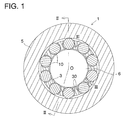
- FIG. 1 is a cross sectional view of a needle roller bearing according to an embodiment of the present invention, showing a cross section of FIG. 2 taken along line I - I.
- FIG. 2 is a longitudinal sectional view of FIG. 1 taken along line II - II.
- FIG. 3 is a side view of a portion of a needle roller bearing of the present invention, as viewed from line III - III of FIG. 1.
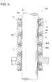
- FIG. 4 is a side view of a portion of a needle roller bearing according to another embodiment of the present invention.
- FIG. 5 is a sectional view of a column guide employing a needle roller bearing of FIG. 1.
- FIGS. 1 and 2 show a needle bearing according to an embodiment of the present invention.
- FIG. 1 is a cross sectional view of FIG. 2 taken along line I - I and
- FIG. 2 is a longitudinal sectional view of FIG. 1 taken along line II - II.
- a needle roller bearing 1 includes a plurality of needle-shaped rollers 10 disposed along a circumference and parallel to each other, and a first and second retainer member 2, 3 having a generally cylindrical shape and located axially away from and opposite each other.
- FIG. 3 is a side view of a portion of the needle roller bearing 1.
- the first retainer member 2 has a plurality of first notches 20 each rotatably supporting an end portion 10a of the roller 10.
- the second retainer member 3 has a plurality of second notches 30 each rotatably supporting the other end portion 10b of the roller 10. These notches 20, 30 are disposed opposite each other.
- a void 4 that forms a grease containing portion between adjacent rollers 10.
- a protrusion 22 is formed between adjacent notches 20 of the first retainer member 2, and similarly, a protrusion 32 is formed between adjacent notches 30 of the second retainer member 3.
- a void 4 is formed between these protrusions 22 and 32 oppositely disposed in an axial direction.
- the number of the voids 4 is the same as that of each of the notches 20, 30.
- a cylindrical outer race 5 is provided between the first and second retainer members 2, 3.
- the first and second retainer members 2, 3 are respectively formed with bosses 2a, 3a each supporting an end portion 50, 51 of the outer race 5.
- Lip portions 24, 34 each having a tapered cross section and contacting an inner circumferential surface 5a of the outer race 5 are formed at the bosses 2a, 3a.
- the outer circumferential surface 5b or cylindrical surface of the outer race 5 is formed straight. That is, a generating line of the cylindrical surface 5b is straight.
- the first and second retainer members 2, 3 respectively have central holes 2b, 3b into which a shaft 6 is inserted.
- An oil groove 26 is formed on a side surface of the first retainer member 2 and an oil groove 28 is formed on an end surface 2c of the first retainer member 2.
- an oil groove 36 is formed on a side surface of the second retainer member 3 and an oil groove 38 is formed on an end surface 3c of the second retainer member 3.
- side walls 15, 16 are respectively provided beside the first and second retainer members 2, 3. These side walls 15, 16 restrain axial movements of the first and second retainer members 2, 3, thereby preventing the needle roller bearing 1 from falling off the shaft 6.
- first and second retainer members 2, 3 and a plurality of voids 4 are formed between the adjacent rollers 10 to provide grease containers, especially in the case of a needle roller bearing with a thinner retainer, or with a very narrower space between the adjacent needle rollers and a smaller outer diameter, grease reservoir or container can be secured, and thus, an adequate lubricating function can be achieved.
- a grease container is formed not on the surface of the retainer but in the voids 4 where no other members exist between the retainer members 2 and 3, more grease can be directly applied on a rolling contact surface between the shaft 6 and each needle 10, thereby lubricating the rolling contact surface more adequately and securely.
- the outer race 5 positioned outside the voids 4 prevents grease in each void 4 from flying out of the void 4 through centrifugal force.
- the first and second retainer members 2, 3 are integrated with each other through the outer race 5, thus facilitating assembly of the needle roller bearing. Additionally, since the outer race 5 has a straight cylindrical face, working process of the outer race 5 becomes easier.
- each retainer member 2, 3 it can be formed using an axially movable mold. Therefore, a multiple mold can be deployed on the same plane in a molding unit of a forming machine, thereby reducing manufacturing cost.
- oil grooves 26, 36 formed on the side faces of the retainer members 2, 3 prevent wear to the side faces of the retainer members 2, 3 due to the difference of the rotational speed between the retainer members 2, 3 and the outer race 5.
- oil grooves 28, 38 formed on the end faces 2c, 3c of the retainer members 2, 3 prevent wear to the end faces 2c, 3c.
- first and second retainer members 2, 3 are completely separated and located away from each other, but the application of the present invention is not limited to this embodiment.
- the present invention also applies to another embodiment shown in FIG. 4.
- the same reference numerals indicate the same or corresponding portions of FIG. 3.
- the first retainer member 2 is partly connected to the second retainer member 3. That is, between the first and second retainer members 2, 3, voids 4 and connections 7 to connect the corresponding projections 22, 32 coexist.
- the number of voids 4 is (N-n).
- the first and second retainer members 2, 3 can be integrated with each other through connections 7, thereby facilitating assembly of a needle roller bearing.
- connection 7 is preferably formed by fusing or welding a connecting portion 29 of the first retainer member 2 to a corresponding connecting portion 39 of the second retainer member 3 through supersonic wave or the like.
- these connections 29, 39 may be formed integrally with each other through plastics molding.
- FIG. 5 shows a column guide employing the needle roller bearing 1 of the present invention.
- a column guide 100 includes an axially extending ram 8 of a solid cylindrical shape and a column 9 of a hollow cylindrical shape that receives the ram 8 and that is axially translatable relative to the ram 8.
- the column 9 is composed of a plurality of ring-shaped members 90 that are stacked axially and fixed to each other in a known manner such as bolts. On contact faces of the adjacent ring-shaped members 90, a plurality of recesses 90a disposed around the ram 8 are formed.
- the above-mentioned needle roller bearing 1 is housed in a space formed by the oppositely disposed recesses 90a of the adjacent ring-shaped members 90. In FIG. 5, the needle roller bearing 1 is shown in a simplified manner.
- Each shaft 6 of the needle roller bearing 1 extends in a direction perpendicular to the axis of the ram 8 and is supported by the ring-shaped member 90.
- the outer circumferential surface 5b of the outer race 5 is in contact with the outer circumferential surface 8a of the ram 8.
- the outer race 5 of the needle roller bearing 1 may have a cylindrical surface 5b of a concavely curved generating line.
- the outer circumferential surface 8a of the ram 8 is formed by a convexly curved surface with a smaller radius of curvature than a cylindrical surface 5b of the outer race 8, a contact area between the cylindrical surface 5b of the outer race 5 and the outer circumferential surface 8a of the ram 8 increases and surface pressure on the contact surface can be decreased, thereby improving wear resistance.
- the outer race 5 has a cylindrical surface 5b of a convexly curved generating line and the outer circumferential surface 8a of the ram 8 is formed by a concavely curved surface with a greater radius of curvature than a cylindrical surface 5b of the outer race 5, a contact area between the cylindrical surface 5b of the outer race 5 and the outer circumferential surface 8a of the ram 8 increases and surface pressure on the contact surface can be decreased, thereby improving wear resistance.
Landscapes
- Engineering & Computer Science (AREA)
- General Engineering & Computer Science (AREA)
- Mechanical Engineering (AREA)
- Rolling Contact Bearings (AREA)
Abstract
Description
- The present invention relates to a roller bearing, and more particularly, a roller bearing having a plurality of rollers circumferentially disposed and each rotatably supported by a retainer.
- Generally, a roller bearing includes a plurality of circumferentially located rollers and a retainer with a plurality of supporting holes adapted to support the rollers rotatably. The retainer typically has an outer race and/or an inner race. As a lubricating method of such a roller bearing, applying grease on the retainer, forming a recess as a grease container on the retainer, or oil drip or splash is conducted.
- However, in a roller bearing with smaller rollers, especially, in a needle roller bearing, since a thickness of a retainer is thinner and a distance between adjacent supporting holes of the retainer is narrower, it is difficult to form a recess as a grease container between adjacent supporting holes on a retainer. Particularly, in a needle roller bearing with a smaller outer diameter, since a distance between adjacent supporting holes of the retainer is much narrower, it is very difficult to form a recess as a grease container between adjacent supporting holes on a retainer.
- Therefore, a prior art roller bearing, especially with smaller rollers and a smaller outer diameter, could not be fully lubricated.
- The present invention has been made to eliminate these problems and its object is to provide a roller bearing having an adequate lubricating function even in the case where the bearing is composed of smaller rollers or the bearing has a smaller outer diameter.
- A roller bearing of the present invention includes N pieces of rollers disposed circumferentially and parallel to each other, and a retainer adapted to support the rollers rotatably. Each roller has a first and second end portion located axially away from each other. The retainer includes a first, generally cylindrical retainer member having N pieces of first notches adapted to rotatably support the first end portion of each roller and a second, generally cylindrical retainer member that is located axially away from and opposite the first retainer member and that has N pieces of second notches adapted to rotatably support the second end portion of each roller. A plurality of voids are provided to form grease containing spaces between the oppositely disposed first and second notches and the circumferentially adjacent, oppositely disposed first and second notches between the first and second retainer members.
- According to the present invention, since the retainer is formed of the first and second retainer members contraposed and located away from each other, and voids for grease are formed between circumferentially adjacent notches of these retainer members, even in the case of a needle roller bearing having rollers of smaller diameters and a retainer of a thinner thickness, or a needle roller bearing with a smaller outer diameter and narrower spaces between the adjacent supporting holes, a grease containing space can be secured and thus, adequate lubricating function can be achieved.
- Moreover, in this case, because a grease container is not formed concavely on the surface of the retainer but formed at a void where no other members exist between the first and second retainer members, grease can be directly applied to a rolling contact surface between an inner and outer race member and each roller. Thus, the rolling contact surface can be fully and securely lubricated.
- When the first and second retainer members are formed separately, N pieces of voids are provided between the first and second retainer members. In this case, since the same number of grease containers as rollers is formed, each roller can be securely lubricated with adequate amount of grease. Also, in this case, not an elongated aperture but a notch is formed in the first and second retainer member to receive each roller. Thus, in injection molding each retainer member, it can be formed using an axially movable mold. Therefore, a multiple mold can be deployed on the same plane in a molding unit of a forming machine, thereby reducing the cost of a mold and manufacturing cost.
- To the contrary, in forming a prior art retainer having a plurality of apertures to hold rollers, an inner mold disposed on an inner circumferential side and a plurality of outer molds disposed on an outer circumferential side and divided in a normal direction are required to compose a mold, and each outer mold needs to be translatable in a normal direction. Thus, the structure of a mold becomes complicated and the only one mold can be disposed at a mold unit of a forming machine to secure a travel space of the outer mold, thereby increasing the cost of a mold and a manufacturing cost.
- When the first and second retainer members are connected to each other by n (<N) pieces of connections provided at voids and (N-n) pieces of voids are formed between the first and second retainer members, the first and second retainer members can be formed integrally with each other through connections, thus facilitating assembly of a roller bearing. In addition, the first and second retainer members and connections are preferably welded or fused by ultrasonic wave or the like, and alternatively, they may be integrated with each other by plastics molding.
- When a cylindrical outer race is further provided and opposite ends of the outer race are supported by the first and second retainer member, the outer race is located on an outer circumferential side of each void formed at adjacent rollers, thereby preventing grease from flying out of the void through centrifugal force. Also, an axial distance between the first and second retainer member can be maintained by the outer race, and the first and second retainer member and the outer race can be integrated with each other, thus facilitating assembly of a roller bearing.
- A lip portion of tapered cross section contacting the inner circumference of the outer race may be formed on the first and second retainer member. In this case, by providing such a lip portion, grease which is housed in a void between the first and second retainer members can be prevented from leaking out from the inner circumference of the outer race through a clearance between the opposite ends of the outer race and the first and second retainer members.
- An oil groove may be formed at a portion of the first and second retainer member contacting the outer race. Thus, especially in an application where a shaft is fixed and an outer race is rotatable, wear to the retainers due to the difference of the rotational speeds between the retainer and the outer race can be prevented.
- For a more complete understanding of the invention, reference should be made to the embodiments illustrated in greater detail in the accompanying drawings and described below by way of examples of the invention. In the drawings, which are not to scale:
- FIG. 1 is a cross sectional view of a needle roller bearing according to an embodiment of the present invention, showing a cross section of FIG. 2 taken along line I - I.
- FIG. 2 is a longitudinal sectional view of FIG. 1 taken along line II - II.
- FIG. 3 is a side view of a portion of a needle roller bearing of the present invention, as viewed from line III - III of FIG. 1.
- FIG. 4 is a side view of a portion of a needle roller bearing according to another embodiment of the present invention.
- FIG. 5 is a sectional view of a column guide employing a needle roller bearing of FIG. 1.
- Referring now to the drawings, FIGS. 1 and 2 show a needle bearing according to an embodiment of the present invention. FIG. 1 is a cross sectional view of FIG. 2 taken along line I - I and FIG. 2 is a longitudinal sectional view of FIG. 1 taken along line II - II.
- As shown in FIGS. 1 and 2, a needle roller bearing 1 includes a plurality of needle-
shaped rollers 10 disposed along a circumference and parallel to each other, and a first andsecond retainer member - FIG. 3 is a side view of a portion of the needle roller bearing 1. The
first retainer member 2 has a plurality offirst notches 20 each rotatably supporting anend portion 10a of theroller 10. Similarly, thesecond retainer member 3 has a plurality ofsecond notches 30 each rotatably supporting theother end portion 10b of theroller 10. Thesenotches - There is provided a
void 4 that forms a grease containing portion betweenadjacent rollers 10. In other words, aprotrusion 22 is formed betweenadjacent notches 20 of thefirst retainer member 2, and similarly, aprotrusion 32 is formed betweenadjacent notches 30 of thesecond retainer member 3. And avoid 4 is formed between theseprotrusions voids 4 is the same as that of each of thenotches - Turning back to FIGS. 1 and 2, a cylindrical
outer race 5 is provided between the first andsecond retainer members second retainer members bosses end portion outer race 5.Lip portions circumferential surface 5a of theouter race 5 are formed at thebosses circumferential surface 5b or cylindrical surface of theouter race 5 is formed straight. That is, a generating line of thecylindrical surface 5b is straight. - The first and
second retainer members central holes shaft 6 is inserted. Anoil groove 26 is formed on a side surface of thefirst retainer member 2 and anoil groove 28 is formed on anend surface 2c of thefirst retainer member 2. Similarly, anoil groove 36 is formed on a side surface of thesecond retainer member 3 and anoil groove 38 is formed on anend surface 3c of thesecond retainer member 3. - Additionally,
side walls second retainer members side walls second retainer members shaft 6. - In this case, as above-mentioned, since a retainer is formed of the oppositely disposed, first and
second retainer members voids 4 are formed between theadjacent rollers 10 to provide grease containers, especially in the case of a needle roller bearing with a thinner retainer, or with a very narrower space between the adjacent needle rollers and a smaller outer diameter, grease reservoir or container can be secured, and thus, an adequate lubricating function can be achieved. - Also, because a grease container is formed not on the surface of the retainer but in the
voids 4 where no other members exist between theretainer members shaft 6 and eachneedle 10, thereby lubricating the rolling contact surface more adequately and securely. - Moreover, in this case, since the same number of
voids 4 or grease containers as that of therollers 10 is formed between the first andsecond retainer members needle roller 10. - Furthermore, in operation, the
outer race 5 positioned outside thevoids 4 prevents grease in each void 4 from flying out of thevoid 4 through centrifugal force. Also, the first andsecond retainer members outer race 5, thus facilitating assembly of the needle roller bearing. Additionally, since theouter race 5 has a straight cylindrical face, working process of theouter race 5 becomes easier. - Also, leakage of grease in the
void 4 to the outside of theroller bearing 1 through a clearance between thebosses retainer members inner circumference 5a of theouter race 5 is prevented bylip portions second retainer members - Moreover, in this case, not holes but
notches needle rollers 10 in the first andsecond retainer members retainer member - In contrast, when forming a retainer of prior art with a plurality of apertures to receive the whole lengths of rollers, an inner mold disposed on an inner circumferential side and a plurality of outer molds disposed on an outer circumferential side and divided in a normal direction are required to compose a mold, and each outer mold needs to be translatable in a normal direction. Thus, the structure of a mold becomes complicated and the only one mold can be disposed at a mold unit of a forming machine to secure a travel space of the outer mold, thereby increasing manufacturing cost.
- Also, especially in an application where a
shaft 6 is fixed and theouter race 5 is rotatable,oil grooves retainer members retainer members retainer members outer race 5. Similarly,oil grooves retainer members - In the above-mentioned embodiment, the first and
second retainer members - In FIG. 4, the same reference numerals indicate the same or corresponding portions of FIG. 3. As shown in FIG. 4, the
first retainer member 2 is partly connected to thesecond retainer member 3. That is, between the first andsecond retainer members connections 7 to connect the correspondingprojections - Here, when the number of
needles 10 is N and the number ofconnections 7 is n (n is smaller than N), the number ofvoids 4 is (N-n). In this case, the first andsecond retainer members connections 7, thereby facilitating assembly of a needle roller bearing. - A
connection 7 is preferably formed by fusing or welding a connectingportion 29 of thefirst retainer member 2 to a corresponding connectingportion 39 of thesecond retainer member 3 through supersonic wave or the like. Alternatively, theseconnections - Next, FIG. 5 shows a column guide employing the
needle roller bearing 1 of the present invention. As shown in FIG. 5, acolumn guide 100 includes anaxially extending ram 8 of a solid cylindrical shape and acolumn 9 of a hollow cylindrical shape that receives theram 8 and that is axially translatable relative to theram 8. - The
column 9 is composed of a plurality of ring-shapedmembers 90 that are stacked axially and fixed to each other in a known manner such as bolts. On contact faces of the adjacent ring-shapedmembers 90, a plurality ofrecesses 90a disposed around theram 8 are formed. The above-mentionedneedle roller bearing 1 is housed in a space formed by the oppositely disposedrecesses 90a of the adjacent ring-shapedmembers 90. In FIG. 5, theneedle roller bearing 1 is shown in a simplified manner. - Each
shaft 6 of theneedle roller bearing 1 extends in a direction perpendicular to the axis of theram 8 and is supported by the ring-shapedmember 90. The outercircumferential surface 5b of theouter race 5 is in contact with the outercircumferential surface 8a of theram 8. Thus, by rotation of theouter race 5 around theshaft 6 and axial rolling movement of theouter race 5 on the outercircumferential surface 8a of theram 8, thecolumn 9 is axially translatable relative to theram 8. - In an application to such a column guide, the
outer race 5 of theneedle roller bearing 1 may have acylindrical surface 5b of a concavely curved generating line. When the outercircumferential surface 8a of theram 8 is formed by a convexly curved surface with a smaller radius of curvature than acylindrical surface 5b of theouter race 8, a contact area between thecylindrical surface 5b of theouter race 5 and the outercircumferential surface 8a of theram 8 increases and surface pressure on the contact surface can be decreased, thereby improving wear resistance. To the contrary, when theouter race 5 has acylindrical surface 5b of a convexly curved generating line and the outercircumferential surface 8a of theram 8 is formed by a concavely curved surface with a greater radius of curvature than acylindrical surface 5b of theouter race 5, a contact area between thecylindrical surface 5b of theouter race 5 and the outercircumferential surface 8a of theram 8 increases and surface pressure on the contact surface can be decreased, thereby improving wear resistance. - Those skilled in the art to which the invention pertains may make modifications and other embodiments employing the principles of this invention without departing from its spirit or essential characteristics particularly upon considering the foregoing teachings. The described embodiments and examples are to be considered in all respects only as illustrative and not restrictive. The scope of the invention is, therefore, indicated by the appended claims rather than by the foregoing description. Consequently, while the invention has been described with reference to particular embodiments and examples, modifications of structure, sequence, materials and the like would be apparent to those skilled in the art, yet fall within the scope of the invention.
Claims (7)
- A roller bearing comprising a plurality of rollers disposed circumferentially and parallel to each other and a retainer adapted to rotatably support said rollers, each of said rollers having a first and second end portion located axially away from each other, said retainer comprising:a cylindrical first retainer member having a plurality of first notches, each of said first notches being adapted to rotatably support said first end of each of said rollers; anda cylindrical second retainer member located axially away from and opposite said first retainer member, said second retainer member having a plurality of second notches, each of said second notches being adapted to rotatably support said second end of each of said rollers;wherein a plurality of voids are provided to form grease containing spaces between the oppositely disposed first and second notches and the circumferentially adjacent, oppositely disposed first and second notches between said first and second retainer members.
- The roller bearing according to claim 1, wherein said first and second retainer members are formed separately, said first and second retainer members each having the same number of said voids as said rollers.
- The roller bearing according to claim 1, wherein said first and second retainer members are connected to each other through a plurality of connections disposed at said voids, the number (n) of said connections being smaller than the number (N) of said rollers, (N-n) pieces of said voids being formed between said first and second retainer members.
- The roller bearing according to claim 1 further comprising an outer race of a cylindrical shape, opposite ends of said outer race being supported by said first and second retainer members.
- The roller bearing according to claim 4, wherein each of said first and second retainer members is formed with a lip portion of a tapered cross section which is adapted to contact with an inner circumferential surface of said outer race.
- The roller bearing according to claim 4, wherein each of said first and second retainer members has an oil groove formed at a portion thereof contacting with said outer race.
- A roller bearing (1) comprising a plurality of circumferentially arranged rolling bearings (10) retained in generally cylindrical retainer means (2, 3), the retainer means extending on lateral sides (20, 30) of the rolling bearings at axial end portions thereof and not extending on at least one lateral side of the rolling bearings at an axial central portion thereof, thereby forming a void (4) for a lubrication medium at said at least one lateral side.
Applications Claiming Priority (2)
| Application Number | Priority Date | Filing Date | Title |
|---|---|---|---|
| JP2001111087A JP3974754B2 (en) | 2001-04-10 | 2001-04-10 | Roller bearing |
| JP2001111087 | 2001-04-10 |
Publications (3)
| Publication Number | Publication Date |
|---|---|
| EP1249624A2 true EP1249624A2 (en) | 2002-10-16 |
| EP1249624A3 EP1249624A3 (en) | 2003-06-04 |
| EP1249624B1 EP1249624B1 (en) | 2011-11-16 |
Family
ID=18962754
Family Applications (1)
| Application Number | Title | Priority Date | Filing Date |
|---|---|---|---|
| EP02252578A Expired - Lifetime EP1249624B1 (en) | 2001-04-10 | 2002-04-10 | Roller bearing with a retainer having voids for grease container |
Country Status (7)
| Country | Link |
|---|---|
| US (1) | US6776532B2 (en) |
| EP (1) | EP1249624B1 (en) |
| JP (1) | JP3974754B2 (en) |
| KR (1) | KR100488275B1 (en) |
| CN (1) | CN1177152C (en) |
| HK (1) | HK1049872B (en) |
| TW (1) | TW524930B (en) |
Cited By (1)
| Publication number | Priority date | Publication date | Assignee | Title |
|---|---|---|---|---|
| WO2011104150A1 (en) * | 2010-02-25 | 2011-09-01 | Schaeffler Technologies Gmbh & Co. Kg | Cage of a rolling bearing |
Families Citing this family (10)
| Publication number | Priority date | Publication date | Assignee | Title |
|---|---|---|---|---|
| US20050137508A1 (en) * | 2000-11-01 | 2005-06-23 | Miller James R. | Adjustable, interlocking lliac crest belt for body brace |
| DE10138333C2 (en) * | 2001-07-27 | 2003-08-28 | Santrade Ltd | Device for squeezing flowable substances |
| JP4149350B2 (en) * | 2003-10-15 | 2008-09-10 | Ntn株式会社 | Tapered roller bearings and cages for tapered roller bearings |
| JP5092098B2 (en) * | 2008-05-07 | 2012-12-05 | アイセル株式会社 | Linear motion guidance device |
| GB0821324D0 (en) * | 2008-11-24 | 2008-12-31 | Rolls Royce Plc | A rolling-element bearing |
| JP5770972B2 (en) * | 2009-04-22 | 2015-08-26 | Ntn株式会社 | Needle bearing and needle bearing device |
| FR2956708B1 (en) * | 2010-02-24 | 2012-07-06 | Snr Roulements Sa | BEARING BEARING COMPRISING A RETAINING CAGE FOR THE ROLLING BODIES |
| JP5633185B2 (en) * | 2010-05-12 | 2014-12-03 | 株式会社ジェイテクト | Rolling bearing |
| DE102010033120A1 (en) * | 2010-08-03 | 2012-02-09 | Schaeffler Technologies Gmbh & Co. Kg | cam follower |
| US9033586B2 (en) * | 2013-08-13 | 2015-05-19 | Schaeffler Technologies AG & Co. KG | Two piece cage for a needle bearing |
Family Cites Families (29)
| Publication number | Priority date | Publication date | Assignee | Title |
|---|---|---|---|---|
| US603869A (en) | 1898-05-10 | Roller-bearing | ||
| US2052292A (en) | 1935-11-29 | 1936-08-25 | Int Harvester Co | Roller bearing assembly |
| US2540283A (en) * | 1946-12-05 | 1951-02-06 | Int Harvester Co | Roller bearing |
| US2677449A (en) * | 1950-02-04 | 1954-05-04 | Borg Warner | One-way engaging device |
| FR1327643A (en) | 1962-07-04 | 1963-05-17 | Schaeffler Ohg Industriewerk | seals for rolling bearings comprising a cage |
| US3305279A (en) | 1964-12-21 | 1967-02-21 | Mcculloch Corp | Roller bearing cage |
| US3387901A (en) * | 1965-10-20 | 1968-06-11 | Federal Mogul Corp | Plastic bearing retainer |
| US3400991A (en) * | 1966-03-30 | 1968-09-10 | Federal Mogul Corp | Roller bearing assembly |
| SE354329B (en) * | 1971-04-16 | 1973-03-05 | Stellana Plast Ab | |
| US3788714A (en) * | 1972-06-15 | 1974-01-29 | Gen Motors Corp | Ball bearing with a unitary separator-seal |
| DE2441121C3 (en) | 1974-08-28 | 1982-09-16 | FAG Kugelfischer Georg Schäfer & Co, 8720 Schweinfurt | Roller bearings |
| US3975066A (en) | 1974-08-28 | 1976-08-17 | Kugelfischer Georg Schafer & Co. | Journal bearing |
| DE2549281B2 (en) | 1975-11-04 | 1978-02-02 | LONGITUDINAL GUIDE | |
| JPS56156522A (en) * | 1980-05-01 | 1981-12-03 | Ntn Toyo Bearing Co Ltd | Roller bearing having no retainer |
| US4907898A (en) * | 1989-01-03 | 1990-03-13 | The Torrington Company | Roller bearing with single flange races |
| US4998346A (en) * | 1989-04-12 | 1991-03-12 | Ina Bearing Company | Method of making a unitary, axially self-locating needle bearing |
| DE8914265U1 (en) * | 1989-12-04 | 1990-01-18 | FAG Kugelfischer Georg Schäfer KGaA, 8720 Schweinfurt | ball-bearing |
| JPH04331820A (en) * | 1991-05-08 | 1992-11-19 | Nippon Thompson Co Ltd | Roller bearings for engines |
| JPH0519652U (en) * | 1991-06-28 | 1993-03-12 | エヌテイエヌ株式会社 | Needle-shaped roller bearings with split cage |
| US5129495A (en) * | 1991-11-18 | 1992-07-14 | General Motors Corporation | Dual roller clutch assembly with assembly integrity assurance |
| JP2510374B2 (en) * | 1992-04-10 | 1996-06-26 | 大同メタル工業株式会社 | Sliding / rolling bearings with rolling elements |
| DE9306319U1 (en) | 1993-04-27 | 1993-06-17 | SKF GmbH, 8720 Schweinfurt | Cage for roller bearing |
| JPH07238940A (en) * | 1994-02-28 | 1995-09-12 | Ntn Corp | Roller bearing |
| JP3529191B2 (en) * | 1995-04-26 | 2004-05-24 | 日本精工株式会社 | Method of manufacturing spherical roller bearing with cage and cage for spherical roller bearing with cage |
| JP3609487B2 (en) * | 1995-05-16 | 2005-01-12 | Ntn株式会社 | Needle roller bearing cage |
| US5660485A (en) * | 1996-06-20 | 1997-08-26 | The Torrington Company | Modular retainer assembly |
| US6179474B1 (en) | 1997-11-21 | 2001-01-30 | The Torrington Company | High capacity roller bearing |
| US6006881A (en) * | 1998-09-16 | 1999-12-28 | General Motors Corporation | Moldable plastic roller clutch cage with improved concentricity control, mechanical retention, and lubricant retention |
| US6102580A (en) * | 1999-04-05 | 2000-08-15 | The Torrington Company | Axial-thrust bearing with improved lubricant flow |
-
2001
- 2001-04-10 JP JP2001111087A patent/JP3974754B2/en not_active Expired - Lifetime
-
2002
- 2002-04-04 US US10/116,819 patent/US6776532B2/en not_active Expired - Fee Related
- 2002-04-04 TW TW091106813A patent/TW524930B/en not_active IP Right Cessation
- 2002-04-09 KR KR10-2002-0019152A patent/KR100488275B1/en not_active Expired - Lifetime
- 2002-04-10 CN CNB021060932A patent/CN1177152C/en not_active Expired - Lifetime
- 2002-04-10 EP EP02252578A patent/EP1249624B1/en not_active Expired - Lifetime
-
2003
- 2003-03-17 HK HK03101934.4A patent/HK1049872B/en not_active IP Right Cessation
Non-Patent Citations (1)
| Title |
|---|
| None |
Cited By (3)
| Publication number | Priority date | Publication date | Assignee | Title |
|---|---|---|---|---|
| WO2011104150A1 (en) * | 2010-02-25 | 2011-09-01 | Schaeffler Technologies Gmbh & Co. Kg | Cage of a rolling bearing |
| CN102782347A (en) * | 2010-02-25 | 2012-11-14 | 谢夫勒科技股份两合公司 | Cage of a rolling bearing |
| CN102782347B (en) * | 2010-02-25 | 2015-12-16 | 舍弗勒技术股份两合公司 | Cages for rolling bearings |
Also Published As
| Publication number | Publication date |
|---|---|
| EP1249624A3 (en) | 2003-06-04 |
| TW524930B (en) | 2003-03-21 |
| EP1249624B1 (en) | 2011-11-16 |
| KR20020079526A (en) | 2002-10-19 |
| KR100488275B1 (en) | 2005-05-11 |
| US6776532B2 (en) | 2004-08-17 |
| JP2002310167A (en) | 2002-10-23 |
| HK1049872A1 (en) | 2003-05-30 |
| JP3974754B2 (en) | 2007-09-12 |
| CN1177152C (en) | 2004-11-24 |
| US20020146186A1 (en) | 2002-10-10 |
| CN1380497A (en) | 2002-11-20 |
| HK1049872B (en) | 2005-05-27 |
Similar Documents
| Publication | Publication Date | Title |
|---|---|---|
| US6776532B2 (en) | Roller bearing with a retainer having voids for containing grease | |
| WO2013191238A1 (en) | Rolling bearing, and spindle device for machine tool | |
| CN112739923B (en) | Retainer for ball bearing and rolling bearing | |
| JPH112250A (en) | Spherical roller bearing | |
| CN104295610B (en) | Rolling bearing retainer or section for rolling bearing retainer | |
| CN112576612A (en) | Half-split bearing and sliding bearing | |
| US11248656B2 (en) | Cage and roller assembly | |
| US20010001996A1 (en) | End bearings for one-way clutch, manufacturing process thereof, and one-way clutch provided with at least one of such end bearings | |
| US20190301533A1 (en) | Cage and roller assembly | |
| JP3723247B2 (en) | Roller bearing cage | |
| JP2000161369A (en) | Roller bearing | |
| KR20200064296A (en) | A Cage For Ball Bearing | |
| EP2436939B1 (en) | Hybrid lubricating module | |
| US10520017B2 (en) | Tapered roller bearing | |
| US10634191B2 (en) | Cage and roller assembly | |
| US20210301874A1 (en) | Roller and cage assembly and planetary gear support structure | |
| JPH0842578A (en) | Grease lubricated ball bearing | |
| JP4206883B2 (en) | Thrust roller bearing for swash plate compressor | |
| JP5081571B2 (en) | Shell needle roller bearing | |
| JP7686799B2 (en) | Rolling bearing cage | |
| JP2025151834A (en) | ball bearing | |
| JP2554505B2 (en) | Tapered roller bearing | |
| JP2006283933A (en) | Radial needle bearing | |
| JP2004301232A (en) | Retainer for cylindrical roller bearing | |
| JP2007263316A (en) | Highly efficient lubrication structure for rolling bearings |
Legal Events
| Date | Code | Title | Description |
|---|---|---|---|
| PUAI | Public reference made under article 153(3) epc to a published international application that has entered the european phase |
Free format text: ORIGINAL CODE: 0009012 |
|
| AK | Designated contracting states |
Kind code of ref document: A2 Designated state(s): AT BE CH CY DE DK ES FI FR GB GR IE IT LI LU MC NL PT SE TR |
|
| AX | Request for extension of the european patent |
Free format text: AL;LT;LV;MK;RO;SI |
|
| PUAL | Search report despatched |
Free format text: ORIGINAL CODE: 0009013 |
|
| AK | Designated contracting states |
Designated state(s): AT BE CH CY DE DK ES FI FR GB GR IE IT LI LU MC NL PT SE TR |
|
| AX | Request for extension of the european patent |
Extension state: AL LT LV MK RO SI |
|
| RIC1 | Information provided on ipc code assigned before grant |
Ipc: 7F 16C 33/66 A Ipc: 7F 16C 33/46 B |
|
| 17P | Request for examination filed |
Effective date: 20031126 |
|
| AKX | Designation fees paid |
Designated state(s): CH DE FR IT LI |
|
| 17Q | First examination report despatched |
Effective date: 20070906 |
|
| GRAP | Despatch of communication of intention to grant a patent |
Free format text: ORIGINAL CODE: EPIDOSNIGR1 |
|
| GRAS | Grant fee paid |
Free format text: ORIGINAL CODE: EPIDOSNIGR3 |
|
| GRAA | (expected) grant |
Free format text: ORIGINAL CODE: 0009210 |
|
| AK | Designated contracting states |
Kind code of ref document: B1 Designated state(s): CH DE FR IT LI |
|
| REG | Reference to a national code |
Ref country code: CH Ref legal event code: EP |
|
| REG | Reference to a national code |
Ref country code: DE Ref legal event code: R096 Ref document number: 60241550 Country of ref document: DE Effective date: 20120119 |
|
| PG25 | Lapsed in a contracting state [announced via postgrant information from national office to epo] |
Ref country code: IT Free format text: LAPSE BECAUSE OF FAILURE TO SUBMIT A TRANSLATION OF THE DESCRIPTION OR TO PAY THE FEE WITHIN THE PRESCRIBED TIME-LIMIT Effective date: 20111116 |
|
| PLBE | No opposition filed within time limit |
Free format text: ORIGINAL CODE: 0009261 |
|
| STAA | Information on the status of an ep patent application or granted ep patent |
Free format text: STATUS: NO OPPOSITION FILED WITHIN TIME LIMIT |
|
| 26N | No opposition filed |
Effective date: 20120817 |
|
| REG | Reference to a national code |
Ref country code: CH Ref legal event code: PL |
|
| REG | Reference to a national code |
Ref country code: DE Ref legal event code: R097 Ref document number: 60241550 Country of ref document: DE Effective date: 20120817 |
|
| REG | Reference to a national code |
Ref country code: FR Ref legal event code: ST Effective date: 20121228 |
|
| PG25 | Lapsed in a contracting state [announced via postgrant information from national office to epo] |
Ref country code: CH Free format text: LAPSE BECAUSE OF NON-PAYMENT OF DUE FEES Effective date: 20120430 Ref country code: LI Free format text: LAPSE BECAUSE OF NON-PAYMENT OF DUE FEES Effective date: 20120430 |
|
| PG25 | Lapsed in a contracting state [announced via postgrant information from national office to epo] |
Ref country code: FR Free format text: LAPSE BECAUSE OF NON-PAYMENT OF DUE FEES Effective date: 20120430 |
|
| PGFP | Annual fee paid to national office [announced via postgrant information from national office to epo] |
Ref country code: DE Payment date: 20190418 Year of fee payment: 18 |
|
| REG | Reference to a national code |
Ref country code: DE Ref legal event code: R119 Ref document number: 60241550 Country of ref document: DE |
|
| PG25 | Lapsed in a contracting state [announced via postgrant information from national office to epo] |
Ref country code: DE Free format text: LAPSE BECAUSE OF NON-PAYMENT OF DUE FEES Effective date: 20201103 |