EP1249613A1 - Turbine pump with a stator stage integrated with a spacer ring - Google Patents
Turbine pump with a stator stage integrated with a spacer ring Download PDFInfo
- Publication number
- EP1249613A1 EP1249613A1 EP01830178A EP01830178A EP1249613A1 EP 1249613 A1 EP1249613 A1 EP 1249613A1 EP 01830178 A EP01830178 A EP 01830178A EP 01830178 A EP01830178 A EP 01830178A EP 1249613 A1 EP1249613 A1 EP 1249613A1
- Authority
- EP
- European Patent Office
- Prior art keywords
- pump according
- disc
- stator stage
- stage
- spacer ring
- Prior art date
- Legal status (The legal status is an assumption and is not a legal conclusion. Google has not performed a legal analysis and makes no representation as to the accuracy of the status listed.)
- Granted
Links
- 125000006850 spacer group Chemical group 0.000 title claims abstract description 15
- 230000007704 transition Effects 0.000 claims abstract description 11
- 230000002093 peripheral effect Effects 0.000 claims abstract description 8
- 238000000926 separation method Methods 0.000 claims description 6
- 230000001154 acute effect Effects 0.000 claims 4
- 239000007789 gas Substances 0.000 description 11
- 230000006835 compression Effects 0.000 description 3
- 238000007906 compression Methods 0.000 description 3
- IJGRMHOSHXDMSA-UHFFFAOYSA-N Atomic nitrogen Chemical compound N#N IJGRMHOSHXDMSA-UHFFFAOYSA-N 0.000 description 2
- 239000001307 helium Substances 0.000 description 2
- 229910052734 helium Inorganic materials 0.000 description 2
- SWQJXJOGLNCZEY-UHFFFAOYSA-N helium atom Chemical compound [He] SWQJXJOGLNCZEY-UHFFFAOYSA-N 0.000 description 2
- 238000005086 pumping Methods 0.000 description 2
- 238000001514 detection method Methods 0.000 description 1
- 230000000694 effects Effects 0.000 description 1
- 230000001747 exhibiting effect Effects 0.000 description 1
- 238000004519 manufacturing process Methods 0.000 description 1
- 238000012986 modification Methods 0.000 description 1
- 230000004048 modification Effects 0.000 description 1
- 229910052757 nitrogen Inorganic materials 0.000 description 1
- 230000035945 sensitivity Effects 0.000 description 1
Images


Classifications
-
- F—MECHANICAL ENGINEERING; LIGHTING; HEATING; WEAPONS; BLASTING
- F04—POSITIVE - DISPLACEMENT MACHINES FOR LIQUIDS; PUMPS FOR LIQUIDS OR ELASTIC FLUIDS
- F04D—NON-POSITIVE-DISPLACEMENT PUMPS
- F04D29/00—Details, component parts, or accessories
- F04D29/40—Casings; Connections of working fluid
- F04D29/52—Casings; Connections of working fluid for axial pumps
- F04D29/54—Fluid-guiding means, e.g. diffusers
- F04D29/541—Specially adapted for elastic fluid pumps
- F04D29/542—Bladed diffusers
-
- F—MECHANICAL ENGINEERING; LIGHTING; HEATING; WEAPONS; BLASTING
- F04—POSITIVE - DISPLACEMENT MACHINES FOR LIQUIDS; PUMPS FOR LIQUIDS OR ELASTIC FLUIDS
- F04D—NON-POSITIVE-DISPLACEMENT PUMPS
- F04D19/00—Axial-flow pumps
- F04D19/02—Multi-stage pumps
- F04D19/04—Multi-stage pumps specially adapted to the production of a high vacuum, e.g. molecular pumps
- F04D19/042—Turbomolecular vacuum pumps
-
- F—MECHANICAL ENGINEERING; LIGHTING; HEATING; WEAPONS; BLASTING
- F04—POSITIVE - DISPLACEMENT MACHINES FOR LIQUIDS; PUMPS FOR LIQUIDS OR ELASTIC FLUIDS
- F04D—NON-POSITIVE-DISPLACEMENT PUMPS
- F04D29/00—Details, component parts, or accessories
- F04D29/40—Casings; Connections of working fluid
- F04D29/52—Casings; Connections of working fluid for axial pumps
- F04D29/54—Fluid-guiding means, e.g. diffusers
- F04D29/541—Specially adapted for elastic fluid pumps
- F04D29/542—Bladed diffusers
- F04D29/544—Blade shapes
Definitions
- the present invention refers to high-vacuum pumps, and more particularly it concerns a turbine pump, in particular a turbomolecular pump, comprising a stator stage integrated with a spacer ring and located in correspondence of an intermediate inlet for a gas flowing in counter-current flow to the operating direction of the pump.
- Pumps with such an intermediate inlet are employed e.g. in leak detectors, where a test gas, usually helium, which enters a vessel to be tested or escapes therefrom because of leaks, is led to the intermediate inlet of the pump, wherefrom it flows in counter-current flow towards a gas detector, usually a mass spectrometer, connected to the low-pressure side of the pump.
- a test gas usually helium
- a gas detector usually a mass spectrometer
- the first document discloses a pump in which the intermediate inlet opens into an annular channel, formed in the pump housing and surrounding the rotor of an intermediate pumping stage. That pump requires a relatively high vacuum in the area where the test gas enters, e. g. a vacuum of the order of 10 -5 mbar (1 mPa).
- the second document discloses a pump in which the intermediate inlet opens into a transition chamber separating a group of low-pressure stages and a group of high-pressure stages.
- the chamber is limited upwards by a rotor impeller and downwards by a stator stage comprising a stationary disc, defining with the rotor shaft a constriction intended for providing a high detection sensitivity without any danger of the pressure in the test gas detector increasing to inadmissible levels.
- the disc has a set of axially projecting strips. This pump does not require a relatively high vacuum in the inlet area of the test gas, where it tolerates pressures of the order of 0.1 mbar (10 Pa).
- the aim of the invention is to provide a pump with an intermediate inlet, exhibiting improved performance in terms of compression ratio and conductance of the test gas, such as helium, in order to increase the maximum pressure that can be tolerated at the intermediate port through which the test gas enters.
- the test gas such as helium
- transition chamber is limited by a stator stage integrated with a spacer ring and comprising a disc having a peripheral edge, integral with said disc and forming said spacer ring, and radial blades formed in a peripheral region of said disc and joined therewith at both a radially inner edge and a radially outer edge.
- the turbomolecular pump in accordance with the invention has a housing 2 into which open: a low-pressure inlet that, in the application of the pump to a leak detector, is connected to the test gas detector, not shown; a high-pressure outlet 4, communicating with the atmosphere or a fore pump; and an intermediate inlet 5 for the test gas, intended to flow in counter-current flow towards the detector.
- the pump has multiple stages, each associated with a rotor impeller 6, carried by a shaft 7. Rotor impellers 6 cooperate with stator stages 8 arranged along the walls of housing 2.
- Intermediate inlet 5 opens into a transition chamber 9, separating a high-pressure pump section (the lower section), from a low-pressure pump section (the upper one).
- the two sections are designated 1A and 1B, respectively. Section 1B is the section operating in counter-current flow in the application to a leak detector.
- No rotor impeller is provided in correspondence with transition chamber 9 (hence the pump has one pumping stage less than conventional pumps), and the chamber is limited upwards by a stator stage 10 forming one of the novel features of the present invention.
- the remaining stator stages 8, as well as rotor impellers 6, are of conventional type.
- stator stage 10 is a substantially cup-like member, comprising a disc 11 with a central bore 16 where rotor shaft 7 passes, and a side wall 12, integral with disc 11 and acting as a spacer ring.
- stator stage 10 in effect comprises two identical portions 10', 10" that can be separated to allow mounting the stator about rotor shaft 7. The two portions are obtained by cutting stator stage 10 along a diameter at the end of the manufacture.
- the elements in the two portions are designated by reference numerals with a prime or a double prime, respectively.
- a plurality of radial blades 17 is arranged along a peripheral portion of disc 11. Said blades are regularly spaced along the circumference of disc 11 and are separated by channels 18 passing through the whole thickness of disc 11. Blades 17 are joined with disc 11 not only at their radially inner edges, but also at their radially outer edges, where they end in correspondence of spacer ring 12. Also the corresponding separation channels 18 are thus closed at both ends.
- blades 17 form a very narrow angle with the plane of disc 11, and adjacent blades 17 overlap, leaving very narrow channels therebetween, so that the stage is made optically opaque in axial direction.
- the angle is of about 10° and the separation channels have a constant thickness s of about 1 mm in radial direction.
- Those values allow attaining, at stator stage 10, a compression ratio of 2 for nitrogen and maintaining a molecular gas flow in the direction from inlet 3 to outlet 4 up to pressures as high as about 100 mtorr (13,33 Pa) - that is the pump can tolerate a pressure of 13,33 Pa in the transition chamber - without losing the compression capacity of the upper stages.
- the pump could include a plurality of stator stages made like stage 10.
Landscapes
- Engineering & Computer Science (AREA)
- Mechanical Engineering (AREA)
- General Engineering & Computer Science (AREA)
- Physics & Mathematics (AREA)
- Geometry (AREA)
- Non-Positive Displacement Air Blowers (AREA)
Abstract
Description
- The present invention refers to high-vacuum pumps, and more particularly it concerns a turbine pump, in particular a turbomolecular pump, comprising a stator stage integrated with a spacer ring and located in correspondence of an intermediate inlet for a gas flowing in counter-current flow to the operating direction of the pump.
- Pumps with such an intermediate inlet are employed e.g. in leak detectors, where a test gas, usually helium, which enters a vessel to be tested or escapes therefrom because of leaks, is led to the intermediate inlet of the pump, wherefrom it flows in counter-current flow towards a gas detector, usually a mass spectrometer, connected to the low-pressure side of the pump.
- Examples of such pumps are disclosed in US-A 4,472,962 and 5,585,548.
- The first document discloses a pump in which the intermediate inlet opens into an annular channel, formed in the pump housing and surrounding the rotor of an intermediate pumping stage. That pump requires a relatively high vacuum in the area where the test gas enters, e. g. a vacuum of the order of 10-5 mbar (1 mPa).
- The second document discloses a pump in which the intermediate inlet opens into a transition chamber separating a group of low-pressure stages and a group of high-pressure stages. The chamber is limited upwards by a rotor impeller and downwards by a stator stage comprising a stationary disc, defining with the rotor shaft a constriction intended for providing a high detection sensitivity without any danger of the pressure in the test gas detector increasing to inadmissible levels. In an embodiment, the disc has a set of axially projecting strips. This pump does not require a relatively high vacuum in the inlet area of the test gas, where it tolerates pressures of the order of 0.1 mbar (10 Pa).
- The aim of the invention is to provide a pump with an intermediate inlet, exhibiting improved performance in terms of compression ratio and conductance of the test gas, such as helium, in order to increase the maximum pressure that can be tolerated at the intermediate port through which the test gas enters.
- This aim is achieved in that the transition chamber is limited by a stator stage integrated with a spacer ring and comprising a disc having a peripheral edge, integral with said disc and forming said spacer ring, and radial blades formed in a peripheral region of said disc and joined therewith at both a radially inner edge and a radially outer edge.
- The above and other aims of the invention will become apparent from the following description of a preferred embodiment, given by way of non limiting example and shown in the accompanying drawings, in which:
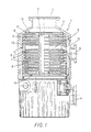
- Fig. 1 is a schematical cross-sectional view of a pump with an intermediate inlet, according to the invention;
- Fig. 2 is a perspective view of the stator stage located in correspondence with the intermediate inlet;
- Fig. 3 is a plan view of the stator stage shown in Fig. 2;
- Fig. 4 is a plan view showing the stator stage divided into two halves for allowing mounting on the rotor;
- Fig. 5 is a cross-sectional view according to a plane passing through line A-A in Fig. 2; and
- Fig. 6 is a cross-sectional view according to a plane passing through line B-B in Fig. 2.
- In Fig. 1, the turbomolecular pump in accordance with the invention, generally designated 1, has a
housing 2 into which open: a low-pressure inlet that, in the application of the pump to a leak detector, is connected to the test gas detector, not shown; a high-pressure outlet 4, communicating with the atmosphere or a fore pump; and an intermediate inlet 5 for the test gas, intended to flow in counter-current flow towards the detector. The pump has multiple stages, each associated with arotor impeller 6, carried by a shaft 7.Rotor impellers 6 cooperate with stator stages 8 arranged along the walls ofhousing 2. Intermediate inlet 5 opens into atransition chamber 9, separating a high-pressure pump section (the lower section), from a low-pressure pump section (the upper one). The two sections are designated 1A and 1B, respectively. Section 1B is the section operating in counter-current flow in the application to a leak detector. - No rotor impeller is provided in correspondence with transition chamber 9 (hence the pump has one pumping stage less than conventional pumps), and the chamber is limited upwards by a
stator stage 10 forming one of the novel features of the present invention. The remaining stator stages 8, as well asrotor impellers 6, are of conventional type. - Referring to Figs. 2 to 6,
stator stage 10 is a substantially cup-like member, comprising adisc 11 with acentral bore 16 where rotor shaft 7 passes, and aside wall 12, integral withdisc 11 and acting as a spacer ring. Such a structure allows a precise location ofstator stage 10 withinchamber 9. As shown in Fig. 4,stator stage 10 in effect comprises twoidentical portions 10', 10" that can be separated to allow mounting the stator about rotor shaft 7. The two portions are obtained by cuttingstator stage 10 along a diameter at the end of the manufacture. In Fig. 4, the elements in the two portions are designated by reference numerals with a prime or a double prime, respectively. -
Side wall 12 axially projects fromdisc 11 at both sides thereof and, as shown in Fig. 1, its total height substantially corresponds with the spacing between the last stator stage 8 of low pressure section 1B and the first stator stage 8 of high pressure section 1A. Portion 12A that, when the stator is mounted, is located on the side of high pressure pump section 1A, is higher than the other portion and has a high-conductance opening 13 formed therein, which communicates with intermediate inlet 5. Portion 12B located on the low pressure side has instead anannular groove 14 housing aresilient ring 15 arranged to keep the twohalves 10', 10" ofstator stage 10 in contact. - A plurality of
radial blades 17 is arranged along a peripheral portion ofdisc 11. Said blades are regularly spaced along the circumference ofdisc 11 and are separated bychannels 18 passing through the whole thickness ofdisc 11.Blades 17 are joined withdisc 11 not only at their radially inner edges, but also at their radially outer edges, where they end in correspondence ofspacer ring 12. Also thecorresponding separation channels 18 are thus closed at both ends. - As clearly shown in Fig. 6,
blades 17 form a very narrow angle with the plane ofdisc 11, andadjacent blades 17 overlap, leaving very narrow channels therebetween, so that the stage is made optically opaque in axial direction. In the embodiment shown, with eighteen blades, the angle is of about 10° and the separation channels have a constant thickness s of about 1 mm in radial direction. Those values allow attaining, atstator stage 10, a compression ratio of 2 for nitrogen and maintaining a molecular gas flow in the direction from inlet 3 tooutlet 4 up to pressures as high as about 100 mtorr (13,33 Pa) - that is the pump can tolerate a pressure of 13,33 Pa in the transition chamber - without losing the compression capacity of the upper stages. - It is evident that the above description is given only by way of non limiting example and that changes and modifications are possible without departing from the scope of the invention. In particular, the pump could include a plurality of stator stages made like
stage 10.
Claims (19)
- Turbine pump with a transition chamber (9) at an intermediate pressure separating a low-pressure section (1B) from a high-pressure section (1A), and with an additional inlet (5) opening into said chamber (9), characterised in that said chamber (9) is limited by a stator stage (10) integrated with a spacer ring and comprising a disc (11) having a peripheral edge (12), integral with said disc (11) and forming said spacer ring, and radial blades (17) located at the periphery of disc (11) and joined therewith at both a radially inner edge and a radially outer edge.
- A pump according to claim 1, characterised in that said blades are arranged at an acute angle relative to the surface of disc (11) such that adjacent blades (17) overlap with the interposition of separation channels (18) that pass through the whole thickness of disc (11), so as to make the stage optically opaque in axial direction.
- A pump according to claim 2, characterised in that said acute angle is of the order of 10°.
- A pump according to claim 2 or 3, characterised in that said separation channels (18) have a radially constant and defined thickness (s).
- A pump according to claim 4, characterised in that said thickness (s) is in the range 0.5 to 2 mm, and preferably of the order of 1 mm.
- A pump according to any preceding claim, characterised in that said peripheral edge (12) axially projects from said disc (11) in opposite directions and to different extents in both directions, and has, in a portion (12A) projecting to a greater extent, a high-conductance opening (13) communicating with said intermediate inlet (5).
- A pump according to claim 6, characterised in that said portion (12A) projecting to a greater extent is the portion located on the side of the high pressure section (1A).
- A pump according to any preceding claim, characterised in that said stator stage (10) has a central bore (16) where a rotor shaft (7) passes, and it is divided into two identical portions (10', 10") along a diametrical line, to allow mounting the stage (10) about said shaft (7).
- A pump according to any preceding claim, characterised in that it comprises at least a further stator stage integrated with a spacer ring.
- A pump according to claim 9, characterised in that said spacer ring (12) has, in a portion (12B) projecting to a lesser extent, an annular groove (14) housing a resilient ring (15) arranged to keep the two halves (10', 10") of stator stage (10) in contact.
- Turbine pump with a transition chamber (9) at an intermediate pressure separating a low-pressure section (1B) from a high-pressure section (1A) and with an additional inlet (5) opening into said chamber (9), said sections comprising multiple rotor stages (6) carried by a shaft (7) and multiple stator stages (8, 10) comprising each a bladed disc (11) surrounding the rotor shaft (7), said transition chamber (9) being defined on one side by a stator stage (10), characterised in that at least the stator stage (10) defining said transition chamber (9) has radial blades (17) that are arranged at an acute angle relative to the surface of the disc (11) such that adjacent blades (17) overlap so as to make the stage optically opaque in axial direction, and are separated by separation channels (18) that pass through the whole thickness of the disc (11).
- A pump according to claim 1, characterised in that said acute angle is of the order of 10°.
- A pump according to claim 1 or 2, characterised in that said separation channels (18) have a radially constant and defined thickness (s).
- A pump according to claim 3, characterised in that said thickness (s) is in the range 0.5 to 2 mm, and preferably is of the order of 1 mm.
- A pump according to any of claims 1 to 4, characterised in that the stator stage (10) defining said transition chamber (9) is located on the low-pressure side of the chamber (9).
- A pump according to claim 5, characterised in that the blades (17) of said stator stage (10) are joined at a radially outer edge with a peripheral edge (12) of the disc (11), which edge is integral with the disc (11) itself and forms a spacer ring; and are joined at a radially inner edge with a central annulus of the disc (11).
- A pump according to claim 6, characterised in that said peripheral edge (12) axially projects from said disc (11) in opposite directions and to different extents in both directions, and has, in a portion (12A) projecting to a greater extent, a high-conductance opening (13) communicating with said additional inlet (5).
- A pump according to claims 6 or 7, characterised in that it comprises at least a further stator stage integrated with a spacer ring.
- A pump according to any preceding claim, characterised in that said stator stage(s) (10) integrated with a spacer ring (12) is divided into two identical portions (10', 10") along a diametrical line, to allow mounting the stage (10) about the rotor shaft (7), and said spacer ring (12) has, in a portion (12B) projecting to a lesser extent, an annular groove (14) housing a resilient ring (15) arranged to keep the two halves (10', 10") of stator stage (10) in contact.
Priority Applications (4)
| Application Number | Priority Date | Filing Date | Title |
|---|---|---|---|
| EP01830178A EP1249613B1 (en) | 2001-03-15 | 2001-03-15 | Turbine pump with a stator stage integrated with a spacer ring |
| DE2001601898 DE60101898T2 (en) | 2001-03-15 | 2001-03-15 | Turbine pump with a stator stage integrated with a spacer ring |
| US10/159,911 US6676368B2 (en) | 2001-03-15 | 2002-05-31 | Turbine pump with a stator stage integrated with a spacer ring |
| JP2002171717A JP4050937B2 (en) | 2001-03-15 | 2002-06-12 | Turbine pump having a stator stage integrated with a spacer ring |
Applications Claiming Priority (2)
| Application Number | Priority Date | Filing Date | Title |
|---|---|---|---|
| EP01830178A EP1249613B1 (en) | 2001-03-15 | 2001-03-15 | Turbine pump with a stator stage integrated with a spacer ring |
| US10/159,911 US6676368B2 (en) | 2001-03-15 | 2002-05-31 | Turbine pump with a stator stage integrated with a spacer ring |
Publications (2)
| Publication Number | Publication Date |
|---|---|
| EP1249613A1 true EP1249613A1 (en) | 2002-10-16 |
| EP1249613B1 EP1249613B1 (en) | 2004-01-28 |
Family
ID=32095016
Family Applications (1)
| Application Number | Title | Priority Date | Filing Date |
|---|---|---|---|
| EP01830178A Revoked EP1249613B1 (en) | 2001-03-15 | 2001-03-15 | Turbine pump with a stator stage integrated with a spacer ring |
Country Status (3)
| Country | Link |
|---|---|
| US (1) | US6676368B2 (en) |
| EP (1) | EP1249613B1 (en) |
| JP (1) | JP4050937B2 (en) |
Cited By (4)
| Publication number | Priority date | Publication date | Assignee | Title |
|---|---|---|---|---|
| EP1443214A1 (en) * | 2003-02-03 | 2004-08-04 | Alcatel | Turbomolecular pump stator |
| WO2010105908A1 (en) * | 2009-03-19 | 2010-09-23 | Oerlikon Leybold Vacuum Gmbh | Multi-inlet vacuum pump |
| GB2557679A (en) * | 2016-12-15 | 2018-06-27 | Edwards Ltd | Stator blade unit for a turbomolecular pump |
| GB2601515A (en) * | 2020-12-02 | 2022-06-08 | Agilent Technologies Inc | Vacuum pump with elastic spacer |
Families Citing this family (11)
| Publication number | Priority date | Publication date | Assignee | Title |
|---|---|---|---|---|
| DE102004012713A1 (en) * | 2004-03-16 | 2005-10-06 | Pfeiffer Vacuum Gmbh | Turbo molecular pump |
| JP4676731B2 (en) * | 2004-09-10 | 2011-04-27 | エドワーズ株式会社 | Turbo molecular pump fixed blade and vacuum pump |
| JP4749054B2 (en) * | 2005-06-22 | 2011-08-17 | エドワーズ株式会社 | Turbomolecular pump and method of assembling turbomolecular pump |
| GB0618745D0 (en) * | 2006-09-22 | 2006-11-01 | Boc Group Plc | Molecular drag pumping mechanism |
| US7901177B2 (en) * | 2007-03-01 | 2011-03-08 | Siemens Energy, Inc. | Fluid pump having multiple outlets for exhausting fluids having different fluid flow characteristics |
| WO2009028099A1 (en) * | 2007-08-31 | 2009-03-05 | Shimadzu Corporation | Turbo molecular drag pump |
| JP5397138B2 (en) * | 2009-10-02 | 2014-01-22 | 株式会社島津製作所 | Turbo molecular pump |
| FR2966343B1 (en) | 2010-10-22 | 2012-12-07 | Tornier Sa | SET OF GLENOIDIAN COMPONENTS OF SHOULDER PROSTHESIS |
| TWI424121B (en) * | 2010-12-10 | 2014-01-21 | Prosol Corp | Turbo molecular pump with improved blade structures |
| GB2563406A (en) * | 2017-06-13 | 2018-12-19 | Edwards Ltd | Vacuum seal |
| EP4227538B1 (en) * | 2023-05-30 | 2025-03-26 | Pfeiffer Vacuum Technology AG | Vacuum pump with an inlet opening extending axially over a pump element |
Citations (6)
| Publication number | Priority date | Publication date | Assignee | Title |
|---|---|---|---|---|
| US4472962A (en) * | 1981-08-03 | 1984-09-25 | Balzers Aktiengesellschaft | Low pressure leak detector |
| US4550593A (en) * | 1981-08-26 | 1985-11-05 | Leybold-Heraeus Gmbh | Turbomolecular pump suitable for performing counterflow leakage tests |
| DE3922782A1 (en) * | 1988-07-12 | 1990-02-08 | Beijing Lab Of Vacuum Physics | Molecular pump in a unit design |
| US5585548A (en) * | 1992-08-26 | 1996-12-17 | Leybold Aktiengesellschaft | Counterflow leak-detector unit with a high-vacuum pump |
| US6030189A (en) * | 1995-10-20 | 2000-02-29 | Leybold Vakuum Gmbh | Friction vacuum pump with intermediate inlet |
| DE19937393A1 (en) * | 1999-08-07 | 2001-02-08 | Leybold Vakuum Gmbh | Stator ring for a turbomolecular vacuum pump |
Family Cites Families (4)
| Publication number | Priority date | Publication date | Assignee | Title |
|---|---|---|---|---|
| DE2035063C3 (en) * | 1970-07-15 | 1974-05-30 | Arthur Pfeiffer-Vakuumtechnik Gmbh, 6330 Wetzlar | Impeller for a turbo molecular pump |
| JPS6062692A (en) * | 1983-09-16 | 1985-04-10 | Hitachi Ltd | Stator blade of turbo molecular pump |
| IT1241177B (en) * | 1990-02-16 | 1993-12-29 | Varian Spa | STATOR FOR TURBOMOLECULAR PUMP. |
| US5733104A (en) * | 1992-12-24 | 1998-03-31 | Balzers-Pfeiffer Gmbh | Vacuum pump system |
-
2001
- 2001-03-15 EP EP01830178A patent/EP1249613B1/en not_active Revoked
-
2002
- 2002-05-31 US US10/159,911 patent/US6676368B2/en not_active Expired - Fee Related
- 2002-06-12 JP JP2002171717A patent/JP4050937B2/en not_active Expired - Fee Related
Patent Citations (6)
| Publication number | Priority date | Publication date | Assignee | Title |
|---|---|---|---|---|
| US4472962A (en) * | 1981-08-03 | 1984-09-25 | Balzers Aktiengesellschaft | Low pressure leak detector |
| US4550593A (en) * | 1981-08-26 | 1985-11-05 | Leybold-Heraeus Gmbh | Turbomolecular pump suitable for performing counterflow leakage tests |
| DE3922782A1 (en) * | 1988-07-12 | 1990-02-08 | Beijing Lab Of Vacuum Physics | Molecular pump in a unit design |
| US5585548A (en) * | 1992-08-26 | 1996-12-17 | Leybold Aktiengesellschaft | Counterflow leak-detector unit with a high-vacuum pump |
| US6030189A (en) * | 1995-10-20 | 2000-02-29 | Leybold Vakuum Gmbh | Friction vacuum pump with intermediate inlet |
| DE19937393A1 (en) * | 1999-08-07 | 2001-02-08 | Leybold Vakuum Gmbh | Stator ring for a turbomolecular vacuum pump |
Cited By (9)
| Publication number | Priority date | Publication date | Assignee | Title |
|---|---|---|---|---|
| EP1443214A1 (en) * | 2003-02-03 | 2004-08-04 | Alcatel | Turbomolecular pump stator |
| FR2850714A1 (en) * | 2003-02-03 | 2004-08-06 | Cit Alcatel | STATOR MULTI-STAGE TURBOMOLECULAR PUMP |
| US7588417B2 (en) | 2003-02-03 | 2009-09-15 | Alcatel | Turbomolecular pump having multistage stator spacers |
| WO2010105908A1 (en) * | 2009-03-19 | 2010-09-23 | Oerlikon Leybold Vacuum Gmbh | Multi-inlet vacuum pump |
| US8992162B2 (en) | 2009-03-19 | 2015-03-31 | Oerlikon Leybold Vacuum Gmbh | Multi-inlet vacuum pump |
| GB2557679A (en) * | 2016-12-15 | 2018-06-27 | Edwards Ltd | Stator blade unit for a turbomolecular pump |
| GB2601515A (en) * | 2020-12-02 | 2022-06-08 | Agilent Technologies Inc | Vacuum pump with elastic spacer |
| GB2601515B (en) * | 2020-12-02 | 2022-12-28 | Agilent Technologies Inc | Vacuum pump with elastic spacer |
| US11781553B2 (en) | 2020-12-02 | 2023-10-10 | Agilent Technologies, Inc. | Vacuum pump with elastic spacer |
Also Published As
| Publication number | Publication date |
|---|---|
| JP2004036389A (en) | 2004-02-05 |
| JP4050937B2 (en) | 2008-02-20 |
| EP1249613B1 (en) | 2004-01-28 |
| US6676368B2 (en) | 2004-01-13 |
| US20030223859A1 (en) | 2003-12-04 |
Similar Documents
| Publication | Publication Date | Title |
|---|---|---|
| EP1249613B1 (en) | Turbine pump with a stator stage integrated with a spacer ring | |
| JP3939352B2 (en) | Friction vacuum pump with intermediate intake | |
| US5238362A (en) | Turbomolecular pump | |
| US6705844B2 (en) | Dynamic seal | |
| EP2064449B1 (en) | Molecular drag pumping mechanism | |
| US5893702A (en) | Gas friction pump | |
| US3213794A (en) | Centrifugal pump with gas separation means | |
| US6709228B2 (en) | Vacuum pumps | |
| US4668160A (en) | Vacuum pump | |
| JP4348365B2 (en) | Leak detector with inflow section | |
| US7011491B2 (en) | Friction vacuum pump | |
| JP4520636B2 (en) | Friction vacuum pump with chassis, rotor and casing, and apparatus with this type of friction vacuum pump | |
| US20100176294A1 (en) | Mass spectrometer arrangement | |
| EP0445855A1 (en) | Improved turbomolecular pump | |
| EP0643227A1 (en) | Vacuum pumps | |
| JP5069264B2 (en) | Friction vacuum pump with chassis, rotor and casing and apparatus with this type of friction vacuum pump | |
| KR20010053279A (en) | Turbo-molecular pump | |
| US5456575A (en) | Non-centric improved pumping stage for turbomolecular pumps | |
| US10746189B2 (en) | Center bushing to balance axial forces in multi-stage pumps | |
| US7223064B2 (en) | Baffle configurations for molecular drag vacuum pumps | |
| US6644912B2 (en) | Gas friction pump | |
| US20080056886A1 (en) | Vacuum pumps with improved pumping channel cross sections | |
| JPS6336096A (en) | Vortex type vacuum pump | |
| GB2333127A (en) | Molecular drag compressors having finned rotor construction | |
| KR200178119Y1 (en) | Impeller |
Legal Events
| Date | Code | Title | Description |
|---|---|---|---|
| PUAI | Public reference made under article 153(3) epc to a published international application that has entered the european phase |
Free format text: ORIGINAL CODE: 0009012 |
|
| 17P | Request for examination filed |
Effective date: 20020423 |
|
| AK | Designated contracting states |
Kind code of ref document: A1 Designated state(s): AT BE CH CY DE DK ES FI FR GB GR IE IT LI LU MC NL PT SE TR |
|
| AX | Request for extension of the european patent |
Free format text: AL;LT;LV;MK;RO;SI |
|
| GRAH | Despatch of communication of intention to grant a patent |
Free format text: ORIGINAL CODE: EPIDOS IGRA |
|
| GRAH | Despatch of communication of intention to grant a patent |
Free format text: ORIGINAL CODE: EPIDOS IGRA |
|
| AKX | Designation fees paid |
Designated state(s): DE FR GB IT |
|
| GRAA | (expected) grant |
Free format text: ORIGINAL CODE: 0009210 |
|
| AK | Designated contracting states |
Kind code of ref document: B1 Designated state(s): DE FR GB IT |
|
| REG | Reference to a national code |
Ref country code: GB Ref legal event code: FG4D |
|
| REG | Reference to a national code |
Ref country code: IE Ref legal event code: FG4D |
|
| REF | Corresponds to: |
Ref document number: 60101898 Country of ref document: DE Date of ref document: 20040304 Kind code of ref document: P |
|
| ET | Fr: translation filed | ||
| PLBI | Opposition filed |
Free format text: ORIGINAL CODE: 0009260 |
|
| PLAX | Notice of opposition and request to file observation + time limit sent |
Free format text: ORIGINAL CODE: EPIDOSNOBS2 |
|
| 26 | Opposition filed |
Opponent name: PFEIFFER VACUUM GMBH Effective date: 20041026 |
|
| REG | Reference to a national code |
Ref country code: IE Ref legal event code: MM4A |
|
| PLAX | Notice of opposition and request to file observation + time limit sent |
Free format text: ORIGINAL CODE: EPIDOSNOBS2 |
|
| PLBB | Reply of patent proprietor to notice(s) of opposition received |
Free format text: ORIGINAL CODE: EPIDOSNOBS3 |
|
| PLCK | Communication despatched that opposition was rejected |
Free format text: ORIGINAL CODE: EPIDOSNREJ1 |
|
| APBP | Date of receipt of notice of appeal recorded |
Free format text: ORIGINAL CODE: EPIDOSNNOA2O |
|
| APAH | Appeal reference modified |
Free format text: ORIGINAL CODE: EPIDOSCREFNO |
|
| PLAB | Opposition data, opponent's data or that of the opponent's representative modified |
Free format text: ORIGINAL CODE: 0009299OPPO |
|
| R26 | Opposition filed (corrected) |
Opponent name: PFEIFFER VACUUM GMBH Effective date: 20041026 |
|
| APBQ | Date of receipt of statement of grounds of appeal recorded |
Free format text: ORIGINAL CODE: EPIDOSNNOA3O |
|
| APBU | Appeal procedure closed |
Free format text: ORIGINAL CODE: EPIDOSNNOA9O |
|
| PLAG | Information modified related to despatch of communication that opposition is rejected |
Free format text: ORIGINAL CODE: EPIDOSCREJ1 |
|
| PGFP | Annual fee paid to national office [announced via postgrant information from national office to epo] |
Ref country code: IT Payment date: 20100326 Year of fee payment: 10 |
|
| APBM | Appeal reference recorded |
Free format text: ORIGINAL CODE: EPIDOSNREFNO |
|
| APBP | Date of receipt of notice of appeal recorded |
Free format text: ORIGINAL CODE: EPIDOSNNOA2O |
|
| APAH | Appeal reference modified |
Free format text: ORIGINAL CODE: EPIDOSCREFNO |
|
| APBQ | Date of receipt of statement of grounds of appeal recorded |
Free format text: ORIGINAL CODE: EPIDOSNNOA3O |
|
| PGFP | Annual fee paid to national office [announced via postgrant information from national office to epo] |
Ref country code: FR Payment date: 20110317 Year of fee payment: 11 |
|
| REG | Reference to a national code |
Ref country code: GB Ref legal event code: 732E Free format text: REGISTERED BETWEEN 20110505 AND 20110511 |
|
| PGFP | Annual fee paid to national office [announced via postgrant information from national office to epo] |
Ref country code: GB Payment date: 20110309 Year of fee payment: 11 |
|
| REG | Reference to a national code |
Ref country code: DE Ref legal event code: R081 Ref document number: 60101898 Country of ref document: DE Owner name: AGILENT TECHNOLOGIES, INC., US Free format text: FORMER OWNER: VARIAN S.P.A., LEINI, IT Effective date: 20110809 Ref country code: DE Ref legal event code: R082 Ref document number: 60101898 Country of ref document: DE Representative=s name: DILG HAEUSLER SCHINDELMANN PATENTANWALTSGESELL, DE Effective date: 20110809 Ref country code: DE Ref legal event code: R081 Ref document number: 60101898 Country of ref document: DE Owner name: AGILENT TECHNOLOGIES ITALIA S.P.A., IT Free format text: FORMER OWNER: VARIAN S.P.A., LEINI, IT Effective date: 20110809 Ref country code: DE Ref legal event code: R081 Ref document number: 60101898 Country of ref document: DE Owner name: AGILENT TECHNOLOGIES, INC., SANTA CLARA, US Free format text: FORMER OWNER: VARIAN S.P.A., LEINI, TURIN/TORINO, IT Effective date: 20110809 |
|
| REG | Reference to a national code |
Ref country code: FR Ref legal event code: TP Owner name: AGILENT TECHNOLOGIES ITALIA, S.P.A., IT Effective date: 20110922 |
|
| PG25 | Lapsed in a contracting state [announced via postgrant information from national office to epo] |
Ref country code: IT Free format text: LAPSE BECAUSE OF NON-PAYMENT OF DUE FEES Effective date: 20110315 |
|
| RAP2 | Party data changed (patent owner data changed or rights of a patent transferred) |
Owner name: AGILENT TECHNOLOGIES ITALIA S.P.A. |
|
| RAP2 | Party data changed (patent owner data changed or rights of a patent transferred) |
Owner name: AGILENT TECHNOLOGIES, INC. |
|
| GBPC | Gb: european patent ceased through non-payment of renewal fee |
Effective date: 20120315 |
|
| REG | Reference to a national code |
Ref country code: FR Ref legal event code: ST Effective date: 20121130 |
|
| PG25 | Lapsed in a contracting state [announced via postgrant information from national office to epo] |
Ref country code: GB Free format text: LAPSE BECAUSE OF NON-PAYMENT OF DUE FEES Effective date: 20120315 Ref country code: FR Free format text: LAPSE BECAUSE OF NON-PAYMENT OF DUE FEES Effective date: 20120402 |
|
| REG | Reference to a national code |
Ref country code: DE Ref legal event code: R082 Ref document number: 60101898 Country of ref document: DE Representative=s name: DILG HAEUSLER SCHINDELMANN PATENTANWALTSGESELL, DE |
|
| REG | Reference to a national code |
Ref country code: DE Ref legal event code: R103 Ref document number: 60101898 Country of ref document: DE Ref country code: DE Ref legal event code: R064 Ref document number: 60101898 Country of ref document: DE |
|
| APBU | Appeal procedure closed |
Free format text: ORIGINAL CODE: EPIDOSNNOA9O |
|
| PGFP | Annual fee paid to national office [announced via postgrant information from national office to epo] |
Ref country code: DE Payment date: 20130314 Year of fee payment: 13 |
|
| REG | Reference to a national code |
Ref country code: DE Ref legal event code: R082 Ref document number: 60101898 Country of ref document: DE Representative=s name: DILG HAEUSLER SCHINDELMANN PATENTANWALTSGESELL, DE |
|
| REG | Reference to a national code |
Ref country code: DE Ref legal event code: R082 Ref document number: 60101898 Country of ref document: DE Representative=s name: DILG HAEUSLER SCHINDELMANN PATENTANWALTSGESELL, DE Effective date: 20130521 Ref country code: DE Ref legal event code: R081 Ref document number: 60101898 Country of ref document: DE Owner name: AGILENT TECHNOLOGIES, INC., US Free format text: FORMER OWNER: AGILENT TECHNOLOGIES ITALIA S.P.A., CERNUSCO SUL NAVIGLIO, IT Effective date: 20130521 Ref country code: DE Ref legal event code: R081 Ref document number: 60101898 Country of ref document: DE Owner name: AGILENT TECHNOLOGIES, INC., SANTA CLARA, US Free format text: FORMER OWNER: AGILENT TECHNOLOGIES ITALIA S.P.A., CERNUSCO SUL NAVIGLIO, MILANO, IT Effective date: 20130521 Ref country code: DE Ref legal event code: R082 Ref document number: 60101898 Country of ref document: DE Representative=s name: DILG HAEUSLER SCHINDELMANN PATENTANWALTSGESELL, DE Effective date: 20130206 |
|
| RDAF | Communication despatched that patent is revoked |
Free format text: ORIGINAL CODE: EPIDOSNREV1 |
|
| RDAG | Patent revoked |
Free format text: ORIGINAL CODE: 0009271 |
|
| STAA | Information on the status of an ep patent application or granted ep patent |
Free format text: STATUS: PATENT REVOKED |
|
| 27W | Patent revoked |
Effective date: 20130219 |
|
| REG | Reference to a national code |
Ref country code: DE Ref legal event code: R107 Ref document number: 60101898 Country of ref document: DE Effective date: 20131107 |