EP1249370A1 - Wire-guiding plaque for the electrical equipment of a motor vehicle - Google Patents
Wire-guiding plaque for the electrical equipment of a motor vehicle Download PDFInfo
- Publication number
- EP1249370A1 EP1249370A1 EP20020006232 EP02006232A EP1249370A1 EP 1249370 A1 EP1249370 A1 EP 1249370A1 EP 20020006232 EP20020006232 EP 20020006232 EP 02006232 A EP02006232 A EP 02006232A EP 1249370 A1 EP1249370 A1 EP 1249370A1
- Authority
- EP
- European Patent Office
- Prior art keywords
- plaque
- guiding
- wire
- plate
- wires
- Prior art date
- Legal status (The legal status is an assumption and is not a legal conclusion. Google has not performed a legal analysis and makes no representation as to the accuracy of the status listed.)
- Granted
Links
- 230000037431 insertion Effects 0.000 description 2
- 238000003780 insertion Methods 0.000 description 2
- 230000002093 peripheral effect Effects 0.000 description 1
Images

Classifications
-
- B—PERFORMING OPERATIONS; TRANSPORTING
- B60—VEHICLES IN GENERAL
- B60R—VEHICLES, VEHICLE FITTINGS, OR VEHICLE PARTS, NOT OTHERWISE PROVIDED FOR
- B60R16/00—Electric or fluid circuits specially adapted for vehicles and not otherwise provided for; Arrangement of elements of electric or fluid circuits specially adapted for vehicles and not otherwise provided for
- B60R16/02—Electric or fluid circuits specially adapted for vehicles and not otherwise provided for; Arrangement of elements of electric or fluid circuits specially adapted for vehicles and not otherwise provided for electric constitutive elements
- B60R16/0207—Wire harnesses
- B60R16/0215—Protecting, fastening and routing means therefor
Definitions
- the present invention relates to a wire-guiding plaque for the electrical equipment of a motor vehicle. More in particular, the term "wire-guiding plaque" indicates a peculiar kind of plug adapted to close a hole on the upright of the door, used to make the wires and the connector of the electrical equipment pass from the front of the bodywork to the door.
- the plaque is used only to make the bundle of wires pass through a slit made on it.
- the end of the bundle of wires provided with the connector is then either let hanging free inside the door, in economical versions, or connected to a support which fixed or made on the door inside the finishing panel, in more expensive versions.
- reference number 1 indicates the plastic "wire-guiding plaque" for a motor-vehicle.
- wire-guiding plaque indicates a peculiar kind of plug adapted to close a hole on the upright of the door, used to make the wires and the connector of the electrical equipment pass from the front of the bodywork to the door.
- the plaque therefore presents a plug element 2 of cylindrical shape the thickness of which is reduced but enough to be snap inserted, by means of a peripheral tooth 3, into a hole made on the upright of the door.
- a rectangular cavity 4 which is actually basically square and closed at its bottom by two basically rectangular wings 6 and 7, each one of these wings occupying half of the cavity 4 and being connected by one side, through a film hinge, to the body of the plaque 1, at the side of the cavity 4.
- the plate 14 is provided with engagements 16 to snap connect the connector 18 of the bundle of wires 10 as well as with a semicircular recess 19 at the centre of the edge facing the hole 9 when the plate is snap inserted into the cavity 4. Its dimension is such that it slightly reduces the diameter of the hole 9 so that the bundle of wires 10 is pinched when inserted. The correct direction and side of insertion of the plate are given since the plate is connected to the plaque by the strap 15 so that it cannot be rotated.
- wire-guiding plaque is used is shown in figures 4 to 6 where part of the front bodywork 21 and part of the upright 22 of the front door are visible.
Landscapes
- Engineering & Computer Science (AREA)
- Mechanical Engineering (AREA)
- Installation Of Indoor Wiring (AREA)
- Current-Collector Devices For Electrically Propelled Vehicles (AREA)
- Platform Screen Doors And Railroad Systems (AREA)
- Electrical Discharge Machining, Electrochemical Machining, And Combined Machining (AREA)
- Electric Cable Arrangement Between Relatively Moving Parts (AREA)
- Details Of Connecting Devices For Male And Female Coupling (AREA)
Abstract
Description
- The present invention relates to a wire-guiding plaque for the electrical equipment of a motor vehicle. More in particular, the term "wire-guiding plaque" indicates a peculiar kind of plug adapted to close a hole on the upright of the door, used to make the wires and the connector of the electrical equipment pass from the front of the bodywork to the door.
- Presently the plaque is used only to make the bundle of wires pass through a slit made on it. The end of the bundle of wires provided with the connector is then either let hanging free inside the door, in economical versions, or connected to a support which fixed or made on the door inside the finishing panel, in more expensive versions.
- Both solutions present the following drawbacks: in the first solution disturbing noises can be generated inside the passenger compartment due to the friction of the bundle of wires, or of the connection system, against the frame of the door or the finishing panel; in the second solution the additional components and the long assembly time cause higher costs.
- It is an object of the present invention to overcome the inconveniences described above by means of a plaque that closes the through hole for the bundle of wires and at the same time fixes it also providing a point of engagement for the connector.
- Said object is achieved according to the invention by means of a plastic wire-guiding plaque, adapted to close the hole that lets the electrical wires of a motor vehicle pass from the front bodywork to the upright of the door, presenting the characteristics set forth in
claim 1. - Additional characteristics and advantages will become more clear from the following description referring to the appended drawings provided as non-restrictive example and in which:
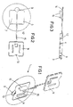
- figure 1 is a perspective view of the plaque according to the invention, the open position of the plaque to engage the connector and fix bundle of wires being indicated by a broken line and the closed position of the plaque being indicated by a continuous line;
- figure 2 is a rear plant view of the plaque in figure 1 with the plaque to engage the connector being in its open position;
- figure 3 is a side section view of the plaque in figure 2;
- figures 4 to 6 show the way the plaque is used, that is a first stage in which the bundle of wires of the electrical equipment is not inserted; a second stage in which the bundle of wires is inserted and the plaque to engage the connector is in its open position; a third stage in which the plaque to engage the connector is in its closed position, the bundle of wires is fixed and the connector is locked on the plaque.
-
- With reference to the figures,
reference number 1 indicates the plastic "wire-guiding plaque" for a motor-vehicle. In the case shown, the term wire-guiding plaque indicates a peculiar kind of plug adapted to close a hole on the upright of the door, used to make the wires and the connector of the electrical equipment pass from the front of the bodywork to the door. - The plaque therefore presents a plug element 2 of cylindrical shape the thickness of which is reduced but enough to be snap inserted, by means of a
peripheral tooth 3, into a hole made on the upright of the door. In the middle of the plaque there is arectangular cavity 4, which is actually basically square and closed at its bottom by two basicallyrectangular wings 6 and 7, each one of these wings occupying half of thecavity 4 and being connected by one side, through a film hinge, to the body of theplaque 1, at the side of thecavity 4. On one of the sides of thecavity 4, at one end of the slit defined by the two facing wings, there is a basicallycylindrical hole 9 which is perpendicular to the plug element 2 the diameter of which, being congruous to the dimension of the bundle ofwires 10 which is to be placed inside it (fig.4), lays on the plane which is tangent to said side. Two sides of the upper edge of thecavity 4 are provided with atooth 12 adapted to snap engage aplastic plate 14 connected to the plaque by means of astrap 15. - The
plate 14 is provided withengagements 16 to snap connect theconnector 18 of the bundle ofwires 10 as well as with asemicircular recess 19 at the centre of the edge facing thehole 9 when the plate is snap inserted into thecavity 4. Its dimension is such that it slightly reduces the diameter of thehole 9 so that the bundle ofwires 10 is pinched when inserted. The correct direction and side of insertion of the plate are given since the plate is connected to the plaque by thestrap 15 so that it cannot be rotated. - The way the wire-guiding plaque is used is shown in figures 4 to 6 where part of the
front bodywork 21 and part of the upright 22 of the front door are visible. - The bundle of
wires 10 provided with aprotection cap 23, protrudes from thebodywork 21 and is inserted into the door through theplaque 1 on the upright 22. The insertion of the bundle ofwires 10, provided with theconnector 18, is allowed by thewings 6 and 7 which move and rotate on their film hinges. Once the bundle ofwires 10 has passed (fig. 5) it can be fixed by means of snap closing of theplate 14 on theplaque 1. It is therefore possible to insert theconnector 18 into thesnap engagements 16 of theplate 14 and to connect to it another connector 24 (fig. 6) from the part of electrical equipment already installed on the door. - In this way it is possible to easily and quickly fix both the bundle of wires and the connector inside the door, as well as to close the hole on the upright of the door which the bundle of wires passes through.
Claims (5)
- Plastic wire-guiding plaque adapted to close a hole on the upright of the door, used to make the wires and the connector of the electrical equipment pass from the front of the bodywork to the door, the plaque being located on said upright and characterised in that it consists of:a plug element (2) of basically cylindrical shape which can be snap inserted into said hole and is provided with a rectangular cavity (4) closed at its bottom by mobile wings (6, 7);a plate (14) provided with engagements for one or more connectors of the electrical equipment of the motor vehicle, adapted to be snap inserted into said rectangular cavity (4), anda flexible connection element between said plug element (2) and said plate (14).
- Wire-guiding plaque as claimed in claim 1, characterised in that one of the sides of the rectangular cavity (4) is provided with a basically cylindrical hole (9) perpendicular to the element (2) and the diameter of which, being congruous to the dimension of the bundle of wires (10), lays on the plane which is tangent to said one side.
- Wire-guiding plaque as claimed in claim 1 and 2, characterised in that one of the sides of the plate (14) presents a semicircular recess (19) the radius of which is shorter than the radius of said cylindrical hole (9).
- Wire-guiding plaque as claimed in claim 1, characterised in that at least two of the sides of the cavity (4) present teeth (12) to snap engage the plate (14).
- Wire-guiding plaque as claimed in claim 1, characterised in that the flexible connection element is a strap integral both to the plug element (2) and to the plate (14).
Applications Claiming Priority (2)
| Application Number | Priority Date | Filing Date | Title |
|---|---|---|---|
| ITTO010351 | 2001-04-11 | ||
| IT2001TO000351A ITTO20010351A1 (en) | 2001-04-11 | 2001-04-11 | CABLE GUIDE OF THE ELECTRIC SYSTEM OF A VEHICLE. |
Publications (2)
| Publication Number | Publication Date |
|---|---|
| EP1249370A1 true EP1249370A1 (en) | 2002-10-16 |
| EP1249370B1 EP1249370B1 (en) | 2004-10-13 |
Family
ID=11458780
Family Applications (1)
| Application Number | Title | Priority Date | Filing Date |
|---|---|---|---|
| EP02006232A Expired - Lifetime EP1249370B1 (en) | 2001-04-11 | 2002-03-20 | Wire-guiding plaque for the electrical equipment of a motor vehicle |
Country Status (4)
| Country | Link |
|---|---|
| EP (1) | EP1249370B1 (en) |
| DE (1) | DE60201548T2 (en) |
| ES (1) | ES2230412T3 (en) |
| IT (1) | ITTO20010351A1 (en) |
Cited By (1)
| Publication number | Priority date | Publication date | Assignee | Title |
|---|---|---|---|---|
| FR2988447A1 (en) * | 2012-03-20 | 2013-09-27 | Peugeot Citroen Automobiles Sa | Connector support staple for electrical harness in vehicle i.e. car, has connector support element and sealing lip arranged on level of anchoring foot, and fixing unit of extension includes additional connector support element |
Citations (3)
| Publication number | Priority date | Publication date | Assignee | Title |
|---|---|---|---|---|
| US5588260A (en) * | 1994-05-30 | 1996-12-31 | Kansei Corporation | Construction of a vehicle door provided with a wiring harness and a waterproof grommet used in the construction |
| US5639993A (en) * | 1994-07-19 | 1997-06-17 | Sumitomo Wiring Systems Ltd. | Grommet |
| DE19959429A1 (en) * | 1998-12-09 | 2000-06-21 | Yazaki Corp | Passage grommet for panel of vehicle to hold cable harness which is cabled between passage grommet body and panel in watertight design, has body and inner passage element with elastic holder. |
-
2001
- 2001-04-11 IT IT2001TO000351A patent/ITTO20010351A1/en unknown
-
2002
- 2002-03-20 DE DE60201548T patent/DE60201548T2/en not_active Expired - Lifetime
- 2002-03-20 EP EP02006232A patent/EP1249370B1/en not_active Expired - Lifetime
- 2002-03-20 ES ES02006232T patent/ES2230412T3/en not_active Expired - Lifetime
Patent Citations (3)
| Publication number | Priority date | Publication date | Assignee | Title |
|---|---|---|---|---|
| US5588260A (en) * | 1994-05-30 | 1996-12-31 | Kansei Corporation | Construction of a vehicle door provided with a wiring harness and a waterproof grommet used in the construction |
| US5639993A (en) * | 1994-07-19 | 1997-06-17 | Sumitomo Wiring Systems Ltd. | Grommet |
| DE19959429A1 (en) * | 1998-12-09 | 2000-06-21 | Yazaki Corp | Passage grommet for panel of vehicle to hold cable harness which is cabled between passage grommet body and panel in watertight design, has body and inner passage element with elastic holder. |
Cited By (1)
| Publication number | Priority date | Publication date | Assignee | Title |
|---|---|---|---|---|
| FR2988447A1 (en) * | 2012-03-20 | 2013-09-27 | Peugeot Citroen Automobiles Sa | Connector support staple for electrical harness in vehicle i.e. car, has connector support element and sealing lip arranged on level of anchoring foot, and fixing unit of extension includes additional connector support element |
Also Published As
| Publication number | Publication date |
|---|---|
| ITTO20010351A0 (en) | 2001-04-11 |
| DE60201548T2 (en) | 2005-02-24 |
| DE60201548D1 (en) | 2004-11-18 |
| EP1249370B1 (en) | 2004-10-13 |
| ES2230412T3 (en) | 2005-05-01 |
| ITTO20010351A1 (en) | 2002-10-11 |
Similar Documents
| Publication | Publication Date | Title |
|---|---|---|
| JP3348765B2 (en) | Routing structure of door harness | |
| US6392147B1 (en) | Protector that snaps over routed parts | |
| JP2964445B2 (en) | Harness protector | |
| JP3287535B2 (en) | Connector mounting structure | |
| JP2011230593A (en) | Carpet clamp | |
| EP1363375A1 (en) | Wire harness protector | |
| EP2950409B1 (en) | Power supply device | |
| CN1969431B (en) | Plug connector | |
| US5806812A (en) | Adjustable attachment unit | |
| KR20190138281A (en) | Interior component of a vehicle | |
| US20110175000A1 (en) | Pressure relief valve | |
| JP2001132871A (en) | Grommet for wire harness | |
| KR20070121539A (en) | Forced fitting of sensor assembly in electronic throttle valve control | |
| EP1249370B1 (en) | Wire-guiding plaque for the electrical equipment of a motor vehicle | |
| JP2003153422A (en) | Harness slack absorbing device | |
| JP2001317532A (en) | Device for locking sheath of remote control device via cable | |
| JP3459039B2 (en) | Bending protector and harness accommodating method using the same | |
| JP3928299B2 (en) | Wire harness mounting structure | |
| JP5040837B2 (en) | Clamp | |
| JP3913987B2 (en) | Connection structure for flat cable connector | |
| JP3760798B2 (en) | Fuse box battery mounting structure | |
| JPH054718U (en) | Protector for wire harness | |
| EP1098402B1 (en) | Door with support panel for electrical components | |
| CN211308413U (en) | Vehicle event data recorder mounting structure and vehicle | |
| JP2003079036A (en) | Wire clamp |
Legal Events
| Date | Code | Title | Description |
|---|---|---|---|
| PUAI | Public reference made under article 153(3) epc to a published international application that has entered the european phase |
Free format text: ORIGINAL CODE: 0009012 |
|
| AK | Designated contracting states |
Kind code of ref document: A1 Designated state(s): AT BE CH CY DE DK ES FI FR GB GR IE IT LI LU MC NL PT SE TR |
|
| AX | Request for extension of the european patent |
Free format text: AL;LT;LV;MK;RO;SI |
|
| 17P | Request for examination filed |
Effective date: 20021009 |
|
| AKX | Designation fees paid |
Designated state(s): DE ES FR GB IT SE |
|
| GRAP | Despatch of communication of intention to grant a patent |
Free format text: ORIGINAL CODE: EPIDOSNIGR1 |
|
| RBV | Designated contracting states (corrected) |
Designated state(s): DE ES FR GB IT SE |
|
| GRAS | Grant fee paid |
Free format text: ORIGINAL CODE: EPIDOSNIGR3 |
|
| GRAA | (expected) grant |
Free format text: ORIGINAL CODE: 0009210 |
|
| AK | Designated contracting states |
Kind code of ref document: B1 Designated state(s): DE ES FR GB IT SE |
|
| PG25 | Lapsed in a contracting state [announced via postgrant information from national office to epo] |
Ref country code: IT Free format text: LAPSE BECAUSE OF FAILURE TO SUBMIT A TRANSLATION OF THE DESCRIPTION OR TO PAY THE FEE WITHIN THE PRESCRIBED TIME-LIMIT;WARNING: LAPSES OF ITALIAN PATENTS WITH EFFECTIVE DATE BEFORE 2007 MAY HAVE OCCURRED AT ANY TIME BEFORE 2007. THE CORRECT EFFECTIVE DATE MAY BE DIFFERENT FROM THE ONE RECORDED. Effective date: 20041013 |
|
| REG | Reference to a national code |
Ref country code: GB Ref legal event code: FG4D |
|
| REG | Reference to a national code |
Ref country code: IE Ref legal event code: FG4D |
|
| REF | Corresponds to: |
Ref document number: 60201548 Country of ref document: DE Date of ref document: 20041118 Kind code of ref document: P |
|
| REG | Reference to a national code |
Ref country code: SE Ref legal event code: TRGR |
|
| REG | Reference to a national code |
Ref country code: ES Ref legal event code: FG2A Ref document number: 2230412 Country of ref document: ES Kind code of ref document: T3 |
|
| PLBE | No opposition filed within time limit |
Free format text: ORIGINAL CODE: 0009261 |
|
| STAA | Information on the status of an ep patent application or granted ep patent |
Free format text: STATUS: NO OPPOSITION FILED WITHIN TIME LIMIT |
|
| ET | Fr: translation filed | ||
| 26N | No opposition filed |
Effective date: 20050714 |
|
| REG | Reference to a national code |
Ref country code: FR Ref legal event code: PLFP Year of fee payment: 15 |
|
| REG | Reference to a national code |
Ref country code: FR Ref legal event code: PLFP Year of fee payment: 16 |
|
| PGFP | Annual fee paid to national office [announced via postgrant information from national office to epo] |
Ref country code: DE Payment date: 20170314 Year of fee payment: 16 Ref country code: FR Payment date: 20170213 Year of fee payment: 16 Ref country code: SE Payment date: 20170313 Year of fee payment: 16 |
|
| PGFP | Annual fee paid to national office [announced via postgrant information from national office to epo] |
Ref country code: GB Payment date: 20170315 Year of fee payment: 16 |
|
| PGFP | Annual fee paid to national office [announced via postgrant information from national office to epo] |
Ref country code: ES Payment date: 20170214 Year of fee payment: 16 |
|
| REG | Reference to a national code |
Ref country code: DE Ref legal event code: R119 Ref document number: 60201548 Country of ref document: DE |
|
| PG25 | Lapsed in a contracting state [announced via postgrant information from national office to epo] |
Ref country code: SE Free format text: LAPSE BECAUSE OF NON-PAYMENT OF DUE FEES Effective date: 20180321 |
|
| GBPC | Gb: european patent ceased through non-payment of renewal fee |
Effective date: 20180320 |
|
| PG25 | Lapsed in a contracting state [announced via postgrant information from national office to epo] |
Ref country code: DE Free format text: LAPSE BECAUSE OF NON-PAYMENT OF DUE FEES Effective date: 20181002 |
|
| PG25 | Lapsed in a contracting state [announced via postgrant information from national office to epo] |
Ref country code: GB Free format text: LAPSE BECAUSE OF NON-PAYMENT OF DUE FEES Effective date: 20180320 |
|
| PG25 | Lapsed in a contracting state [announced via postgrant information from national office to epo] |
Ref country code: FR Free format text: LAPSE BECAUSE OF NON-PAYMENT OF DUE FEES Effective date: 20180331 |
|
| REG | Reference to a national code |
Ref country code: ES Ref legal event code: FD2A Effective date: 20190911 |
|
| PG25 | Lapsed in a contracting state [announced via postgrant information from national office to epo] |
Ref country code: ES Free format text: LAPSE BECAUSE OF NON-PAYMENT OF DUE FEES Effective date: 20180321 |