Field of Invention:
This invention relates to discrete multitone (DMT) modems,
such as asymmetric digital subscriber line (ADSL) modems, and
more particularly to a power conserving state known as Quiescent
mode (Q-mode).
Background of Invention:
ADSL modems employing DMT modulation are used for internet
access. The ADSL standard is described in S.Palm (ed),
"Asymmetrical Digital Subscriber Line (ADSL) Transceivers," ITU-T
Q4/SG15, G.992.1, 1999, incorporated herein by reference.
ADSL modems are well known. For example see U.S. Patent No.
6,055,268 of Timm et al. For DMT modems see U.S. Patent No.
5,400,322; 5,479,447;5,317,596 and 5,285,474. These patents are
incorporated herein by reference. Q-mode is a proposed power
conserving idle state that an ADSL modem can enter when it has
no data to transmit. To prevent the generation of pulsating
crosstalk, an ADSL modem should transmit an idle signal in the
power conserving state with an average power similar to that of
a data signal. Pulsating crosstalk occurs when the average
power of the signal on the line changes, affecting neighboring
lines in a bundle. Since most modems perform better with
stationary crosstalk, it is desirable to minimize changes to the
average power of the signal on the line. By reducing the peak-to-average
ratio (PAR) of the idle signal without changing the
average power, the ADSL analog front end (AFE) can achieve a
power savings without disrupting neighboring lines in a bundle.
Summary of Invention:
In accordance with one embodiment of the present invention
for the power saving Q-Mode, when there is no data to transmit
the PAR of the signal is reduced while the average power of the
signal remains the same. The low PAR Q-mode signal design takes
the effects of the AFE into account in finding a low PAR signal.
The Q-mode signal is tailored to the AFE and loaded subchannels
to realize maximum power savings.
Description of Drawings:
Figure 1 illustrates a DMT transmitter architecture
according to one embodiment of the present invention which
allows for alignment of an all zero bit stream with low PAR DMT
symbol;
Figure 2 illustrates a receiver for Q-mode according to one
embodiment;
Figure 3 illustrates a conceptual view of the exclusive-or
(XOR) mapping with no inner code;
Figure 4 illustrates a conceptual view of the XOR mapping
with 4D trellis coded modulation (TCM);
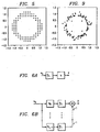
Figure 5 illustrates the points in a 8 bit constellation
within ± 1.5 dB of the average power of the constellation;
Figure 6a illustrates upsampling and filtering and Figure
6b to the equivalent polyphase representation;
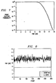
Figure 7 illustrates the frame clipping probability of a
normal or Showtime DMT signal for a given allowed PAR;
Figure 8 illustrates Showtime and Q-mode PAR for a 26 gauge
(AWG) 12 kft channel with allowed constellation points within ±
1.5 dB of the average power for the constellation; and
Figure 9 illustrates a mapping of a zero input.
Description of Preferred Embodiments of the Present Invention:
A provisional application serial no. 60/282,128 for the
subject invention was filed on April 6,2001 for the inventor
Arthur Redfern. This application is incorporated herein by
reference.
In a number of Q-mode proposals, the transmission
convergence (TPS-TC) layer converts Idle data into an all zero
bit stream which propagates down to the physical layer. If the
bits to DMT symbol mapping maps the all zero bit stream to a low
PAR DMT symbol, power savings can be achieved in the AFE.
Additionally, if the transmitter and receiver process Showtime
(normal data transmissions) and Idle data identically, then the
transmitter can achieve the power savings without requiring the
intervention of the receiver.
The following sections present an architecture for mapping
an all zero bit stream to a low PAR DMT symbol. Notable aspects
of the proposed architecture include:
- A minimal amount of changes and complexity increase over the
existing DMT transmitter (most notably the removal of a
scrambler and the addition of an XOR mapping and symbol
inverter).
- A power for each subchannel similar to that of the average
power for the constellation to minimize the generation of
pulsating crosstalk.
- A simple method for optimizing the mapping for a given bit
loading and AFE.
- Identical operation for Showtime and Idle data.
- Compatibility with TCM, turbo, and low density parity check
(LDPC) inner codes.
- Compatibility with all timing recovery methods.
Simulation results illustrate the ability of the proposed
architecture and optimization procedure to map an all zero bit
stream to a low PAR signal for a variety of channels.
Architecture:
The architecture section describes the physical layer DMT
transmitter architecture used to form the low PAR mapping, and
the constraints on the XOR mapping.
Figure 1 illustrates the proposed architecture for the DMT
transmitter. The DMT transmitter architecture allows for the
alignment of an all zero bit stream with a low PAR DMT symbol.
The inner code includes no code, TCM, turbo, and LDPC schemes.
Before the physical layer shown in Fig. 1 there is the data
input, framing and access control. Forward error connection
(FEC) 11, interleaving 13, and tone ordering 15 are applied to
the data bits. The XOR mapper 17 provides mapping to all of the
bits of the output of the tone ordering. The inner code 19 and
constellation encoders 21l-21n are applied to the output of the
XOR mapping 17. The Inverse Fast Fourier Transform (IFFT) 23
and symbol inversion 25 are applied to the encoded constellation
points. Although not shown in Fig. 1, after the symbol
inversion there is digital to analog conversion and
amplification before coupling to a channel such as a twisted
pair wire.
The XOR mapping 17 is chosen such that it maps an all zero
bit stream into a low PAR DMT symbol (its design will be
considered in PAR Minimization section). The symbol inverter
25, controlled by a pseudo random binary sequence (PRBS), is
used to prevent the generation of a transmitted sequence with a
period equal to that of the DMT symbol period. The XOR mapping
17 and symbol inverter 25 are applied to all data.
The receiver is illustrated in Fig. 2. In the receiver
operations take place in the reverse order with the received
signal undergoing analog to digital conversion, symbol inversion
27, Fast Fourier Transform (FFT) processing 28, constellation
decoding 29 to bits, innercode decoding 30, XOR inverse mapper
31 providing inverse mapping, tone deordering 32 and FEC 33
decoding. Notice that the XOR mapping 17 occurs before the
inner code 19 at the transmitter, and after the inner code 30 at
the receiver. This allows existing constellation mappers, TCM
encoders/decoders, and other advanced inner codes to be used
without modification.
Figure 1 shows the XOR mapping 17 being applied to the
whole tone ordered bit sequence. However, in the design of the
mapping it is often more convenient to think of its effects on
each subchannel. Figures 3 and 4 show how the mapping can be
conceptually viewed as operating on subchannels individually
(for the case of no inner code), or operating on a pair of
subchannels at a time (for the case of 4D TCM). Figure 3
illustrates conceptual view of the XOR mapping with no inner
code. The XOR mapping can be thought of as divided into N parts
(17l - 17n), with each part associated with a subchannel. Figure
4 illustrates conceptual view of the XOR mapping 17l - 17n with
4D TCM (Trellis-coded modulation) with Trellis encoders 22l-22n.
The XOR mapping can be thought of as divided into N/2 parts 22l-22n,
with each part associated with 2 subchannels.
Mapping Constraints:
A constraint on the XOR mapping is that for each subchannel
it maps a zero input to a constellation point whose power is
within some range of the average power of the constellation for
that subchannel. As an example, Figure 5 plots all of the
points within ±1.5 dB of the average power for an 8 bit
constellation. In general, this type of power constraint forms
a ring. Table 1 lists the number of points within ±1.5 dB of
the average power for 2, ..., 15 bits. The more points in the
constellation, the more degrees of freedom there will be in the
design of the mappings.
In the choice of the XOR mappings, the mapping design
procedure needs to be aware of the effect of the inner code on
the mapping. The inner code will modify some or all of the
bits depending on the choice of the code. Since the goal is to
have the signal after the IFFT a low PAR signal, and the code
occurs between the mapping and the IFFT, the effects of the code
need to be taken into account in the design of the mapping.
Different methods for taking into account the effects of the
inner code include:
- Finding the desired constellation point for each subchannel
using the normal operation (as if there was no inner code),
then using a decoder to find the corresponding bits before
coding and thus the closest mapping. The mapping can be
further refined by iterating and leaving the mapping on the
coded bits fixed.
- Choosing the mapping such that the coded bits result in
different distributions of allowed sets of signal points (i.e.
roughly the same number of points in coset 0 ,1,2 and 3 for
TCM with a 4 set partitioning). This is done to break up any
possible patterns that the coded bits might generate which
would result in an artificially high PAR signal. The uncoded
bits are then optimized.
- Choosing a mapping that leaves the coded bits unchanged (thus
only applying the optimization to the uncoded bits). This
avoids the effects of the inner code between the XOR mapping
and the IFFT.
- Choosing a quasi-random mapping for the coded bits (and only
applying the optimization to the coded bits). This is done to
break up any possible patterns that the coded bits might
generate which would result in an artificially high PAR
signal. The uncoded bits are then optimized.
As an example, consider a rate 3/4 4D TCM code. The code
takes in 3 bits and outputs 4 bits, 2 bits for each of 2
subchannels. There's a number of different ways to handle the
effects of the inner code in the XOR mapping design.
Possibilities include:
- Finding the desired constellation point for each subchannel
with only the average power constraint, then using a Viterbi
decoder to determine the closest valid input (and thus
mapping). The XOR mapping for the uncoded bits can then be
further refined.
- Setting the XOR mapping to zero for each of the 3 input bits
to the TCM encoder, such that the output will always be in
coset 0. Effectively, when combined with the average power
constraint, the XOR mapping will have 1/4 the number of points
per subchannel to use in its optimization.
- Choosing quasi-random allowed bit sequence for the coded bits
(which fixes the corresponding bits in the XOR mapping), then
optimizing the mapping on the uncoded bits. This is similar
to the coset 0 constraint, but prevents alignment in the
phases of the 2 and 3 bit constellations.
For TCM, the performance of the coset 0 constraint will be the
worst of the above three.
Table 1 lists the number of points within ±1.5 dB of the
average power for 2, ..., 15 bits with the label constrained to
coset 0. However, in the Simulations section it will be shown
that good PAR reduction can even be achieved for this case. The
number of constellation points in the original G.dmt
constellation, the set of points within ±1.5 dB of the average
power for the constellation, and the set of points within ±1.5
dB of the average power for the constellation in coset 0. For
the 3 bit constellation, the 4 lowest power points were counted
even though they are less than 1.5 dB below the average power.
Similar possibilities exist for other choices of the inner
code (e.g., turbo or LDPC). Again, it is important to note that
the choice of the XOR mapping does not effect the operation of
the inner code.
| Bits | Original Points | Points within ±1.5 dB of the Average Power | Points within ±1.5 dB of the Average Power in Coset 0 |
| 2 | 4 | 4 | 1 |
| 3 | 8 | 4* | 1* |
| 4 | 16 | 8 | 2 |
| 5 | 32 | 12 | 3 |
| 6 | 64 | 28 | 7 |
| 7 | 128 | 36 | 9 |
| 8 | 256 | 100 | 25 |
| 9 | 512 | 196 | 49 |
| 10 | 1024 | 372 | 93 |
| 11 | 2048 | 736 | 184 |
| 12 | 4096 | 1496 | 374 |
| 13 | 8192 | 2932 | 733 |
| 14 | 16384 | 6052 | 1513 |
| 15 | 32768 | 11696 | 2924 |
In this section we consider the design of the XOR mapping
for the transmitter architecture and mapping constraints. The
optimal signal for PAR reduction is dependent on the bit loading
(i.e., the channel and noise) and AFE. A method is presented
which incorporates the bit loading and AFE into the optimization
criteria. Note that other optimization methods can be used to
form mappings which map a zero bit stream to a low PAR DMT
signal.
Instead of directly optimizing the XOR mapping, we find a
frequency-domain signal, referred to as the Q-mode signal, which
results in a low PAR DMT signal (after modulation or before the
amplifier, depending on the optimization criteria). Since the
constraints on the mapping are incorporated into optimization,
once the Q-mode signal has been found the XOR mapping is known
(it is simply the required bit modifications to transform the
all zero sequence into the Q-mode signal).
Notation:
Denote the frequency-domain Q-mode signal as Xq and the
time-domain Q-mode signal after modulation as xq. Xq and xq are
related through the discrete Fourier transform (DFT) matrix F
and inverse discrete Fourier Transform (IDFT) matrix FH :
Xq = Fxq
xq = FH Xq.
If xq is real, Xq is conjugate symmetric.
Q-mode signals typically have some constraint on the
constellations of their individual subchannels. Let the
function C model the constraint on the Q-mode constellation such
that C maps its input to a valid Q-mode symbol (e.g., if the
constraint is that the allowed constellation points for an
individual subcharge are within ±1.5 dB of the average power of
the original constellation for that subchannel, then C will
quantitize that component of its input to an allowed point).
Note that if Xq is a valid Q-mode signal, then:
Xq = C(Xq).
Thus a valid Q-mode signal is mapped to itself by the constraint
on the constellation.
The indicator function G is defined as one on loaded Q-mode
subchannels, and zero on unloaded Q-mode subchannels. G
effectively selects the loaded subchannels and zeros out the
rest. We can write G as a diagonal matrix with ones
corresponding to loaded subchannels, and zeros elsewhere. If Xq
is a valid Q-mode signal, then:
Xq = GXq .
Thus a valid Q-mode signal is mapped to itself by the indicator
function which selects valid subchannels.
The PAR of a Q-mode signal is defined as:
where the infinity norm of
xq is the peak of the absolute value
of
xq , and
E denotes ensemble average. To assist in the
derivation of a low PAR Q-mode signal, we use a hardlimiter
model of an amplifier,
fM , with an input-output relationship:
For a fixed average power, the lower the PAR of
xq , the smaller
M
can be made such that the hardlimiter does not clip its input.
We would like to find the lowest PAR signal
xq , (and the
associated
Xq ) that does not clip. Using the hardlimiter model
(5), this can be written as:
Rearranging terms and taking the DFT of both sides of (6)
yields:
X q = FfM (FH Xq).
The constellation (2) and subchannel (3) constraints are then
applied to (7) to force
Xq to a valid Q-mode signal:
X q =GC(FfM(FH Xq)). Equation (8) can be used to design the Q-mode signal. This
is done by starting with an initial guess for Xq , and iterating.
If Xq (t) is the estimate of the Q-mode signal at the tth
iteration, then:
Xq (t) =GC(FfM(FH Xq (t-1))).
Notice that with each iteration, the Q-mode signal is first
projected onto the set of signals that do not clip, then onto
the set of signals that satisfy some given constraint, then onto
the set of loaded subchannels. Different rates of convergence
can be obtained by rewriting (2) as
Xq (t) = Xq (t-1) + α(Xq (t-1) - GC(FfM(FH Xq (t-1)))).
where α is a scalar.
Incorporating Upsampling and Filtering:
Typical AFE's have upsamplers and filters before the
amplifier. Since the goal is to have a low PAR amplifier input,
the effects of the AFE should be taken into account if they
alter the PAR.
The combination of upsampling and filtering can be viewed
in a multirate framework (see Figure 6 wherein Figure 6a
illustrates the upsampling and filtering and Figure 6b
illustrates the equivalent polyphase representation). Notice
that the maximum peak for the amplifier input is the maximum
peak of the individual polyphase filter outputs:
xq *hl, l = 0,...,L - 1.
Updating the clip criteria (6) for the polyphase filter output
(11) results in:
fM (xq *hl) -xq *hl = 0, l = 0,...,L - 1.
Taking the DFT of both sides of (12) and rearranging terms
yields:
where
Hl is a diagonal matrix formed from the DFT of
hl . The
constellation (2) and subchannel (3) constraints are applied to
(13), resulting in:
Xq = GC(Hl -1FfM (FH Hl Xq)), l = 0,...,L -1.
From (14) we see that upsampling by a factor of
L forces
Xq to
simultaneously satisfy
L equations.
Xq is solved for by iterating on (14) while cycling through
the subchannels. This can be written as
Xq (t) = GC(Hl -1 FfM (FH H l Xq (t-1))), l = 0,...,L - 1.
where for l = 1, ..., L -1, Xq (t-1) is the output of the iteration
for phase l - 1, and for l = 0, Xq (t-1) is the output of the
iteration for l = L - 1. As before, different rates of
convergence can be obtained by rewriting (15) as Xq (t) = Xq (t-1) + α(Xq (t-1) - GC(H1 -1 FfM (FH H1 Xq (t-1)))), l = 0,...,L - 1.
The parameter M controls the PAR of the Q-mode signal. For
some choices of the constellation constraint C, the perturbation
in the update for Xq is not strong enough to ensure that Xq (t) ≠
Xq (t-1) , even though the desired PAR is exceeded (this is often
the case when the constraint C quantizes all of its inputs to 4-QAM,
and the amount of clipping is small). For cases such as
this, the value of M can be further reduced to generate stronger
perturbations.
If the desired level of M is not known ahead of time, then
the minimization of M can be incorporated into the iteration.
This is done by choosing an initial Xq and calculating the value
of M such that Xq does not clip. M is then reduced, and a new Xq
is found (through iteration) such that it no longer clips. This
process is then repeated, until an Xq cannot be found that does
not clip for a given M.
Multiple Signal Design:
In some cases more than one bit sequence needs to be mapped
to a low PAR DMT signal by the transmitter. When there is no
relation between these signals, the optimizations in signal
design section and incorporation upsampling and filtering
section can be applied to the signals individually. However,
often there is some relationship between the signals (e.g., two
signals which are the negative of each other except for the
pilot subchannel). For a related set of K Q-mode signals {Xql,
..., XqK}, let Rjk transform Xqj to Xqk :
Xqk = Rjk (Xqj).
The iterations in the previous sections ((equations (9),
(10), (15), (16)) can be modified to take this relationship into
account. This is done by performing an iteration for Xqi ,
transforming the result to Xqj , transforming the result of Xqk ,
and continuing. The output of the iteration for signal Xqi ,
after transformation, becomes the input for signal Xqj . If
necessary, all signals can be cycled through multiple times
until the desired PAR is obtained.
XOR Mapping Updating:
Asynchronous digital subscriber line (ADSL) systems allow
for modifications to the bit mapping to be made by the receiver
(e.g., using bit swap). In this section a method is provided
which allows for the XOR mapping to accommodate changes to the
bitmap without requiring additional communication between the
transmitter and receiver. Additionally, the transmitter can
make simple changes to the XOR mapping to refine the PAR of the
mapping of the all zero signal without having to retransmit the
whole XOR mapping.
Consider a transmit direction with N subchannels (e.g. 32,
128 or 256), each which can support a maximum of B bits. The
initial master XOR mapping is formed by the transmitter
conveying to the receiver a 0 or 1 for each of the N
subchannel's B bits. This is done for all subchannels and bits,
regardless of how many bits are initially loaded on a
subchannel. From the master XOR mapping a current XOR mapping
is formed by extracting the number of information bits loaded on
each of the subchannels.
For coding schemes which output bits for two subchannels at
a time (e.g., 4D TCM), the same method is used with mappings
formed for two subchannels at a time (e.g., N/2 pairs of
subchannels each with a maximum of 2B - 1 uncoded bits).
As an example, consider a simplified ADSL system with N = 4
subchannels, each of which can support a maximum of B = 6 bits.
Let the initial bit loading and master XOR mapping be given as
in Table 2.
From the master XOR mapping and bitmap, a current XOR
mapping is formed by taking the first 4 bits from subchannel 0,
the first 3 bits from subchannel 1, the first 2 bits from
subchannel 2, and no bits from subchannel 3. The resulting
current XOR mapping (which is then used to XOR the input bit
stream) is:
current XOR mapping = [001111010].
Now consider a bit swap where a bit is removed from
subchannel 1 and a bit is added to subchannel 2. The resulting
bit loading is shown in Table 3 (note that the master XOR
mapping does not change).
From the master XOR mapping and new bitmap, a new current
XOR mapping is formed by taking the first 4 bits from subchannel
0, the first 2 bits from subchannel 1, the first 3 bits from
subchannel 2, and no bits from subchannel 3. The resulting new
current XOR mapping (which is now used to XOR the input bit
stream) is:
new current XOR mapping = [001111101].
If the transmiter wants to refine the Q-mode signal by
modifying the XOR mappings, the transmitter can send the
receiver a message which contains the subchannel number and new
XOR mapping for the
B bits. Thus it is not necessary to send a
new mapping for all subchannels each time the transmitter wants
to update the mapping on only a few subchannels.
| Subchannel | Bits | Master XOR Mapping |
| 0 | 4 | 001101 |
| 1 | 3 | 110010 |
| 2 | 2 | 101011 |
| 3 | 0 | 011000 |
| Subchannel | Bits | Master XOR Mapping |
| 0 | 4 | 001101 |
| 1 | 2 | 110010 |
| 2 | 3 | 101011 |
| 3 | 0 | 011000 |
In this section we present some simulation results which
illustrate ability of the proposed Q-mode architecture and
mapping design algorithm to map an all zero bit stream to a low
PAR DMT symbol. Simulations are done for the downstream of a
frequency division multiplexed (FDM) ADSL system with
subchannels 33 - 255 available for bit loading (the number of
subchannels used is dependent on the channel). Various length
of 26 AWG twisted pair considered with - 140 dBm/Hz additive
white Gaussian noise (AWGN) present at the output. A 9.8 dB
constellation loss, 6 dB margin, and 3 dB coding gain were used
to generate the various bit loadings.
Two different cases were considered for the constraints on
the mappings. For the first case the allowed points were
required to be within ± 1.5 dB of the average power for the
constellation. For the second case, in addition to the average
power constraint the points were required to be in coset 0.
Note that this is the worst case for PAR reduction with TCM, and
actual performance will tend to fall between these two cases.
Table 4 shows the average power and PAR for a zero bit
stream mapped with the two described constraints and a Showtime
signal for comparison. Average power (for relative comparison)
and PAR for different loops lengths (i.e., bit loadings) for the
original ADSL constellation, the set of points within ± 1.5 dB
of the average power for the constellation, and the set of
points within ± 1.5 dB of the average power for the
constellation in coset 0. The PAR of the original DMT signal is
approximately 15.5 dB at a frame clipping probability of 10-6.
Note that the PAR minimization algorithm tends to reduce the
overall power by 1 - 1.2 dB, in addition to reducing the PAR of
the signal (so in actuality, the peak level relative to the
Showtime signal is even further reduced). Additionally, shorter
channels have higher bit loadings, and thus allow more degrees
of freedom in the design of the XOR mapping. As a result, they
are able to achieve the most PAR reduction.
The 15.5 dB Showtime PAR was for an approximate frame
clipping probability of 10
-6, as shown in Figure 7. Figure 8
shows the PAR of the mapped zero signal relative to a Showtime
signal over 300 frames. Showtime and Q-Mode PAR for a 26
AWG 12
kft channel with allowed constellation points within ± 1.5 dB of
the average power for the constellation. Figure 9 illustrates
mapping of a zero input after optimization for a 26
AWG 12 kft
channel.
| 26 AWG Loop | Average Power (dB) | PAR (dB) |
| Length (kft) | Origina 1 Points | ±1.5 dB Points | ±1.5 dB Points in Coset 0 | Origina 1 Points | ±1.5 dB Points | ±1.5 dB Points in Coset 0 |
| 3 | -0.59 | -1.91 | -1.85 | 15.5 | 3.90 | 4.02 |
| 6 | -0.60 | -1.82 | -1.92 | 15.5 | 4.21 | 4.40 |
| 9 | -0.60 | -1.72 | -1.45 | 15.5 | 4.26 | 5.15 |
| 12 | -2.09 | -3.03 | -2.61 | 15.5 | 5.62 | 8.86 |
| 15 | -4.59 | -5.61 | -5.00 | 15.5 | 7.37 | 9.32 |
A method for mapping an all zero bit sequence to a DMT
symbol with low PAR is presented. Since this mapping can be
used with all bit sequences, the transmitter does not need to
transmit a special symbol for Q-mode. Thus, the operation of Q-mode
is transparent to the physical layer. A method for
determining the mapping was given which takes the bit loading
and AFE into account, allowing the PAR to be optimized for the
observed channel conditions.