EP1248395A2 - Reference frequency spur cancellation in synthesized measurement receivers - Google Patents
Reference frequency spur cancellation in synthesized measurement receivers Download PDFInfo
- Publication number
- EP1248395A2 EP1248395A2 EP02252429A EP02252429A EP1248395A2 EP 1248395 A2 EP1248395 A2 EP 1248395A2 EP 02252429 A EP02252429 A EP 02252429A EP 02252429 A EP02252429 A EP 02252429A EP 1248395 A2 EP1248395 A2 EP 1248395A2
- Authority
- EP
- European Patent Office
- Prior art keywords
- frequency
- reference frequency
- measurement
- signal
- receiver
- Prior art date
- Legal status (The legal status is an assumption and is not a legal conclusion. Google has not performed a legal analysis and makes no representation as to the accuracy of the status listed.)
- Granted
Links
Images
Classifications
-
- H—ELECTRICITY
- H04—ELECTRIC COMMUNICATION TECHNIQUE
- H04L—TRANSMISSION OF DIGITAL INFORMATION, e.g. TELEGRAPHIC COMMUNICATION
- H04L27/00—Modulated-carrier systems
- H04L27/0002—Modulated-carrier systems analog front ends; means for connecting modulators, demodulators or transceivers to a transmission line
Definitions
- the present invention relates to radio frequency receivers, and more particularly to a method of reference frequency spur cancellation in synthesized measurement receivers.
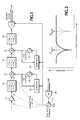
- Frequency spurs i.e., frequency spectra unrelated to a received signal to be measured caused by sources within a radio frequency receiver, such as the reference frequency in a synthesized measurement receiver, are a constant problem to RF designers. Combining the effects of the reference's high amplitude with its tendency to create many harmonics means that this signal may leak into the receiver's front end, as shown in Fig. 1. This creates spurs when the receiver is tuned to any frequency near one of those harmonics. Up until now the hardware designer had to perfect the hardware's shielding to the point that the spur is suppressed below the receiver's noise floor.
- h is an integer indicating the harmonic order of F ref , while m and n may be either integer or rational, i.e., the ratio of two integer numbers.
- What is desired is a method of canceling the spur in a frequency spectrum of a signal caused by a reference frequency used in a synthesized measurement radio frequency receiver.
- the present invention provides a method of reference frequency spur cancellation in a synthesized radio frequency receiver by determining values of an integer multiplier that cause the reference frequency to leak into the input signal path for known frequencies of the local oscillators derived from the reference frequency. For those integer values that cause such leakage, the amplitude and phase of the spurs are estimated in the digital domain and subtracted from the input signal. This removes signals from a narrow range of frequencies near spurs. To maintain the input signal at frequencies near spurs, the process is repeated with the reference frequency offset slightly, and the maximum values from the two measurement results provide the measurement of the input signal.
- Fig. 1 is a block diagram view of a portion of a synthesized measurement radio frequency receiver.
- Fig. 2 is a graphic view of a frequency spectrum illustrating spur cancellation according to the present invention.
- an input signal is pre-processed by an amplifier 12 and lowpass filtered by an input filter 14.
- the pre-processed input signal is then input to a first mixer 16, filtered by a first IF filter 18, input to a second mixer 20 and filtered by a second IF filter 22 before being digitized by an A/D converter 24 for input to a DSP for digital signal processing.
- the frequencies of first and second local oscillators (LO1 and LO2) 24, 26 are generated from respective synthesizers 28, 30 which in turn are clocked from a reference frequency source 32 controlled by the output of D/A converter 34 having a control signal input from the DSP.
- the frequency of spurs caused by leakage of the reference frequency signal from the source 32 into the front end amplifier 12, lowpass filter 14 and first mixer 16 are known exactly, i.e., the source making the spur is the same one providing the reference frequency to tune the local oscillators 24, 26.
- the front end processed input signal including any spurs is in the digital domain it is a straight forward process to closely estimate the spurs' amplitude and phase since the spurs are simple, sine wave tones as the reference frequency is not modulated.
- the spurs then may be simply subtracted from the digitized signal, removing them from the measurement of the input signal. In principle this is true in any synthesized receiver, even those using analog final signal processing. In an analog receiver a negative version of the spur's IF signal is added to the signal instead of subtracting as in the digital receiver. But in a practical realization a digital signal processor-based final signal processing is required to obtain sufficient accuracy to make the process work well.
- the harmonic of the reference frequency itself is the spur signal, and all subsequent frequency conversions in the first and second mixers 16, 20 are dependent on the reference frequency.
- n and m are well known.
- the bandwidths of the IF filters 18, 22 are known so that it is easy to determine a short list of the values of n and m that cause the receiver to tune to a reference harmonic h.
- a reference frequency 32 of 60 MHz directly clocks the A/D converter as well as provides the reference frequency for the synthesizers 28, 30.
- the second LO's synthesizer 30 sets the second LO 26 to exactly 60 times the reference frequency, or 3600 MHz.
- the DSP process plus the second IF filter 22 limit the range of signals that affect the receiver's output to 45 MHz +/- 5 MHz. If a spur caused by the reference frequency falls in this range, it is a problem.
- the 3600 MHz second LO translates this frequency range to 3645 MHz +/- 5 MHz in the first IF filter 18. Considering the first harmonic of the reference at 60 MHz, and first LO frequency that translates this frequency to 3645 MHz +/- 5 MHz causes the reference spur problem.
- the frequency of the digital representation of the spurious signal(s) caused by the reference frequency is perfectly known based on the frequency to which the receiver is tuned.
- the phase and amplitude of any given spur are not known - the amplitude because of the variability of the signal amplitude and leakage path loss as a function of frequency; and the phase primarily because of the uncertainty of the state of the various synthesizers 28, 30.
- SpurPhasorEstimate A + jB
- x(n) x re (n) + j*x im (n). This amounts to translating the complex spur component to 0 Hz and averaging the samples, i.e., lowpass filtering, to get the mean phasor value.
- the spurious signal may be numerically
- the bandwidth of this process may be made essentially zero.
- the probability of finding and eliminating a legitimate, i.e., non-spurious, input signal at exactly the reference frequency is very small.
- the measurement record lengths used are limited. Therefore if there is a legitimate signal at a similar or higher amplitude than the spurious signal and near it in frequency, it may be partially or fully subtracted from the input signal by this process, as shown for Spur1 in Fig. 2.
- the reference frequency is made tunable over a narrow frequency range.
- the first spur is estimated and subtracted from the signal leaving a measurement uncertainty near its frequency, as shown by the solid curve.
- This frequency distance is known from prior calibration of the reference frequency source's tuning characteristic. Based on this knowledge the frequency scale of the second measurement is processed to also remove the spur from this measurement and then offset to place the data correct on the frequency axis as shown by the dotted curve.
- the present invention provides reference spur cancellation in a synthesized measurement receiver by determining, with known multipliers for the reference frequency to produce local oscillator frequencies, a list of integers that cause the reference frequency to leak into the input signal path as spurious signals, by estimating the amplitude and phase of the spurs in the digital domain to subtract them from the input signal, by repeating the measurement with the frequency of the reference frequency offset slightly, and by providing an output that is the maximum amplitude between the two measurements as the measurement of the input signal without spurs.
Landscapes
- Engineering & Computer Science (AREA)
- Computer Networks & Wireless Communication (AREA)
- Signal Processing (AREA)
- Noise Elimination (AREA)
- Superheterodyne Receivers (AREA)
Abstract
Description
| n | FLO1 | FIF1 | FIF2 | FDIF | FDigital |
| 1851 | 3702 | 3642 | 42 | 18 | 0.3000 |
| 1852 | 3704 | 3644 | 44 | 16 | 0.2667 |
| 1853 | 3706 | 3646 | 46 | 14 | 0.2333 |
| 1854 | 3706 | 3648 | 48 | 12 | 0.2000 |
the spur from this measurement and then offset to place the data correct on the frequency axis as shown by the dotted curve.
Claims (3)
- A method of reference frequency spur cancellation in a synthesized measurement receiver comprising the steps of:for a given frequency to which the receiver is tuned determining a list of values of an integer multiplier for the reference frequency that cause a spurious signal in an input signal path;estimating in the digital domain amplitude and phase for the spurious signal; andsubtracting the amplitude and phase of the spurious signal from the input signal to provide a measurement of the input signal without the spurious signal.
- The method as recited in claim 1 further comprising the steps of:repeating the determining, estimating and subtracting steps with the frequency of the reference frequency offset slightly to provide a second measurement of the input signal without the spurious signal; andcombining the measurements of the input signal from the two iterations to produce the measurement of the input signal without the spurious signals.
- The method as recited in claim 2 wherein the combining step comprises the step of taking the maximum between the two measurements to produce the measurement of the input signal.
Applications Claiming Priority (2)
| Application Number | Priority Date | Filing Date | Title |
|---|---|---|---|
| US826495 | 2001-04-04 | ||
| US09/826,495 US6384589B1 (en) | 2001-04-04 | 2001-04-04 | Reference frequency spur cancellation in synthesized measurement receivers |
Publications (3)
| Publication Number | Publication Date |
|---|---|
| EP1248395A2 true EP1248395A2 (en) | 2002-10-09 |
| EP1248395A3 EP1248395A3 (en) | 2004-08-04 |
| EP1248395B1 EP1248395B1 (en) | 2007-11-28 |
Family
ID=25246684
Family Applications (1)
| Application Number | Title | Priority Date | Filing Date |
|---|---|---|---|
| EP02252429A Expired - Lifetime EP1248395B1 (en) | 2001-04-04 | 2002-04-03 | Reference frequency spur cancellation in synthesized measurement receivers |
Country Status (4)
| Country | Link |
|---|---|
| US (1) | US6384589B1 (en) |
| EP (1) | EP1248395B1 (en) |
| JP (1) | JP3610343B2 (en) |
| DE (1) | DE60223745T2 (en) |
Cited By (1)
| Publication number | Priority date | Publication date | Assignee | Title |
|---|---|---|---|---|
| US9391667B2 (en) | 2013-07-05 | 2016-07-12 | Telefonaktiebolaget Lm Ericsson (Publ) | Cancellation of spurious responses from local oscillator cross-coupling |
Families Citing this family (13)
| Publication number | Priority date | Publication date | Assignee | Title |
|---|---|---|---|---|
| DE102004050912B4 (en) * | 2004-04-05 | 2009-09-10 | Rohde & Schwarz Gmbh & Co. Kg | Method and device for increasing the dynamic range and the measuring accuracy of a measuring device for spectrum and / or network analysis |
| JP4806523B2 (en) * | 2004-09-02 | 2011-11-02 | 株式会社アドバンテスト | Signal mixing apparatus, method, program, recording medium, and spectrum analyzer |
| EP1648093B1 (en) | 2004-10-15 | 2011-08-03 | Broadcom Corporation | Spur harmonic canceller for RF band clock |
| US7250887B2 (en) * | 2004-10-25 | 2007-07-31 | Broadcom Corporation | System and method for spur cancellation |
| JP5103710B2 (en) * | 2005-04-22 | 2012-12-19 | 横河電機株式会社 | High frequency signal measuring instrument |
| JP2008111832A (en) * | 2006-10-03 | 2008-05-15 | Advantest Corp | Spectrum analyzer, spectrum analysis method and program |
| US8238480B2 (en) * | 2007-10-05 | 2012-08-07 | Motorola Mobility Llc | Adaptive self-quieter suppression for OFDM wireless communication systems |
| US8121569B2 (en) * | 2008-09-30 | 2012-02-21 | Intel Corporation | Frequency generation techniques |
| JP5512966B2 (en) * | 2008-12-25 | 2014-06-04 | 京セラ株式会社 | Wireless communication device |
| DE102019117264A1 (en) * | 2019-06-26 | 2020-12-31 | Intel Corporation | Method and apparatus for suppressing interference in a transceiver |
| US12072361B2 (en) * | 2021-03-10 | 2024-08-27 | Keysight Technologies, Inc. | Methods, devices, and systems for coherent time-gated residual spur characterization and correction in signal analyzers |
| US11811440B2 (en) | 2021-05-21 | 2023-11-07 | Rockwell Collins, Inc. | System and method for cancelation of internally generated spurious signals in a broadband radio receiver |
| CN113437965B (en) * | 2021-08-10 | 2022-03-25 | 新港海岸(北京)科技有限公司 | Spurious signal elimination circuit and method |
Family Cites Families (4)
| Publication number | Priority date | Publication date | Assignee | Title |
|---|---|---|---|---|
| US4918382A (en) * | 1989-03-20 | 1990-04-17 | Tektronix, Inc. | Method for distinguishing between real and spurious responses in a spectrum analyzer |
| US5493210A (en) * | 1993-06-10 | 1996-02-20 | Trilithic, Inc. | Combined signal level meter and leakage detector |
| US6192228B1 (en) * | 1998-09-11 | 2001-02-20 | Conexant Systems, Inc. | Method and apparatus for improving the sensitivity of an RF receiver at certain frequencies |
| SE512979C2 (en) * | 1998-10-23 | 2000-06-12 | Ericsson Telefon Ab L M | Apparatus and method for attenuation of electromagnetic interference |
-
2001
- 2001-04-04 US US09/826,495 patent/US6384589B1/en not_active Expired - Fee Related
-
2002
- 2002-04-01 JP JP2002099008A patent/JP3610343B2/en not_active Expired - Fee Related
- 2002-04-03 EP EP02252429A patent/EP1248395B1/en not_active Expired - Lifetime
- 2002-04-03 DE DE60223745T patent/DE60223745T2/en not_active Expired - Fee Related
Cited By (1)
| Publication number | Priority date | Publication date | Assignee | Title |
|---|---|---|---|---|
| US9391667B2 (en) | 2013-07-05 | 2016-07-12 | Telefonaktiebolaget Lm Ericsson (Publ) | Cancellation of spurious responses from local oscillator cross-coupling |
Also Published As
| Publication number | Publication date |
|---|---|
| EP1248395A3 (en) | 2004-08-04 |
| DE60223745D1 (en) | 2008-01-10 |
| JP2002359573A (en) | 2002-12-13 |
| EP1248395B1 (en) | 2007-11-28 |
| DE60223745T2 (en) | 2008-11-20 |
| JP3610343B2 (en) | 2005-01-12 |
| US6384589B1 (en) | 2002-05-07 |
Similar Documents
| Publication | Publication Date | Title |
|---|---|---|
| US6384589B1 (en) | Reference frequency spur cancellation in synthesized measurement receivers | |
| US6330290B1 (en) | Digital I/Q imbalance compensation | |
| US7142835B2 (en) | Apparatus and method for digital image correction in a receiver | |
| US20040152436A1 (en) | Systems and methods for coherent adaptive calibration in a receiver | |
| KR20010032300A (en) | Methods of suppressing reference oscillator harmonic interference and related receivers | |
| US6304751B1 (en) | Circuits, systems and methods for digital correction of phase and magnitude errors in image reject mixers | |
| MXPA04007040A (en) | System and method for i-q mismatch compensation in a low if or zero if receiver. | |
| US20090286499A1 (en) | High dynamic range receiver | |
| KR100218075B1 (en) | Coherent a/d converter and the method | |
| EP1172928A2 (en) | DC offset correction circuit and AGC in zero-if wireless receivers | |
| EP1248360A2 (en) | Multi-Frequency-Converter with spur avoidance | |
| US6259253B1 (en) | MRI transceiver | |
| US7373119B2 (en) | Method and apparatus for analog-to-digital conversion | |
| US6297637B1 (en) | High-frequency receiver, particularly for a nuclear magnetic resonance apparatus | |
| EP0841569B1 (en) | A spectrum analyser | |
| JP2003149279A (en) | Network analyzer and RF measurement method | |
| US8135372B2 (en) | Integrated cancellation circuit for RF converter spurious tones | |
| US20110019773A1 (en) | Signal processing circuit and method with frequency up-and down-conversion | |
| US11177846B2 (en) | Radio frequency circuits and methods of processing radio frequency signals | |
| RU2100821C1 (en) | Receiver for user equipment of global satellite navigation system | |
| RU2067770C1 (en) | User set receiver for signals from global satellite navigation systems | |
| US9432236B2 (en) | System for generating a calibration signal, related transceiver and method | |
| Pierre et al. | Considerations in the autocalibration of quadrature receivers | |
| Mavric et al. | Multi-channel down-conversion for MicroTCA. 4 based control systems | |
| CN118444038B (en) | Phase noise measurement method, device, spectrum analyzer and storage medium |
Legal Events
| Date | Code | Title | Description |
|---|---|---|---|
| PUAI | Public reference made under article 153(3) epc to a published international application that has entered the european phase |
Free format text: ORIGINAL CODE: 0009012 |
|
| AK | Designated contracting states |
Kind code of ref document: A2 Designated state(s): AT BE CH CY DE DK ES FI FR GB GR IE IT LI LU MC NL PT SE TR |
|
| AX | Request for extension of the european patent |
Free format text: AL;LT;LV;MK;RO;SI |
|
| PUAL | Search report despatched |
Free format text: ORIGINAL CODE: 0009013 |
|
| AK | Designated contracting states |
Kind code of ref document: A3 Designated state(s): AT BE CH CY DE DK ES FI FR GB GR IE IT LI LU MC NL PT SE TR |
|
| AX | Request for extension of the european patent |
Extension state: AL LT LV MK RO SI |
|
| RIC1 | Information provided on ipc code assigned before grant |
Ipc: 7H 04B 15/04 B Ipc: 7H 04B 1/12 B Ipc: 7H 04B 1/28 A |
|
| 17P | Request for examination filed |
Effective date: 20041108 |
|
| AKX | Designation fees paid |
Designated state(s): DE FR GB |
|
| 17Q | First examination report despatched |
Effective date: 20050510 |
|
| GRAP | Despatch of communication of intention to grant a patent |
Free format text: ORIGINAL CODE: EPIDOSNIGR1 |
|
| GRAS | Grant fee paid |
Free format text: ORIGINAL CODE: EPIDOSNIGR3 |
|
| GRAA | (expected) grant |
Free format text: ORIGINAL CODE: 0009210 |
|
| AK | Designated contracting states |
Kind code of ref document: B1 Designated state(s): DE FR GB |
|
| REF | Corresponds to: |
Ref document number: 60223745 Country of ref document: DE Date of ref document: 20080110 Kind code of ref document: P |
|
| ET | Fr: translation filed | ||
| PLBE | No opposition filed within time limit |
Free format text: ORIGINAL CODE: 0009261 |
|
| STAA | Information on the status of an ep patent application or granted ep patent |
Free format text: STATUS: NO OPPOSITION FILED WITHIN TIME LIMIT |
|
| 26N | No opposition filed |
Effective date: 20080829 |
|
| PGFP | Annual fee paid to national office [announced via postgrant information from national office to epo] |
Ref country code: DE Payment date: 20090422 Year of fee payment: 8 Ref country code: FR Payment date: 20090414 Year of fee payment: 8 |
|
| PGFP | Annual fee paid to national office [announced via postgrant information from national office to epo] |
Ref country code: GB Payment date: 20090421 Year of fee payment: 8 |
|
| GBPC | Gb: european patent ceased through non-payment of renewal fee |
Effective date: 20100403 |
|
| REG | Reference to a national code |
Ref country code: FR Ref legal event code: ST Effective date: 20101230 |
|
| PG25 | Lapsed in a contracting state [announced via postgrant information from national office to epo] |
Ref country code: DE Free format text: LAPSE BECAUSE OF NON-PAYMENT OF DUE FEES Effective date: 20101103 |
|
| PG25 | Lapsed in a contracting state [announced via postgrant information from national office to epo] |
Ref country code: GB Free format text: LAPSE BECAUSE OF NON-PAYMENT OF DUE FEES Effective date: 20100403 |
|
| PG25 | Lapsed in a contracting state [announced via postgrant information from national office to epo] |
Ref country code: FR Free format text: LAPSE BECAUSE OF NON-PAYMENT OF DUE FEES Effective date: 20100430 |