EP1248360A2 - Multi-Frequency-Converter with spur avoidance - Google Patents
Multi-Frequency-Converter with spur avoidance Download PDFInfo
- Publication number
- EP1248360A2 EP1248360A2 EP02252037A EP02252037A EP1248360A2 EP 1248360 A2 EP1248360 A2 EP 1248360A2 EP 02252037 A EP02252037 A EP 02252037A EP 02252037 A EP02252037 A EP 02252037A EP 1248360 A2 EP1248360 A2 EP 1248360A2
- Authority
- EP
- European Patent Office
- Prior art keywords
- frequency
- local oscillator
- intermediate frequency
- filter
- bandwidth
- Prior art date
- Legal status (The legal status is an assumption and is not a legal conclusion. Google has not performed a legal analysis and makes no representation as to the accuracy of the status listed.)
- Granted
Links
Images

Classifications
-
- H—ELECTRICITY
- H03—ELECTRONIC CIRCUITRY
- H03D—DEMODULATION OR TRANSFERENCE OF MODULATION FROM ONE CARRIER TO ANOTHER
- H03D7/00—Transference of modulation from one carrier to another, e.g. frequency-changing
- H03D7/16—Multiple-frequency-changing
- H03D7/161—Multiple-frequency-changing all the frequency changers being connected in cascade
Definitions
- the present invention relates to radio frequency receivers, and more particularly to a method of conversion spur avoidance in a multi-conversion radio frequency receiver.
- a multi-conversion radio frequency receiver may use multiple local oscillators when up-converting and down-converting a signal of interest. These separate local oscillators create sum and difference harmonic mixing products between themselves using the various nonlinear elements, primarily mixers and amplifiers, in the receiver. The amplitude of these harmonic mixing products depends on the conversion efficiency of the various elements at the harmonic mixing product frequencies.
- LO1 local oscillator
- IF1 intermediate frequency
- LO2 local oscillator
- What is desired is a method of conversion spur avoidance that predicts and avoids unwanted harmonic mixing products from multiple local oscillators in a multi-conversion radio frequency receiver.
- the present invention provides a method of conversion spur avoidance in a multi-conversion radio frequency receiver by predicting where conversion spurs may occur and retuning a second one of the local oscillators when the predicted conversion spur falls within an IF filter bandwidth of a first one of the local oscillators.
- a table of problem frequencies for the first local oscillator relative to a frequency of the second local oscillator which produce harmonic mixing products that fall within the bandwidth of the IF filter having a given center frequency IF1 is generated. For each problem frequency and a frequency offset is determined for the second local oscillator which moves the harmonic mixing product out of the IF filter bandwidth.
- the center frequency IF1 of the IF1 filter varies from receiver to receiver
- entries into the table are made for each possible IF1 frequency and during calibration of the receiver the IF1 frequency is precisely measured to determine the entries of the table to use during operation.
- the second local oscillator is retuned by the corresponding frequency offset from the table so the harmonic mixing product is moved out of the IF1 filter bandwidth.
- the direction of the frequency offset for the second local oscillator may be determined by which half of the IF filter bandwidth the harmonic mixing product falls.
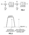
- a multi-conversion radio frequency receiver shown in Fig. 1 having at least two local oscillators LO1, LO2 for up-converting and down-converting a signal of interest via respective mixers M1, M2, is tuned to the first local oscillator frequency LO1 and a harmonic mixing product with the second local oscillator frequency LO2 occurs within the bandwidth of a first IF1 filter, the second local oscillator is retuned slightly to move the harmonic mixing product out of the IF1 filter bandwidth.
- the amount of retuning required depends on the order of the harmonic mixing product. The higher the order, the faster it moves with LO2 retuning.
- a harmonic mixing product appears in the IF1 filter bandwidth if the following equation is satisfied, as shown in Fig. 2: IF1 - IF1BW/2 # (N x LO1) ⁇ (M x LO2) # IF1 + IF1BW/2 where
- the first two steps of the algorithm may be performed as part of the design of the RF receiver and incorporated into the receiver's data processor and control software.
- the third step occurs during calibration of the receiver and is used as a pointer into the table for the appropriate entries to use during operation. If the variation from receiver to receiver in the IF1 center frequency is insignificant, the third step may be ignored and the first and second steps applied merely for the nominal IF1 frequency.
- the fourth step occurs operationally when input signals are being measured.
- the number of steps to move the LO2 frequency may be minimized by moving the LO2 frequency downward if the spur occurs in the first half of the IF1BW and upward if the spur occurs in the second half of the IF1BW rather than moving the LO2 frequency always in the same direction. This is especially significant for lower order harmonic mixing products where more steps are required to move the spur out of the IF1BW.
- the signal of interest is offset from nominal by the same amount that LO2 was adjusted. This requires that the second IF filter, if any, has a bandwidth wide enough to accommodate these variations, making it important to minimize the number of steps required to retune LO2 to minimize the bandwidth of the second IF filter.
- This method may be further applied to subsequent stages of conversion if required.
- the present invention provides a method of conversion spur avoidance in a multi-conversion radio frequency receiver by predicting when harmonic mixing products between a pair of local oscillators occurs within an IF filter bandwidth and the amount of frequency offset required to retune the second local oscillator to move the harmonic mixing products out of the IF filter bandwidth, and in operation if the first local oscillator is tuned to a frequency that produces such a harmonic mixing product, retuning the second local oscillator frequency by the frequency offset determined by the predicting step.
Landscapes
- Engineering & Computer Science (AREA)
- Power Engineering (AREA)
- Superheterodyne Receivers (AREA)
- Noise Elimination (AREA)
Abstract
Description
Claims (5)
- A method of conversion spur avoidance in a multi-conversion radio frequency receiver of the type having a first local oscillator, an intermediate frequency filter and a second local oscillator coupled in series for analyzing an input radio frequency signal comprising the steps of:generating for a nominal center frequency of the intermediate frequency filter a table of problem frequencies for the first local oscillator relative to a frequency of the second local oscillator that produce harmonic mixing products within the bandwidth of the intermediate frequency filter versus corresponding frequency offsets for the second local oscillator sufficient to move the harmonic mixing products outside the bandwidth of the intermediate frequency filter; andin operation when the first local oscillator is tuned to one of the problem frequencies, retuning the frequency of the second local oscillator according to the corresponding frequency offset from the table.
- The method as recited in claim 1 wherein the generating step further comprises generating the table for a range of center frequencies of the intermediate frequency filter.
- The method as recited in claim 2 further comprising the step of precisely measuring the center frequency of the intermediate frequency filter.
- The method as recited in claim 3 wherein the retuning step further comprises selecting the entries from the table as a function of the precisely measured center frequency of the intermediate frequency filter to select the problem frequencies and corresponding frequency offsets.
- The method as recited in claims 1, 2, 3, 4 or 5 wherein the polarity of the frequency offset is a function of which half of the bandwidth of the intermediate frequency filter the harmonic mixing product of the corresponding problem frequency falls.
Applications Claiming Priority (2)
| Application Number | Priority Date | Filing Date | Title |
|---|---|---|---|
| US09/825,308 US6785527B2 (en) | 2001-04-02 | 2001-04-02 | Conversion spur avoidance in a multi-conversion radio frequency receiver |
| US825308 | 2001-04-02 |
Publications (3)
| Publication Number | Publication Date |
|---|---|
| EP1248360A2 true EP1248360A2 (en) | 2002-10-09 |
| EP1248360A3 EP1248360A3 (en) | 2004-04-21 |
| EP1248360B1 EP1248360B1 (en) | 2006-08-30 |
Family
ID=25243664
Family Applications (1)
| Application Number | Title | Priority Date | Filing Date |
|---|---|---|---|
| EP02252037A Expired - Lifetime EP1248360B1 (en) | 2001-04-02 | 2002-03-21 | Multi-Frequency-Converter with spur avoidance |
Country Status (4)
| Country | Link |
|---|---|
| US (1) | US6785527B2 (en) |
| EP (1) | EP1248360B1 (en) |
| JP (1) | JP2002353836A (en) |
| DE (1) | DE60214271T2 (en) |
Cited By (3)
| Publication number | Priority date | Publication date | Assignee | Title |
|---|---|---|---|---|
| WO2004055995A3 (en) * | 2002-12-13 | 2004-08-26 | Microtune Texas Lp | System and method for discovering frequency related spurs in a multi-conversion tuner |
| GB2414351A (en) * | 2004-05-22 | 2005-11-23 | Zarlink Semiconductor Ltd | Controlling spurious heterodyne products in an arrangement of dual-conversion tuners |
| GB2518467A (en) * | 2013-09-23 | 2015-03-25 | Wistron Neweb Corp | Signal converter |
Families Citing this family (19)
| Publication number | Priority date | Publication date | Assignee | Title |
|---|---|---|---|---|
| DE60037722T2 (en) * | 2000-05-17 | 2009-01-15 | Sony Deutschland Gmbh | AM receiver |
| GB2402564B (en) * | 2003-06-07 | 2006-04-05 | Zarlink Semiconductor Ltd | Multiple conversion tuner |
| CA2467201A1 (en) * | 2004-05-13 | 2005-11-13 | Sirific Wireless Corporation | Dynamic and static spurious correction and control |
| US7783259B2 (en) * | 2004-09-28 | 2010-08-24 | Microtune (Texas), L.P. | System and method of eliminating or minimizing LO-related interference from tuners |
| US7904024B2 (en) * | 2004-09-28 | 2011-03-08 | Zoran Corporation | System and method of eliminating or minimizing Lo-Related interference from tuners |
| US20070229056A1 (en) * | 2006-03-31 | 2007-10-04 | Gorin Joseph M | Local oscillator diversity system for reducing spectrum analyzer synthesis spurs |
| US20090209222A1 (en) | 2008-02-15 | 2009-08-20 | Tektronix, Inc. | Conversion Architecture For Residual Spur Avoidance |
| JP2010011376A (en) * | 2008-06-30 | 2010-01-14 | Kddi Corp | Receiver using multiple bandwidths other than existing service bandwidths, program, and method |
| US20100323635A1 (en) * | 2009-06-23 | 2010-12-23 | Terry Steeper | Apparatus and methods for minimizing phase interaction between multiple tuner solutions |
| US8185078B2 (en) * | 2009-10-22 | 2012-05-22 | Anritsu Company | Dynamic spur avoidance for high speed receivers |
| FR2960363B1 (en) * | 2010-05-21 | 2012-05-18 | Thales Sa | BROADBAND FREQUENCY FLEXIBLE TRANSPOSITION DEVICE FOR SATELLITE REMOTE RECEIVER, AND ASSOCIATED RECEIVER |
| ES2428335T3 (en) * | 2010-12-22 | 2013-11-07 | Telefonaktiebolaget L M Ericsson (Publ) | Methods and receiver for positioning spurious signals related to a clock |
| US8750411B2 (en) * | 2011-06-30 | 2014-06-10 | Motorola Mobility Llc | Method and apparatus for reducing transmitter interference |
| US8594170B2 (en) | 2011-10-24 | 2013-11-26 | Sigear Europe Sarl | Clock masking scheme in a mixed-signal system |
| US8576951B2 (en) | 2011-10-24 | 2013-11-05 | Sigear Europe Sarl | Mixed-signal radio frequency receiver implementing multi-mode spur avoidance |
| WO2013062855A1 (en) * | 2011-10-24 | 2013-05-02 | Sigear Europe Sarl | Mixed-signal radio frequency receiver implementing multi-mode spur avoidance |
| JP6375217B2 (en) * | 2014-12-09 | 2018-08-15 | パナソニック株式会社 | RECEPTION DEVICE AND ITS CONTROL METHOD, SEMICONDUCTOR DEVICE, ELECTRONIC DEVICE, AND INSPECTION DEVICE |
| CN104811143B (en) * | 2015-03-17 | 2018-05-29 | 华为技术有限公司 | A kind of signal frequency conversion circuit and signal frequency conversion method |
| JP7677053B2 (en) * | 2021-08-06 | 2025-05-15 | 株式会社Jvcケンウッド | Receiving device |
Family Cites Families (16)
| Publication number | Priority date | Publication date | Assignee | Title |
|---|---|---|---|---|
| GB1526338A (en) | 1976-05-22 | 1978-09-27 | Eddystone Radio | Superheterodyne receivers |
| JPS55121740A (en) | 1979-03-14 | 1980-09-19 | Alps Electric Co Ltd | Television voice receiving tuner |
| US4395777A (en) | 1980-01-12 | 1983-07-26 | Sony Corporation | Double superheterodyne receiver |
| US4580289A (en) | 1981-12-30 | 1986-04-01 | Motorola, Inc. | Fully integratable superheterodyne radio receiver utilizing tunable filters |
| US4545072A (en) | 1982-02-22 | 1985-10-01 | Motorola, Inc. | Method and apparatus for eliminating interference due to spurious signals generated in synthesized receivers |
| US4512035A (en) | 1983-05-16 | 1985-04-16 | Motorola, Inc. | Method of programming a synthesizer ROM for elimination of receiver self-quieting |
| US4551856A (en) | 1983-05-16 | 1985-11-05 | Motorola, Inc. | Synthesized multiple conversion receiver system with provision for avoiding receiver self-quieting spurious response |
| US4661995A (en) | 1985-02-21 | 1987-04-28 | Anritsu Electric Co., Limited | Multi-superheterodyne receiver |
| US4879758A (en) | 1987-01-02 | 1989-11-07 | Motorola, Inc. | Communication receiver system having a decoder operating at variable frequencies |
| US5498998A (en) | 1992-11-16 | 1996-03-12 | Gehrke; James K. | Method for adjusting the output frequency of a frequency synthesizer |
| DE4306578C2 (en) | 1993-03-03 | 1995-08-24 | Loewe Opta Gmbh | Method and circuit arrangement for receiving RF signals using a double superimposed receiver |
| US5493210A (en) | 1993-06-10 | 1996-02-20 | Trilithic, Inc. | Combined signal level meter and leakage detector |
| JPH0746150A (en) | 1993-07-31 | 1995-02-14 | Nec Corp | Wireless selective call receiver |
| US5495206A (en) | 1993-10-29 | 1996-02-27 | Motorola, Inc. | Fractional N frequency synthesis with residual error correction and method thereof |
| US6002924A (en) | 1996-12-31 | 1999-12-14 | Aor, Ltd. | Full-spectrum all-mode radio receiver apparatus and method |
| US6308048B1 (en) | 1997-11-19 | 2001-10-23 | Ericsson Inc. | Simplified reference frequency distribution in a mobile phone |
-
2001
- 2001-04-02 US US09/825,308 patent/US6785527B2/en not_active Expired - Fee Related
-
2002
- 2002-03-21 EP EP02252037A patent/EP1248360B1/en not_active Expired - Lifetime
- 2002-03-21 DE DE60214271T patent/DE60214271T2/en not_active Expired - Lifetime
- 2002-04-01 JP JP2002099007A patent/JP2002353836A/en active Pending
Cited By (8)
| Publication number | Priority date | Publication date | Assignee | Title |
|---|---|---|---|---|
| WO2004055995A3 (en) * | 2002-12-13 | 2004-08-26 | Microtune Texas Lp | System and method for discovering frequency related spurs in a multi-conversion tuner |
| US7035614B2 (en) | 2002-12-13 | 2006-04-25 | Microtune (Texas), L.P. | System and method for discovering frequency related spurs in a multi-conversion tuner |
| US7764940B2 (en) | 2002-12-13 | 2010-07-27 | Microtune (Texas), L.P. | System and method for discovering frequency related spurs in a multi-conversion tuner |
| GB2414351A (en) * | 2004-05-22 | 2005-11-23 | Zarlink Semiconductor Ltd | Controlling spurious heterodyne products in an arrangement of dual-conversion tuners |
| GB2414351B (en) * | 2004-05-22 | 2006-04-12 | Zarlink Semiconductor Ltd | Tuner arrangement |
| US7437134B2 (en) | 2004-05-22 | 2008-10-14 | Intel Corporation | Tuner arrangement |
| GB2518467A (en) * | 2013-09-23 | 2015-03-25 | Wistron Neweb Corp | Signal converter |
| GB2518467B (en) * | 2013-09-23 | 2016-03-23 | Wistron Neweb Corp | Signal converter |
Also Published As
| Publication number | Publication date |
|---|---|
| EP1248360B1 (en) | 2006-08-30 |
| DE60214271T2 (en) | 2007-09-20 |
| US6785527B2 (en) | 2004-08-31 |
| US20020142748A1 (en) | 2002-10-03 |
| DE60214271D1 (en) | 2006-10-12 |
| EP1248360A3 (en) | 2004-04-21 |
| JP2002353836A (en) | 2002-12-06 |
Similar Documents
| Publication | Publication Date | Title |
|---|---|---|
| US6785527B2 (en) | Conversion spur avoidance in a multi-conversion radio frequency receiver | |
| US5952834A (en) | Low noise signal synthesizer and phase noise measurement system | |
| US6700531B2 (en) | Integrated multiple-up/down conversion radar test system | |
| US6057690A (en) | Automatic testing device for signal evaluation | |
| JP2002506525A (en) | Spectrum analyzer | |
| JPH08248070A (en) | Frequency spectrum analyzer | |
| JP2002506525A5 (en) | ||
| EP3422044B1 (en) | Frequency modulation circuit, fm-cw radar, and high-speed modulation radar | |
| US6233529B1 (en) | Frequency spectrum analyzer having time domain analysis function | |
| EP1248395B1 (en) | Reference frequency spur cancellation in synthesized measurement receivers | |
| US7880665B1 (en) | System and method for adaptation of a radar receiver in response to frequency drift in a transmission source | |
| JP4408967B2 (en) | Spectrum analyzer | |
| JP2011128021A (en) | Spectrum analyzer and spectrum analysis method | |
| JP4957678B2 (en) | Radio and control method | |
| US7747403B2 (en) | Method for measuring the phase jitter of a high-frequency signal and a measuring device for the implementation of this method | |
| US7209936B2 (en) | Frequency locked digitally tuned oscillator synthesizer | |
| US8718590B2 (en) | Downconversion of comb spectrum | |
| US7313492B2 (en) | Method and device for increasing the dynamic range and measuring accuracy of a measuring device for spectrum and/or network analysis | |
| EP2091143A2 (en) | Conversion architecture for residual spur avoidance | |
| US6384772B1 (en) | Wideband phase locking of low offset frequency sources | |
| JP2020094931A (en) | Frequency characteristic correcting device and frequency characteristic correction method | |
| CN100565224C (en) | It is used to distinguish the actual spectral line and image spectral line in the frequency converter of the spectrum analyzer | |
| US6963624B1 (en) | Method and apparatus for receiving radio frequency signals | |
| US6806746B1 (en) | Direct frequency synthesizer for offset loop synthesizer | |
| US4232263A (en) | Measuring installation for frequency analysis of signal levels within a large amplitude range |
Legal Events
| Date | Code | Title | Description |
|---|---|---|---|
| PUAI | Public reference made under article 153(3) epc to a published international application that has entered the european phase |
Free format text: ORIGINAL CODE: 0009012 |
|
| AK | Designated contracting states |
Kind code of ref document: A2 Designated state(s): AT BE CH CY DE DK ES FI FR GB GR IE IT LI LU MC NL PT SE TR |
|
| AX | Request for extension of the european patent |
Free format text: AL;LT;LV;MK;RO;SI |
|
| PUAL | Search report despatched |
Free format text: ORIGINAL CODE: 0009013 |
|
| AK | Designated contracting states |
Kind code of ref document: A3 Designated state(s): AT BE CH CY DE DK ES FI FR GB GR IE IT LI LU MC NL PT SE TR |
|
| AX | Request for extension of the european patent |
Extension state: AL LT LV MK RO SI |
|
| 17P | Request for examination filed |
Effective date: 20040601 |
|
| 17Q | First examination report despatched |
Effective date: 20040906 |
|
| AKX | Designation fees paid |
Designated state(s): DE FR GB |
|
| GRAP | Despatch of communication of intention to grant a patent |
Free format text: ORIGINAL CODE: EPIDOSNIGR1 |
|
| GRAS | Grant fee paid |
Free format text: ORIGINAL CODE: EPIDOSNIGR3 |
|
| GRAA | (expected) grant |
Free format text: ORIGINAL CODE: 0009210 |
|
| AK | Designated contracting states |
Kind code of ref document: B1 Designated state(s): DE FR GB |
|
| REG | Reference to a national code |
Ref country code: GB Ref legal event code: FG4D |
|
| RIN1 | Information on inventor provided before grant (corrected) |
Inventor name: EARLS, JEFFREY D. |
|
| REF | Corresponds to: |
Ref document number: 60214271 Country of ref document: DE Date of ref document: 20061012 Kind code of ref document: P |
|
| ET | Fr: translation filed | ||
| PLBE | No opposition filed within time limit |
Free format text: ORIGINAL CODE: 0009261 |
|
| STAA | Information on the status of an ep patent application or granted ep patent |
Free format text: STATUS: NO OPPOSITION FILED WITHIN TIME LIMIT |
|
| 26N | No opposition filed |
Effective date: 20070531 |
|
| PGFP | Annual fee paid to national office [announced via postgrant information from national office to epo] |
Ref country code: FR Payment date: 20120403 Year of fee payment: 11 |
|
| PGFP | Annual fee paid to national office [announced via postgrant information from national office to epo] |
Ref country code: DE Payment date: 20120323 Year of fee payment: 11 |
|
| PGFP | Annual fee paid to national office [announced via postgrant information from national office to epo] |
Ref country code: GB Payment date: 20120322 Year of fee payment: 11 |
|
| GBPC | Gb: european patent ceased through non-payment of renewal fee |
Effective date: 20130321 |
|
| REG | Reference to a national code |
Ref country code: FR Ref legal event code: ST Effective date: 20131129 |
|
| REG | Reference to a national code |
Ref country code: DE Ref legal event code: R119 Ref document number: 60214271 Country of ref document: DE Effective date: 20131001 |
|
| PG25 | Lapsed in a contracting state [announced via postgrant information from national office to epo] |
Ref country code: DE Free format text: LAPSE BECAUSE OF NON-PAYMENT OF DUE FEES Effective date: 20131001 Ref country code: GB Free format text: LAPSE BECAUSE OF NON-PAYMENT OF DUE FEES Effective date: 20130321 Ref country code: FR Free format text: LAPSE BECAUSE OF NON-PAYMENT OF DUE FEES Effective date: 20130402 |