EP1248345A2 - Voltage conversion apparatus - Google Patents
Voltage conversion apparatus Download PDFInfo
- Publication number
- EP1248345A2 EP1248345A2 EP02007566A EP02007566A EP1248345A2 EP 1248345 A2 EP1248345 A2 EP 1248345A2 EP 02007566 A EP02007566 A EP 02007566A EP 02007566 A EP02007566 A EP 02007566A EP 1248345 A2 EP1248345 A2 EP 1248345A2
- Authority
- EP
- European Patent Office
- Prior art keywords
- switching device
- switching
- drain
- voltage conversion
- source
- Prior art date
- Legal status (The legal status is an assumption and is not a legal conclusion. Google has not performed a legal analysis and makes no representation as to the accuracy of the status listed.)
- Withdrawn
Links
Images


Classifications
-
- H—ELECTRICITY
- H02—GENERATION; CONVERSION OR DISTRIBUTION OF ELECTRIC POWER
- H02M—APPARATUS FOR CONVERSION BETWEEN AC AND AC, BETWEEN AC AND DC, OR BETWEEN DC AND DC, AND FOR USE WITH MAINS OR SIMILAR POWER SUPPLY SYSTEMS; CONVERSION OF DC OR AC INPUT POWER INTO SURGE OUTPUT POWER; CONTROL OR REGULATION THEREOF
- H02M3/00—Conversion of DC power input into DC power output
- H02M3/02—Conversion of DC power input into DC power output without intermediate conversion into AC
- H02M3/04—Conversion of DC power input into DC power output without intermediate conversion into AC by static converters
- H02M3/10—Conversion of DC power input into DC power output without intermediate conversion into AC by static converters using discharge tubes with control electrode or semiconductor devices with control electrode
- H02M3/145—Conversion of DC power input into DC power output without intermediate conversion into AC by static converters using discharge tubes with control electrode or semiconductor devices with control electrode using devices of a triode or transistor type requiring continuous application of a control signal
- H02M3/155—Conversion of DC power input into DC power output without intermediate conversion into AC by static converters using discharge tubes with control electrode or semiconductor devices with control electrode using devices of a triode or transistor type requiring continuous application of a control signal using semiconductor devices only
- H02M3/156—Conversion of DC power input into DC power output without intermediate conversion into AC by static converters using discharge tubes with control electrode or semiconductor devices with control electrode using devices of a triode or transistor type requiring continuous application of a control signal using semiconductor devices only with automatic control of output voltage or current, e.g. switching regulators
- H02M3/158—Conversion of DC power input into DC power output without intermediate conversion into AC by static converters using discharge tubes with control electrode or semiconductor devices with control electrode using devices of a triode or transistor type requiring continuous application of a control signal using semiconductor devices only with automatic control of output voltage or current, e.g. switching regulators including plural semiconductor devices as final control devices for a single load
- H02M3/1582—Buck-boost converters
-
- H—ELECTRICITY
- H02—GENERATION; CONVERSION OR DISTRIBUTION OF ELECTRIC POWER
- H02J—ELECTRIC POWER NETWORKS; CIRCUIT ARRANGEMENTS OR SYSTEMS FOR SUPPLYING OR DISTRIBUTING ELECTRIC POWER; SYSTEMS FOR STORING ELECTRIC ENERGY
- H02J7/00—Circuit arrangements for charging or discharging batteries or for supplying loads from batteries
- H02J7/14—Circuit arrangements for charging or discharging batteries or for supplying loads from batteries for charging batteries from dynamo-electric generators driven at varying speed, e.g. on vehicle
-
- H—ELECTRICITY
- H02—GENERATION; CONVERSION OR DISTRIBUTION OF ELECTRIC POWER
- H02J—ELECTRIC POWER NETWORKS; CIRCUIT ARRANGEMENTS OR SYSTEMS FOR SUPPLYING OR DISTRIBUTING ELECTRIC POWER; SYSTEMS FOR STORING ELECTRIC ENERGY
- H02J7/00—Circuit arrangements for charging or discharging batteries or for supplying loads from batteries
- H02J7/34—Parallel operation in networks using both storage and other DC sources, e.g. providing buffering
- H02J7/345—Parallel operation in networks using both storage and other DC sources, e.g. providing buffering using capacitors as storage or buffering devices
Definitions
- the invention relates to a voltage conversion apparatus that performs voltage conversion between charging/discharging devices, such as batteries and capacitors. More particularly, the invention is concerned with a voltage conversion apparatus adapted to change a value or level of a voltage of a charging/discharging device, such as a battery or a capacitor, and apply the resulting voltage having a different value to another charging/discharging device.
- a charging/discharging device such as a battery or a capacitor
- the voltage conversion apparatus using the regeneration control there is known a step-up/step-down converter that performs charging and discharging of two condensers, as disclosed in Laid-open Publication No. 6-66204 of Utility Model Application.
- the step-up/step-down converter is constructed such that a reactor is connected to one of the condensers, and a switching device and a diode are connected between the output of the reactor and the earth (ground). In addition, a switching device and a diode are connected between the output of the reactor and the other condenser.
- a step-up operation the switching device connected between the output of the reactor and the other condenser is kept in the ON state, and the switching device connected between the output of the reactor and the earth is switched on and off, so that a high voltage is applied to the other condenser.
- a step-down operation on the other hand, the switching device connected between the output of the reactor and the other condenser is switched on and off, and the switching device connected between the output of the reactor and the earth is kept in the ON state, so that a low voltage is applied to the other condenser.
- step-up/step-down converter as described above has a problem of discontinuity in its operation when the voltage conversion ratio is in the vicinity of 1.
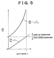
- the ratio of output voltage to input voltage in a step-up operation of the step-up/step-down converter is equal to 1/(1 - ⁇ ), where ⁇ represents switching duty ratio (T ON / (T ON + T OFF )) of the switching device.
- the ratio of output voltage to input voltage in a step-down operation of the converter is equal to ⁇ .
- Fig. 5 shows the relationship between the duty ratio ⁇ of the switching device and the ratio of the output voltage to the input voltage in step-up and step-down operations of the converter. As is understood from Fig. 5, the duty ratio ⁇ of the switching device needs to be changed when the step-up/step-down converter shifts from a step-down operation to a step-up operation, for example, resulting in discontinuity in the operation of the switching device.
- a voltage conversion apparatus which is connected between a first charging/discharging device and a second charging/discharging device and which performs voltage conversion between the first charging/discharging device and the second charging/discharging device.
- the voltage conversion apparatus includes: (a) a first switching device having a first terminal and a second terminal, the first terminal being connected to the first charging/discharging device, (b) a second switching device connected between the second terminal of the first switching device and the earth, (c) a third switching device having a third terminal and a fourth terminal, the third terminal being connected to the second charging/discharging device, (d) a fourth switching device connected between the fourth terminal of the third switching device and the earth, (e) a coil provided between the second terminal of the first switching device and the fourth terminal of the third switching device, and (f) a controller that controls operations of the first switching device, the second switching device, the third switching device and the fourth switching device, such that the first switching device and the fourth switching device are switched on and off in a first phase, and the second switching device and the third switching device are switched on and off in a second phase that is reverse to the first phase of switching of the first switching device and the fourth switching device.
- the first charging/discharging device is charged by use of braking energy of a vehicle.
- the operations of the first through fourth switching devices are controlled such that the first switching device and the fourth switching device are switched on and off in the same phase, and the second switching device and the third switching device are switched on and off in the same phase that is reverse to the phase of switching of the first and fourth switching devices.
- the four switching devices provide a step-up/step-down chopper in which a step-down chopper and a step-up chopper are connected in series.
- the thus constructed voltage conversion apparatus permits continuous switching from a step-up operation to a step-down operation, or vice versa, by continuously varying the duty ratio of switching of the switching devices. This arrangement makes it possible to avoid noise and false operations due to the noise, upon switching from a step-down operation to a step-up operation or vice versa.
- Fig. 1 schematically illustrates a voltage conversion apparatus according to a preferred embodiment of the invention.
- the voltage conversion apparatus 1 which is installed on a motor vehicle, performs voltage conversion between a condenser 3 that is to be charged by a generator 2, and a battery 4 (which will be described in detail later).
- the generator 2 serves to generate electric power, by using braking energy generated by an engine of the vehicle.
- the condenser 3 is connected between a positive terminal of the generator 2 and the earth (ground), and may be charged in accordance with an electric power generated by the generator 2.
- the condenser 3 may also be charged or discharged as needed through operations of the voltage conversion apparatus 1.
- the battery 4 serving as a voltage supply source for the vehicle is connected to a load 5, such as, for example, an air conditioner, which is installed on the vehicle and serves as a power consumer.
- the battery 4 is in the form of, for example, a storage battery, and is chargeable by an alternator (not shown).
- the battery 4 may also be charged and discharged as needed through operations of the voltage conversion apparatus 1.
- the voltage conversion apparatus 1 includes four FETs (Field Effect Transistors) 11 to 14, a controller 31, and a current sensor 32.
- the FETs 11 to 14 are switching devices that cause the voltage conversion apparatus 1 to operate as a step-up/step-down chopper.
- Each of the FETs 11 to 14 may be provided by, for example, a MOS type FET (MOSFET).
- the voltage conversion apparatus 1 further includes diodes 21 to 24, each of which is connected between a drain and a source of a corresponding one of the FETs 11 to 14. More specifically, a diode 21 is connected between a drain and a source of the FET 11, and a diode 22 is connected between a drain and a source of the FET 12. In addition, a diode 23 is connected between a drain and a source of the FET 13, and a diode 24 is connected between a drain and a source of the FET 14. The cathodes of the diodes 21 to 24 are respectively directed toward the drain sides of the corresponding FETs 11 to 14. Thus, the diodes 21 to 24 are oriented in the reverse direction as viewed from the drain toward the source of each FET such that current is allowed to flow only in a direction from the source to the drain of the FET.
- the drain of the FET 11 is connected to the generator 2 and the condenser 3.
- the source of the FET 11 is connected to the drain of the FET 12.
- the gate of the FET 11 is connected to the controller 31.
- the source of the FET 12 is grounded, and the gate of the FET 12 is connected to the controller 31.
- the drain of the FET 13 is connected to the battery 4 via the current sensor 32.
- the source of the FET 13 is connected to the drain of the FET 14.
- the gate of the FET 13 is connected to the controller 31.
- the source of the FET 14 is grounded, and the gate of the FET 14 is connected to the controller 31.
- the current sensor 32 functions to detect current supplied to the load 5.
- the voltage conversion apparatus 1 further includes a coil 41 that is connected between a point between the source of the FET 11 and the drain of the FET 12, and a point between the source of the FET 13 and the drain of the FET 14.
- the coil 41 functions as a smoothing reactor for smoothing voltage and current to be applied to, for example, the load 5.
- the controller 31 is adapted to control operations of the voltage conversion apparatus 1, and mainly includes a computer including, for example, CPU, ROM and RAM. Various control routines, such as a voltage conversion control routine, are stored in the ROM. The controller 31 transmits control signals to the respective gates of the FETs 11 to 14, to perform a voltage conversion control operation. The manner of transmitting the control signals to the FETs 11 to 14 will be described in detail when the operation of the voltage conversion apparatus 1 is explained.
- the controller 31 is also connected to the drain of the FET 11, and is able to detect a voltage at which the condenser 3 is charged. Furthermore, the controller 31 is connected to the drain of the FET 13, and is able to detect a voltage at which the battery 4 is charged.
- Fig. 2 is a timing chart showing an operation of the voltage conversion apparatus 1 according to the present embodiment.
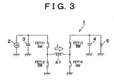
- Fig. 3 is a circuit diagram schematically showing the voltage conversion apparatus of the embodiment during its operation.
- the timing chart of Fig. 2 shows input signals that are applied from the controller 31 to the respective gates of the FETs 11 to 14.
- control signals are transmitted from the controller 31 to the gates of the FETs 11 to 14, respectively.
- Each of the control signals is in the form of a pulse signal that repeats ON/OFF switching (i.e., a rise and a decay of a pulse) at predetermined intervals, as shown in Fig. 2.
- the FET 11 and the FET 14, which are located diagonally with the coil 41 interposed therebetween, receive pulse signals of the same phase.
- the FET 12 and the FET 13, which are located diagonally with the coil 41 interposed therebetween receive pulse signals of the same phase that is reverse to that of the input pulse signals applied to the FET 11 and FET 14.
- the FET 11, FET 12 and the coil 41 constitute a step-down chopper, in which the FET 11 functions as a chopping portion of the step-down chopper.
- the FET 13, FET 14 and the coil 41 constitute a step-up chopper, in which the FET 14 functions as a chopping portion of the step-up chopper.
- the voltage conversion apparatus 1 as a whole functions as a step-up/step-down chopper, in which the step-up chopper is located behind (i.e., in the later stage of) the step-down chopper.
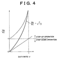
- the ratio of the voltage V B of the battery 4 to the voltage V C of the condenser 3 is equal to ⁇ / (1 - ⁇ ), where ⁇ represents a duty ratio of the pulse signals applied to the FET 11 and the FET 14.
- the voltage ratio (the ratio of the output voltage to the input voltage) V B /V C is equal to ⁇ / (1 - ⁇ ) during both a step-up operation and a step-down operation. Therefore, switching between the step-up operation and the step-down operation can be smoothly accomplished as the duty ratio ⁇ is continuously varied. This arrangement makes it possible to avoid noise and false operations due to the noise, upon switching from a step-down operation to a step-up operation or vice versa.
- the operations of the FETs 11 to 14 are controlled by switching on/off the FET 11 and the FET 14 in the same phase, and switching on/off the FET 12 and the FET 13 in the same phase that is reverse to the phase of switching of the FET 11 and the FET 14, as described above.
- the FETs 11 to 14 constitute a step-up/step-down chopper in which a step-down chopper and a step-up chopper are connected in series.
- the voltage conversion apparatus 1 is able to continuously shift or switch from a step-up operation to a step-down operation, or vice versa, by continuously varying the duty ratio ⁇ of switching of the FETs 11 to 14. This arrangement makes it possible to avoid noise and false operations due to the noise upon switching from a step-down operation to a step-up operation or vice versa.
- the voltage conversion apparatus of the illustrated embodiment is installed on a motor vehicle, such as an automobile, the invention may also be applied to voltage conversion apparatus for use in other applications.
- a voltage conversion apparatus (1) is connected between a first charging/discharging device (3) and a second charging/discharging device (4), and performs voltage conversion between the first and second charging/discharging devices.
- the apparatus includes a first switching device (11) having one terminal connected to the first charging/discharging device, a second switching device (12) connected between the other terminal of the first switching device and the earth, a third switching device (13) having one terminal connected to the second charging/discharging device, a fourth switching device (14) connected between the other terminal of the third switching device and the earth, and a coil provided between the other terminal of the first switching device and the other terminal of the third switching device.
- a controller (31) is provided for controlling the first through fourth switching devices, such that the first and fourth switching devices are switched on and off in the same phase, and the second and third switching devices are switched on and off in the same phase that is reverse to that of switching of the first and fourth switching devices.
Landscapes
- Engineering & Computer Science (AREA)
- Power Engineering (AREA)
- Dc-Dc Converters (AREA)
Abstract
Description
A voltage conversion apparatus (1) is connected between a first charging/discharging device (3) and a second charging/discharging device (4), and performs voltage conversion between the first and second charging/discharging devices. The apparatus includes a first switching device (11) having one terminal connected to the first charging/discharging device, a second switching device (12) connected between the other terminal of the first switching device and the earth, a third switching device (13) having one terminal connected to the second charging/discharging device, a fourth switching device (14) connected between the other terminal of the third switching device and the earth, and a coil provided between the other terminal of the first switching device and the other terminal of the third switching device. A controller (31) is provided for controlling the first through fourth switching devices, such that the first and fourth switching devices are switched on and off in the same phase, and the second and third switching devices are switched on and off in the same phase that is reverse to that of switching of the first and fourth switching devices. Selected Figure: Fig. 1
Claims (11)
- A voltage conversion apparatus (1) which is connected between a first charging/discharging device (3) and a second charging/discharging device (4) and which performs voltage conversion between the first charging/discharging device and the second charging/discharging device, characterized by comprising:a first switching device (11) having one terminal connected to the first charging/discharging device;a second switching device (12) connected between another terminal of the first switching device and ground;a third switching device (13) having one terminal connected to the second charging/discharging device;a fourth switching device (14) connected between another terminal of the third switching device and the ground;a coil (41) provided between said another terminal of the first switching device and said another terminal of the third switching device; anda controller (31) that controls operations of the first switching device, the second switching device, the third switching device and the fourth switching device, such that the first switching device and the fourth switching device are switched on and off in a first phase, and the second switching device and the third switching device are switched on and off in a second phase that is reverse to the first phase of switching of the first switching device and the fourth switching device.
- A voltage conversion apparatus according to claim 1, wherein the first charging/discharging device (3) is charged by use of braking energy of a vehicle.
- A voltage conversion apparatus according to claim 1 or claim 2, wherein each of the first, second, third and fourth switching devices comprises a field effect transistor having a drain, a source, and a gate, the gate is coupled to the controller to receive a control signal from the controller.
- A voltage conversion apparatus according to claim 3, further comprising a first diode (21) provided between a drain and a source of the first switching device, a second diode (22) provided between a drain and a source of the second switching device, a third diode (23) provided between a drain and a source of the third switching device, and a fourth diode (24) provided between a drain and a source of the fourth switching device.
- A voltage conversion apparatus according to claim 4, wherein each of the first, second, third and fourth diodes has a cathode that is directed toward the drain of a corresponding one of the first, second, third and fourth switching devices.
- A voltage conversion apparatus according to any one of claims 3-5, wherein said one terminal of the first switching device is the drain, said another terminal of the first switching device is the source, which is connected to the drain of the second switching device, and said one terminal of the third switching device is the drain, said another terminal of the third switching device is the source, which is connected to the drain of the fourth switching device.
- A voltage conversion apparatus which is connected between a first charging/discharging device (3) and a second charging/discharging device (4) and which performs voltage conversion between the first charging/discharging device and the second charging/discharging device, characterized by comprising:a first switching device (11) having a source and a drain, the drain being connected to the first charging/discharging device;a second switching device (12) having a drain connected to the source of the first switching device, the second switching device having a source connected to ground;a third switching device (13) having a source and a drain, the drain being connected to the second charging/discharging device;a fourth switching device (14) having a drain connected to the source of the third switching device, the fourth switching device having a source connected to the ground;a coil (41) provided between the source of the first switching device and the source of the third switching device; anda controller (31) that controls operations of the first switching device, the second switching device, the third switching device and the fourth switching device, such that the first switching device and the fourth switching device are switched on and off in a first phase, and the second switching device and the third switching device are switched on and off in a second phase that is reverse to the first phase of switching of the first switching device and the fourth switching device.
- A voltage conversion apparatus according to claim 7, wherein the first charging/discharging device is charged by use of braking energy of a vehicle.
- A voltage conversion apparatus according to claim 7 or claim 8, wherein each of the first, second, third and fourth switching devices comprises a field effect transistor having a gate, the gate is coupled to the controller to receive a control signal from the controller.
- A voltage conversion apparatus according to claim 9, further comprising a first diode (21) provided between the drain and the source of the first switching device, a second diode (22) provided between the drain and the source of the second switching device, a third diode (23) provided between the drain and the source of the third switching device, and a fourth diode (24) provided between the drain and the source of the fourth switching device.
- A voltage conversion apparatus according to claim 10, wherein each of the first, second, third and fourth diodes has a cathode that is directed toward the drain of a corresponding one of the first, second, third and fourth switching devices.
Applications Claiming Priority (2)
| Application Number | Priority Date | Filing Date | Title |
|---|---|---|---|
| JP2001106116A JP2002305875A (en) | 2001-04-04 | 2001-04-04 | Voltage converter |
| JP2001106116 | 2001-04-04 |
Publications (2)
| Publication Number | Publication Date |
|---|---|
| EP1248345A2 true EP1248345A2 (en) | 2002-10-09 |
| EP1248345A3 EP1248345A3 (en) | 2004-01-02 |
Family
ID=18958680
Family Applications (1)
| Application Number | Title | Priority Date | Filing Date |
|---|---|---|---|
| EP02007566A Withdrawn EP1248345A3 (en) | 2001-04-04 | 2002-04-03 | Voltage conversion apparatus |
Country Status (4)
| Country | Link |
|---|---|
| US (1) | US20020145898A1 (en) |
| EP (1) | EP1248345A3 (en) |
| JP (1) | JP2002305875A (en) |
| KR (1) | KR20020079366A (en) |
Cited By (10)
| Publication number | Priority date | Publication date | Assignee | Title |
|---|---|---|---|---|
| FR2853154A1 (en) * | 2003-03-27 | 2004-10-01 | Peugeot Citroen Automobiles Sa | Electrical energy supplying system for automobile, has consumer unit connected to electric network across auxiliary electrical energy source forming unit guided by controller to charge capacitor, where units are connected in series |
| EP1511149A3 (en) * | 2003-08-28 | 2006-06-07 | Delphi Technologies, Inc. | A power system to transfer power between a plurality of power sources |
| WO2006108020A1 (en) * | 2005-04-04 | 2006-10-12 | Aerovironment, Inc. | Energy storage apparatus and related method |
| WO2007048837A1 (en) * | 2005-10-27 | 2007-05-03 | Airbus France | Device for controlling power transfer between two cores of a direct current network |
| WO2007110016A1 (en) * | 2006-03-20 | 2007-10-04 | Temic Automotive Electric Motors Gmbh | Power supply circuit comprising a four-quadrant dc/dc converter for an automotive on-board power supply network |
| WO2008098812A1 (en) * | 2007-02-16 | 2008-08-21 | Siemens Ag Österreich | Current inverter |
| EP2081275A1 (en) * | 2008-01-15 | 2009-07-22 | Nisshinbo Industries, Inc. | Charging device |
| DE102008056604A1 (en) | 2008-11-10 | 2010-05-12 | Continental Automotive Gmbh | Supply network for windscreen heater in e.g. vehicle, has converter arranged for energy exchange between storages, where converter and storages are connected with one another such that voltages are available with respect to vehicle mass |
| FR2974956A1 (en) * | 2011-05-04 | 2012-11-09 | Peugeot Citroen Automobiles Sa | Electronic device for use as e.g. 12-volt battery charger in car, has control and regulation units for controlling opening and closing of MOSFETs based on given cyclic ratio, and for operating device as voltage booster or voltage converter |
| CN110168886A (en) * | 2016-12-21 | 2019-08-23 | 索尼公司 | Power Circuits and Electric Vehicles |
Families Citing this family (3)
| Publication number | Priority date | Publication date | Assignee | Title |
|---|---|---|---|---|
| JP4299570B2 (en) * | 2003-04-09 | 2009-07-22 | 新電元工業株式会社 | Power supply device and method of operating power supply device |
| JP5074993B2 (en) * | 2008-04-17 | 2012-11-14 | ヤンマー株式会社 | DC voltage buck-boost circuit |
| JP2011234485A (en) * | 2010-04-27 | 2011-11-17 | Honda Motor Co Ltd | Inverter type generator |
Family Cites Families (6)
| Publication number | Priority date | Publication date | Assignee | Title |
|---|---|---|---|---|
| JP3665419B2 (en) * | 1996-05-02 | 2005-06-29 | 新電元工業株式会社 | Inductive load driving method and H-bridge circuit control device |
| US5734258A (en) * | 1996-06-03 | 1998-03-31 | General Electric Company | Bidirectional buck boost converter |
| US5872703A (en) * | 1997-08-25 | 1999-02-16 | The Charles Machine Works, Inc. | System and method for regulating power in tank circuits having a bridge configuration |
| DE60040721D1 (en) * | 1999-08-03 | 2008-12-18 | Nxp Bv | UP / DOWN DC CONVERTER |
| US6243275B1 (en) * | 1999-09-28 | 2001-06-05 | Galaxy Power, Inc. | Dc to dc power converter using synchronously switched switches |
| US6246599B1 (en) * | 2000-08-25 | 2001-06-12 | Delta Electronics, Inc. | Constant frequency resonant inverters with a pair of resonant inductors |
-
2001
- 2001-04-04 JP JP2001106116A patent/JP2002305875A/en active Pending
-
2002
- 2002-01-04 KR KR1020020000395A patent/KR20020079366A/en not_active Ceased
- 2002-03-25 US US10/103,745 patent/US20020145898A1/en not_active Abandoned
- 2002-04-03 EP EP02007566A patent/EP1248345A3/en not_active Withdrawn
Cited By (16)
| Publication number | Priority date | Publication date | Assignee | Title |
|---|---|---|---|---|
| FR2853154A1 (en) * | 2003-03-27 | 2004-10-01 | Peugeot Citroen Automobiles Sa | Electrical energy supplying system for automobile, has consumer unit connected to electric network across auxiliary electrical energy source forming unit guided by controller to charge capacitor, where units are connected in series |
| EP1511149A3 (en) * | 2003-08-28 | 2006-06-07 | Delphi Technologies, Inc. | A power system to transfer power between a plurality of power sources |
| US7436150B2 (en) | 2005-04-04 | 2008-10-14 | Aerovironment Inc. | Energy storage apparatus having a power processing unit |
| WO2006108020A1 (en) * | 2005-04-04 | 2006-10-12 | Aerovironment, Inc. | Energy storage apparatus and related method |
| US7492130B2 (en) | 2005-04-04 | 2009-02-17 | Aerovironment, Inc. | Power processing unit and related method for regulating a voltage despite voltage fluctuations across an energy storage device |
| FR2892866A1 (en) * | 2005-10-27 | 2007-05-04 | Airbus France Sas | DEVICE FOR MONITORING POWER TRANSFER BETWEEN TWO HEADS OF A CONTINUOUS NETWORK |
| WO2007048837A1 (en) * | 2005-10-27 | 2007-05-03 | Airbus France | Device for controlling power transfer between two cores of a direct current network |
| US7671484B2 (en) | 2005-10-27 | 2010-03-02 | Airbus France | Device for controlling power transfer between two cores of a direct current network |
| RU2430456C2 (en) * | 2005-10-27 | 2011-09-27 | Эрбюс Франс | Device to control power transmission between two dc circuit stations |
| WO2007110016A1 (en) * | 2006-03-20 | 2007-10-04 | Temic Automotive Electric Motors Gmbh | Power supply circuit comprising a four-quadrant dc/dc converter for an automotive on-board power supply network |
| WO2008098812A1 (en) * | 2007-02-16 | 2008-08-21 | Siemens Ag Österreich | Current inverter |
| EP2081275A1 (en) * | 2008-01-15 | 2009-07-22 | Nisshinbo Industries, Inc. | Charging device |
| DE102008056604A1 (en) | 2008-11-10 | 2010-05-12 | Continental Automotive Gmbh | Supply network for windscreen heater in e.g. vehicle, has converter arranged for energy exchange between storages, where converter and storages are connected with one another such that voltages are available with respect to vehicle mass |
| DE102008056604B4 (en) * | 2008-11-10 | 2011-02-03 | Continental Automotive Gmbh | Supply network for switchable consumers, in particular high-performance consumers in vehicles |
| FR2974956A1 (en) * | 2011-05-04 | 2012-11-09 | Peugeot Citroen Automobiles Sa | Electronic device for use as e.g. 12-volt battery charger in car, has control and regulation units for controlling opening and closing of MOSFETs based on given cyclic ratio, and for operating device as voltage booster or voltage converter |
| CN110168886A (en) * | 2016-12-21 | 2019-08-23 | 索尼公司 | Power Circuits and Electric Vehicles |
Also Published As
| Publication number | Publication date |
|---|---|
| KR20020079366A (en) | 2002-10-19 |
| EP1248345A3 (en) | 2004-01-02 |
| JP2002305875A (en) | 2002-10-18 |
| US20020145898A1 (en) | 2002-10-10 |
Similar Documents
| Publication | Publication Date | Title |
|---|---|---|
| CA2412680C (en) | Hybrid vehicle and control method therefor | |
| US7122991B2 (en) | Power conversion and vehicle | |
| US6930460B2 (en) | Load driver with power storage unit | |
| US7407025B2 (en) | Power unit for automobile | |
| US7292462B2 (en) | DC/DC converter having transistor switches with flywheel diodes and program for controlling the transistor switches | |
| JP5126003B2 (en) | Vehicle control apparatus and control method | |
| KR100471093B1 (en) | Power supply device | |
| US6670788B2 (en) | Method and apparatus for maximizing hybrid vehicle energy management | |
| US8058743B2 (en) | Automotive electrical system for coupling power converters with a transformer | |
| EP1289106A1 (en) | DC-DC converter | |
| EP1248345A2 (en) | Voltage conversion apparatus | |
| US8076794B2 (en) | Multi-voltage vehicle electrical supply system for a motor vehicle and method for operating the same | |
| US20120069604A1 (en) | Compact power converter with high efficiency in operation | |
| US6812672B2 (en) | Electric charge control device and load driving device using the same | |
| JP2015534446A (en) | Power supply system with dual electrical energy storage device for automobile or hybrid vehicle | |
| US20100102635A1 (en) | Electrical system and automotive drive system having an on-demand boost converter, and related operating methods | |
| JP4454444B2 (en) | Bidirectional DC-DC converter | |
| JP2001128369A (en) | Power supply apparatus | |
| JP2011155837A (en) | Dc-dc converter and dc-dc converter system | |
| KR101602818B1 (en) | Torque Assist System for Mild Hybrid Vehicle | |
| JP2018050381A (en) | Vehicle power supply | |
| US10906484B2 (en) | In-vehicle power supply device | |
| EP2819290A2 (en) | Resonant bidirectional DC/DC converter with the same input and output electrical potential | |
| JP4871647B2 (en) | DC-DC converter and DC-DC converter system | |
| JP2022521419A (en) | Power electronics devices and methods for supplying voltage to the drive circuits of power semiconductor switches |
Legal Events
| Date | Code | Title | Description |
|---|---|---|---|
| PUAI | Public reference made under article 153(3) epc to a published international application that has entered the european phase |
Free format text: ORIGINAL CODE: 0009012 |
|
| 17P | Request for examination filed |
Effective date: 20020403 |
|
| AK | Designated contracting states |
Kind code of ref document: A2 Designated state(s): AT BE CH CY DE DK ES FI FR GB GR IE IT LI LU MC NL PT SE TR |
|
| AX | Request for extension of the european patent |
Free format text: AL;LT;LV;MK;RO;SI |
|
| PUAL | Search report despatched |
Free format text: ORIGINAL CODE: 0009013 |
|
| AK | Designated contracting states |
Kind code of ref document: A3 Designated state(s): AT BE CH CY DE DK ES FI FR GB GR IE IT LI LU MC NL PT SE TR |
|
| AX | Request for extension of the european patent |
Extension state: AL LT LV MK RO SI |
|
| STAA | Information on the status of an ep patent application or granted ep patent |
Free format text: STATUS: THE APPLICATION HAS BEEN WITHDRAWN |
|
| 18W | Application withdrawn |
Effective date: 20040429 |