EP1248343A2 - Modular architecture for industrial power delivery system - Google Patents
Modular architecture for industrial power delivery system Download PDFInfo
- Publication number
- EP1248343A2 EP1248343A2 EP20020001374 EP02001374A EP1248343A2 EP 1248343 A2 EP1248343 A2 EP 1248343A2 EP 20020001374 EP20020001374 EP 20020001374 EP 02001374 A EP02001374 A EP 02001374A EP 1248343 A2 EP1248343 A2 EP 1248343A2
- Authority
- EP
- European Patent Office
- Prior art keywords
- power
- module
- output
- digital
- sensor
- Prior art date
- Legal status (The legal status is an assumption and is not a legal conclusion. Google has not performed a legal analysis and makes no representation as to the accuracy of the status listed.)
- Withdrawn
Links
Images


Classifications
-
- H—ELECTRICITY
- H02—GENERATION; CONVERSION OR DISTRIBUTION OF ELECTRIC POWER
- H02J—ELECTRIC POWER NETWORKS; CIRCUIT ARRANGEMENTS OR SYSTEMS FOR SUPPLYING OR DISTRIBUTING ELECTRIC POWER; SYSTEMS FOR STORING ELECTRIC ENERGY
- H02J1/00—Circuit arrangements for DC mains or DC distribution networks
- H02J1/10—Parallel operation of DC sources
- H02J1/102—Parallel operation of DC sources being switching converters
-
- G—PHYSICS
- G05—CONTROLLING; REGULATING
- G05B—CONTROL OR REGULATING SYSTEMS IN GENERAL; FUNCTIONAL ELEMENTS OF SUCH SYSTEMS; MONITORING OR TESTING ARRANGEMENTS FOR SUCH SYSTEMS OR ELEMENTS
- G05B23/00—Testing or monitoring of control systems or parts thereof
- G05B23/02—Electric testing or monitoring
-
- H—ELECTRICITY
- H02—GENERATION; CONVERSION OR DISTRIBUTION OF ELECTRIC POWER
- H02M—APPARATUS FOR CONVERSION BETWEEN AC AND AC, BETWEEN AC AND DC, OR BETWEEN DC AND DC, AND FOR USE WITH MAINS OR SIMILAR POWER SUPPLY SYSTEMS; CONVERSION OF DC OR AC INPUT POWER INTO SURGE OUTPUT POWER; CONTROL OR REGULATION THEREOF
- H02M3/00—Conversion of DC power input into DC power output
- H02M3/22—Conversion of DC power input into DC power output with intermediate conversion into AC
- H02M3/24—Conversion of DC power input into DC power output with intermediate conversion into AC by static converters
- H02M3/28—Conversion of DC power input into DC power output with intermediate conversion into AC by static converters using discharge tubes with control electrode or semiconductor devices with control electrode to produce the intermediate AC
- H02M3/325—Conversion of DC power input into DC power output with intermediate conversion into AC by static converters using discharge tubes with control electrode or semiconductor devices with control electrode to produce the intermediate AC using devices of a triode or a transistor type requiring continuous application of a control signal
- H02M3/335—Conversion of DC power input into DC power output with intermediate conversion into AC by static converters using discharge tubes with control electrode or semiconductor devices with control electrode to produce the intermediate AC using devices of a triode or a transistor type requiring continuous application of a control signal using semiconductor devices only
- H02M3/33507—Conversion of DC power input into DC power output with intermediate conversion into AC by static converters using discharge tubes with control electrode or semiconductor devices with control electrode to produce the intermediate AC using devices of a triode or a transistor type requiring continuous application of a control signal using semiconductor devices only with automatic control of the output voltage or current, e.g. flyback converters
- H02M3/33515—Conversion of DC power input into DC power output with intermediate conversion into AC by static converters using discharge tubes with control electrode or semiconductor devices with control electrode to produce the intermediate AC using devices of a triode or a transistor type requiring continuous application of a control signal using semiconductor devices only with automatic control of the output voltage or current, e.g. flyback converters with digital control
Definitions
- the present invention relates generally to industrial power delivery systems and, more particularly, to an industrial power delivery system having a modular architecture with digital communications links interconnecting the modules.
- RF radio frequency
- DC direct current
- Generating a power signal generally entails chopping and rectifying relatively high voltages, such as 270 Volts DC.
- the chopping and rectifying process generates spurious electric and magnetic fields that couple into nearby circuitry resulting in a relatively high electrical noise environment.
- the spurious fields that couple into data circuitry may cause a degradation in signal quality leading to possible data corruption.
- High-speed data communication lines are particularly susceptible to signal degradation and data corruption due to the relatively low noise signal amplitudes required for high speed communications.
- This invention is directed to a power generator system including a power module for receiving an electrical energy input and generating an electrical energy output, the power module includes a digital control input.
- a sensor module monitors the output of the power module.
- the sensor module includes a digital sensor output and generates a digital sensor signal on the digital sensor output that varies in accordance with the electrical energy output.
- a control module has a digital measurement input for receiving the sensor signal.
- the control module determines parameters that vary in accordance with the electrical energy output.
- the control module includes a digital control output connected to the digital control input.
- the control module generates a control signal applied to the digital control input for controlling the power module.
- This invention is also directed to a power delivery system that receives an input power and generates an output power to a load.
- the power delivery system includes a power generator which receives the input power and generates the output power.
- the power generator includes a first digital interface.
- An impedance matching network is interposed between the power generator and the load.
- the impedance match network including a second digital interface.
- An output sensor is disposed in proximity to the load and senses a parameter associated with the power generator output.
- the output sensor includes a third digital interface and generates a digital sensor signal via the third digital interface that varies in accordance with the sensed parameter.
- a controller receives the sensor signal and determines a control signal for output to the power generator.
- the controller includes a fourth digital interface and generates the control signal via the fourth digital interface for communications with the first digital interface.
- the power generator varies the output power in accordance with the control signal.
- Fig. 1 depicts a plasma control system 10 arranged in accordance with the principles of the present invention for controlling a plasma chamber 12.
- Plasma control system 10 includes a plasma chamber 12, such as may be used for fabricating integrated circuits.
- Plasma chamber 12 includes one or a plurality of gas inlets 14 and one or a plurality of gas outlets 16. Gas inlet 14 and gas outlet 16 enable the introduction and evacuation of gas from the interior of plasma chamber 12. The temperature within plasma chamber 12 may be controlled through a heat control signal 18 applied to plasma chamber 12.
- a plasma controller 20 receives inputs from the plasma chamber 12. These inputs include a vacuum signal 22 which indicates the level of vacuum in plasma chamber 12, a voltage signal 24, and a signal 26 indicating the ratio of flows between the inlet and the outlet gases. As one skilled in the art will recognize, other inputs/outputs may be received/generated by plasma controller 20.
- Plasma controller 20 determines a desired input power to be applied to plasma chamber 12 through a power delivery system 28, as will be described in greater detail herein.
- Power delivery system 28 outputs a predetermined electrical signal at a predetermined frequency and power rating. The voltage output from power delivery system 28 is applied to plasma chamber 12 in order supply sufficient energy to operate plasma chamber 12.
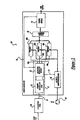
- Fig. 2 depicts a block diagram of power delivery system 28.
- Power delivery system 28 includes a delivery system 30 which includes a power generator or power generator module 32.
- Power generator 32 receives an input signal, such as an alternating current (AC) input signal from AC input/main housekeeping module 34. Power is received by AC input 34 through an AC receptacle 36.
- AC input 34 conditions the AC signal for application and input to power generator 32.
- Power generator 32 is embodied as any device which converts an input signal to a predetermined output signal.
- AC input 34 also converts the AC input signal to a low level direct current (DC) signal for powering logic level components.
- DC direct current
- power generator 32 is configured to output a radio frequency (RF) signal by converting the AC input to a predetermined DC voltage.
- a pair of switches such as a push pull amplifier configuration, in turn converts the DC voltage to an RF output voltage which may be filtered prior to output from power generator 32.
- the operation of power generator 32 may be any type of conventional operation known in the art, including single and two stage conversions.
- Power generator 32 generates an output voltage to an impedance match network or module 38 prior to application to a load 40.
- Impedance match module 38 typically provides a variable impedance between power generator 32 and load 40 in order to maintain a predetermined impedance at the output of power generator 32, typically 50 ohms.
- An output metrology module or output sensor 42 receives the power output from impedance match network 38 prior to application to load 40.
- Output sensor 42 measures predetermined parameters found in the output from impedance match network 38.
- output sensor 42 may measure one or a plurality of parameters including voltage, current, power, frequency, phase, or other parameters of interest in generating a power output to load 40.
- Both impedance match network 38 and output sensor 42 generate data signals to delivery system controller 44.
- Delivery system controller 44 receives data signals from one or both impedance match network 38 and output sensor 42. Delivery system controller 44 receives the data and generates at least one of a control or data signal to power generator 32, as will be described in greater detail herein. Delivery system controller 44 may also generate control signals to or exchange data with each of match network 38 and output sensor 42.
- Delivery system controller 44 also exchanges data and control signals with an input/output (I/O) adapter or adapter module 46, also known as a peripheral optional device (POD).
- I/O adapter 46 enables communications with external devices, such as an overall system controller, plasma system controller, test module, user input module, or other modules which may desire to share data with or control operation of delivery system 30.
- Delivery system controller 44 also exchanges data and control signals with AC input 34 to enable control of AC input 34.
- a particular feature of the subject invention is directed to communications between various modules of power delivery system 28. More specifically, delivery system controller 44 functions as a common controller core which interconnects system and subsystem modules via high speed, digital communications links 33, 35, 39, 43, and 47. These communications links enable single or bidirectional communications for data and control signals as design criteria dictates.
- Communications link 33 interconnects power delivery system 44 with delivery system controller 44 to enable high speed, bidirectional communications.
- Communications link 39 interconnects impedance match network 38 with delivery system controller 44 as required.
- Communications link 35 interconnects AC input 34 with delivery system controller 44.
- Communications link 43 interconnects output sensor 42 with delivery system controller 44 as required.
- Communications link 47 interconnects I/O adapter 46 with delivery system controller 44.
- Delivery system controller 44 communicates with each of power generator 32, impedance match network 38, output sensor 42, AC input 34, and I/O adapter 46 using a digital communications protocol, which preferably is a high speed digital communications protocol.
- the protocol may include error detection and correction to improve reliability of communications between system controller 44 and each device with which power controller 44 exchanges data. Such a protocol enables control and feedback signals to have a very high dynamic range compared to traditional analog methods for control and measurement.
- each module described herein may have a digital communications port, and each communications link functions cooperatively to define a digital interface between the connected modules to exchange data and control signals.
- power delivery system 44 communicates with the modules in a technology-independent manner across the communications links 33, 35, 39, 43, and 47 so that data may be encoded for communications between, for example, power delivery system controller 44 and impedance match network 38, output sensor 42, AC input 34, and I/O adapter 46. That is, data is exchanged using a protocol rather than traditional analog voltages, which can be sensitive to noise.
- the data communications between the respective modules transfer values rather than signal levels indicative of a value. For example, if output sensor 42 measures one or all of voltage, current, or power, output sensor 42 outputs a digital signal to indicate respective volts, amperes, or watts.
- the modules operate independently of methods used for determining these quantities. The modules simply determine the value of the quantity of interest. As an added benefit, the modules are redesigned, the redesigned modules may be substituted so long as they use the predetermined communications protocol.
- power generator 32 includes one or a plurality of modules interconnected using digital communication links 49a, 49b, 49c, 55, 51, and 61, which operate similarly to those described with respect to power delivery system 28 of Fig. 2. Power generator 32 is particularly directed to flexibility in providing power modules so that the power output of power generator 32 may be scaled in accordance with the particular design requirements. Power generator 32 includes a plurality of power modules 48a, 48b, 48c. Power modules 48 receive an input power from AC input/main housekeeping module 50, which operates as described above with respect to Fig. 2, and generates an output power. The output power is applied to combiner module 52.
- Combiner module 52 receives the respective outputs from power module 48a, 48b, and 48c and combines the outputs for application to sensor module 54.
- Sensor module 54 may operate similarly as described with respect to output sensor 42 of Fig. 2. More particularly, sensor module 54 may monitor particular parameters of the output power generated by power generator 32. That is, sensor module 54 senses parameters in the output power generated by power generator 32 prior to application to impedance match network 38 of Fig. 2. On the other hand, output sensor 42 measures predetermined parameters prior to application of the output power to load 40.
- Power generator 32 also includes a control module 57 including common controller core 56.
- Common controller core 56 operates as a local controller for power generator 32.
- Common controller core 56 is interconnected to an excitation/metrology module 58, which also forms part of control module 57.
- Control module 57 exchanges data and control commands with a predetermined, variable number of power modules 48, such as power modules 48a, 48b, 48c, sensor module 54, and AC input 50 via digital communications links 49a, 49b, 49c, 55, and 51.
- the number of power modules varies in accordance with the desired output of power generator 32.
- Control module 57 also exchanges data and control commands with I/O adapter 60 via digital communications link 61.
- Excitation/metrology module 58 receives data from sensor module 54 and general parameters of operation from common controller 56. Control module 57 and its components then generates control commands to operate each of respective power modules 48a, 48b, 48c in order to vary the power output from each power module 48a, 48b, 48c, prior to application to combiner module 52. Data may be exchanged between each of these modules as described above with respect to Fig. 2. In particular, excitation/metrology module 58 exchanges data with each of power modules 48a, 48b, 48c, sensor module 54, AC input 50, and I/O adapter 60 utilizing digital communications implementing any of a number of predetermined communications protocols.
- Fig. 4 depicts a block diagram of an alternative embodiment of power generator 32.
- the power generator 32 of Fig. 4 is similar to power generator 32 of Fig. 3 with the exception that power modules 48a, 48b, 48c do not all feed combiner module 52, as will be described in greater detail herein. Because of similarities between Figs. 3 and 4, like reference numerals from Fig. 3 will be used to refer to like elements in Fig. 4.
- Fig. 4 operate similarly as described in Fig. 3 with the exception that the outputs from each respective power module 48a, 48b, 48c, are combined to generate a pair of power outputs power output 1 and power output 2.
- Power module 1 48a provides an output to sensor module 54' which then provides power output 1.
- sensor module 54' may monitor particular perimeters of the output power generated by power module 1 48a.
- power module 2 48b and power module 3 48c provide respective outputs which are applied to combiner module 52.
- Combiner module 52 receives the respective outputs from power modules 48b and 48c and combines the outputs for application to sensor module 54".
- Sensor module 54" senses parameters in the output power generated by power generator 32 prior to application to impedance match network 38 of Fig. 2.
- Sensor module 54" provides an output signal on communications link 59 to excitation/metrology module 58, which operates as described above.
- Fig. 4 provides flexibility, such as may be required when power generator 32 must generate dual frequency outputs.
- power module 48a may output a first frequency
- power modules 48b and 48c may output a second frequency.
- power modules 48b and 48c are combined by combiner module to provide a higher power output at the second predetermined frequency.
- Power generators 32 of Figs. 3 and 4 may operate in conjunction with power delivery system 28 of Fig. 2. Alternatively, power generators 32 may operate independently and outside of a power delivery system to implement a less complex system. In such a configuration, power generators 32 may also include an I/O input/output adapter module 60 to enable communication with other devices as described above with respect to Fig. 2.
- Figs. 5 depicts a star network 66 having a plurality of modules M1 68, M2 70, M3 72, M4 74, and M5 76.
- a plurality of communications links interconnect each module with network controller or connector NC 78.
- communications link 80 interconnects module M1 68 with network controller NC 78.
- Communications link 82 interconnects module M2 70 with network controller NC 78.
- Communications link 84 interconnects module M3 72 with network controller NC 78.
- Communications link 86 interconnects module M4 74 with network controller NC 78.
- Communications link 88 interconnects module M5 76 with network controller NC 78.
- Star network 66 enables each respective module M1 through M5 to communication directly with each of another respective module through network controller NC 78.
- Fig. 5 depicts a network 90 having a plurality of modules M1 92, M2 94, M3 94, M3 96, M4 98, and M5 100.
- the modules of network 90 communicate directly and without the need for a network controller, as each module operates as a network controller.
- communications link 104 interconnects module M1 92 with module M2 94.
- Communications link 106 interconnects module M1 92 with module M3 96.
- Communications link 108 interconnects module M1 92 with module M4 98.
- Communications link 110 interconnects module M1 92 with module M5 100.
- Communications link 114 interconnects module M2 94 with module M3 96.
- Communications link 116 interconnect module M2 94 with module M4 98.
- Communication link 118 interconnects module M2 94 with module M5 100.
- Communications link 122 interconnects module M3 96 with module M4 98.
- Communications link 124 interconnects module M3 96 with module M5 100.
- Communications link 126 interconnects module M4 98 with module M5 100.
- Network 90 enables each respective module M1 through M5 to communication directly with each of another respective module.
- Each module M1 through M5 inherently functions as a network controller to select the best path between any two modules. Communications need not occur directly module to module and may occur through modules.
- module M1 92 may communication directly with module M4 98 through communications link 108.
- module M1 92 may communication with module M4 98 by first communicating with M2 94 through communications link 104.
- Module M2 94 may then communicate with module M4 98 through communications link 116.
- each module operates as if in an internet-type configuration.
- Fig. 7 depicts an alternate network configuration.
- Fig. 6 depicts a bus network 130 having modules M1 132, M2 134, and M3 136.
- the modules M1 132, M2 134, and M3 136 communicate via a bus 138.
- each module M1 132, M2 134, and M3 136 is addressable so that data may be exchanged via bus 138 using any of a number of bus addressing schemes.
- a plurality of communications links interconnect the modules to bus 138.
- communications link 140 interconnects module M1 132 to bus 138.
- Communications link 142 interconnects module M2 134 with bus 138.
- Communications link 144 interconnects module M3 136 with bus 138.
- the communication links described above are implemented utilizing single or multi-layer protocols, many of which are known in the art. Utilizing a multi-layer protocol enables substitution of modules and scalability of modules so long as each substituted or added module utilizes the particular layered protocol. Further, the communications links may be implemented using a number of known formats including low voltage differential (LVD), fiber optic cables, infrared transceivers, and wireless, radio communication techniques. Further yet, as discussed above, power generator 32 may be incorporated within power delivery system 28 or may operate independently of power delivery system 28.
- LDD low voltage differential
- power generator 32 may be incorporated within power delivery system 28 or may operate independently of power delivery system 28.
- the invention described herein provides a modular architecture for an industrial power delivery system which is both modular and scaleable.
- the power delivery system enables different features to be assembled independently of the technologies used in the modules. Accordingly, power delivery products with expanded or reduced capabilities can be produced much more quickly.
Landscapes
- Engineering & Computer Science (AREA)
- Power Engineering (AREA)
- Physics & Mathematics (AREA)
- General Physics & Mathematics (AREA)
- Automation & Control Theory (AREA)
- Supply And Distribution Of Alternating Current (AREA)
- Arrangements For Transmission Of Measured Signals (AREA)
- Cable Transmission Systems, Equalization Of Radio And Reduction Of Echo (AREA)
- Plasma Technology (AREA)
Abstract
A power generator (32) includes plural modules interconnected using digital communication links (49,5,55,61) and its power output can be scaled flexibly. Power modules (48) receive power from a housekeeping module (50) and pass their outputs to a combiner module (52) for combining the outputs for application to a sensor module (54), that may monitor the parameters of the output power, to form control feedbacks. An independent claim is included for a power generator system.
Description
- The present invention relates generally to industrial power delivery systems and, more particularly, to an industrial power delivery system having a modular architecture with digital communications links interconnecting the modules.
- Conventional power delivery systems are typically serviced by power supplies which are specifically designed for that particular application. These power supplies, however, lack modularity and flexibility for expansion in order to facilitate design and manufacture. Further, such power supplies do not typically include fault tolerant communications between modules. Further yet, such power supplies have limited redundancy and power handling capability.
- With reference to a specific application, material processing such as plasma deposition and sputtering through the utilization of plasmas has been known for many years. These processes require power delivery systems. Such processes generally require generation of either a radio frequency (RF) or high voltage direct current (DC) power signal coupled to a plasma chamber. Generating a power signal generally entails chopping and rectifying relatively high voltages, such as 270 Volts DC. The chopping and rectifying process generates spurious electric and magnetic fields that couple into nearby circuitry resulting in a relatively high electrical noise environment. The spurious fields that couple into data circuitry may cause a degradation in signal quality leading to possible data corruption. High-speed data communication lines are particularly susceptible to signal degradation and data corruption due to the relatively low noise signal amplitudes required for high speed communications.
- Thus, it is desirable to provide a power supply which enables design flexibility and scalability for an industrial power delivery system and provides data communications unaffected by the power supply environment.
- This invention is directed to a power generator system including a power module for receiving an electrical energy input and generating an electrical energy output, the power module includes a digital control input. A sensor module monitors the output of the power module. The sensor module includes a digital sensor output and generates a digital sensor signal on the digital sensor output that varies in accordance with the electrical energy output. A control module has a digital measurement input for receiving the sensor signal. The control module determines parameters that vary in accordance with the electrical energy output. The control module includes a digital control output connected to the digital control input. The control module generates a control signal applied to the digital control input for controlling the power module.
- This invention is also directed to a power delivery system that receives an input power and generates an output power to a load. The power delivery system includes a power generator which receives the input power and generates the output power. The power generator includes a first digital interface. An impedance matching network is interposed between the power generator and the load. The impedance match network including a second digital interface. An output sensor is disposed in proximity to the load and senses a parameter associated with the power generator output. The output sensor includes a third digital interface and generates a digital sensor signal via the third digital interface that varies in accordance with the sensed parameter. A controller receives the sensor signal and determines a control signal for output to the power generator. The controller includes a fourth digital interface and generates the control signal via the fourth digital interface for communications with the first digital interface. The power generator varies the output power in accordance with the control signal.
- For a more complete understanding of the invention, its objects and advantages, reference should be made to the following specification and to the accompanying drawings.
- The drawings, which form an integral part of the specification, are to be read in conjunction therewith, and like reference numerals are employed to designate identical components in the various views:
- Fig. 1 depicts a block diagram of a plasma chamber control system having a power delivery system arranged in accordance with the principals of the present invention;
- Fig. 2 is a block diagram of a power delivery system of Fig. 1 arranged in accordance with the principles of the present invention;
- Fig. 3 is a block diagram of the power generator of Fig. 2;
- Fig. 4 is a block diagram of an alternate arrangement of the power generator of Fig. 2;
- Fig. 5 is a star network configuration for linking the modules of the present invention;
- Fig. 6 is a more generalized star network configuration for linking the modules of the present invention; and
- Fig. 7 is a bus network configuration for interconnecting the modules arranged in accordance with the principals of the present invention.
-
- Fig. 1 depicts a plasma control system 10 arranged in accordance with the principles of the present invention for controlling a
plasma chamber 12. Plasma control system 10 includes aplasma chamber 12, such as may be used for fabricating integrated circuits.Plasma chamber 12 includes one or a plurality ofgas inlets 14 and one or a plurality ofgas outlets 16.Gas inlet 14 andgas outlet 16 enable the introduction and evacuation of gas from the interior ofplasma chamber 12. The temperature withinplasma chamber 12 may be controlled through a heat control signal 18 applied toplasma chamber 12. - A
plasma controller 20 receives inputs from theplasma chamber 12. These inputs include avacuum signal 22 which indicates the level of vacuum inplasma chamber 12, avoltage signal 24, and asignal 26 indicating the ratio of flows between the inlet and the outlet gases. As one skilled in the art will recognize, other inputs/outputs may be received/generated byplasma controller 20.Plasma controller 20 determines a desired input power to be applied toplasma chamber 12 through apower delivery system 28, as will be described in greater detail herein.Power delivery system 28 outputs a predetermined electrical signal at a predetermined frequency and power rating. The voltage output frompower delivery system 28 is applied toplasma chamber 12 in order supply sufficient energy to operateplasma chamber 12. - Fig. 2 depicts a block diagram of
power delivery system 28.Power delivery system 28 includes adelivery system 30 which includes a power generator orpower generator module 32.Power generator 32 receives an input signal, such as an alternating current (AC) input signal from AC input/main housekeeping module 34. Power is received byAC input 34 through anAC receptacle 36.AC input 34 conditions the AC signal for application and input topower generator 32.Power generator 32 is embodied as any device which converts an input signal to a predetermined output signal.AC input 34 also converts the AC input signal to a low level direct current (DC) signal for powering logic level components. - Preferably,
power generator 32 is configured to output a radio frequency (RF) signal by converting the AC input to a predetermined DC voltage. A pair of switches, such as a push pull amplifier configuration, in turn converts the DC voltage to an RF output voltage which may be filtered prior to output frompower generator 32. The operation ofpower generator 32 may be any type of conventional operation known in the art, including single and two stage conversions. - Of particular interest to the subject invention is the interconnection between the modules of
power delivery system 28 andpower generator 32, as will be describedherein. Power generator 32 generates an output voltage to an impedance match network ormodule 38 prior to application to aload 40.Impedance match module 38 typically provides a variable impedance betweenpower generator 32 andload 40 in order to maintain a predetermined impedance at the output ofpower generator 32, typically 50 ohms. - An output metrology module or
output sensor 42 receives the power output fromimpedance match network 38 prior to application to load 40.Output sensor 42 measures predetermined parameters found in the output fromimpedance match network 38. For example,output sensor 42 may measure one or a plurality of parameters including voltage, current, power, frequency, phase, or other parameters of interest in generating a power output to load 40. - Both
impedance match network 38 andoutput sensor 42 generate data signals todelivery system controller 44.Delivery system controller 44 receives data signals from one or bothimpedance match network 38 andoutput sensor 42.Delivery system controller 44 receives the data and generates at least one of a control or data signal topower generator 32, as will be described in greater detail herein.Delivery system controller 44 may also generate control signals to or exchange data with each ofmatch network 38 andoutput sensor 42. -
Delivery system controller 44 also exchanges data and control signals with an input/output (I/O) adapter oradapter module 46, also known as a peripheral optional device (POD). I/O adapter 46 enables communications with external devices, such as an overall system controller, plasma system controller, test module, user input module, or other modules which may desire to share data with or control operation ofdelivery system 30.Delivery system controller 44 also exchanges data and control signals withAC input 34 to enable control ofAC input 34. - A particular feature of the subject invention is directed to communications between various modules of
power delivery system 28. More specifically,delivery system controller 44 functions as a common controller core which interconnects system and subsystem modules via high speed, digital communications links 33, 35, 39, 43, and 47. These communications links enable single or bidirectional communications for data and control signals as design criteria dictates. Communications link 33 interconnectspower delivery system 44 withdelivery system controller 44 to enable high speed, bidirectional communications. Communications link 39 interconnectsimpedance match network 38 withdelivery system controller 44 as required. Communications link 35interconnects AC input 34 withdelivery system controller 44. Communications link 43interconnects output sensor 42 withdelivery system controller 44 as required. Communications link 47 interconnects I/O adapter 46 withdelivery system controller 44. - As will be described herein, such a configuration enables systems with different features to be assembled independently of the technologies utilized in the modules. Accordingly, power delivery system designs of varying scope and complexity may be developed more quickly and more reliably.
-
Delivery system controller 44 communicates with each ofpower generator 32,impedance match network 38,output sensor 42,AC input 34, and I/O adapter 46 using a digital communications protocol, which preferably is a high speed digital communications protocol. The protocol may include error detection and correction to improve reliability of communications betweensystem controller 44 and each device with whichpower controller 44 exchanges data. Such a protocol enables control and feedback signals to have a very high dynamic range compared to traditional analog methods for control and measurement. To effect the digital communications, each module described herein may have a digital communications port, and each communications link functions cooperatively to define a digital interface between the connected modules to exchange data and control signals. - More specifically,
power delivery system 44 communicates with the modules in a technology-independent manner across the communications links 33, 35, 39, 43, and 47 so that data may be encoded for communications between, for example, powerdelivery system controller 44 andimpedance match network 38,output sensor 42,AC input 34, and I/O adapter 46. That is, data is exchanged using a protocol rather than traditional analog voltages, which can be sensitive to noise. The data communications between the respective modules transfer values rather than signal levels indicative of a value. For example, ifoutput sensor 42 measures one or all of voltage, current, or power,output sensor 42 outputs a digital signal to indicate respective volts, amperes, or watts. In such a configuration, the modules operate independently of methods used for determining these quantities. The modules simply determine the value of the quantity of interest. As an added benefit, the modules are redesigned, the redesigned modules may be substituted so long as they use the predetermined communications protocol. - In the block diagram of Fig. 3,
power generator 32 includes one or a plurality of modules interconnected usingdigital communication links power delivery system 28 of Fig. 2.Power generator 32 is particularly directed to flexibility in providing power modules so that the power output ofpower generator 32 may be scaled in accordance with the particular design requirements.Power generator 32 includes a plurality ofpower modules main housekeeping module 50, which operates as described above with respect to Fig. 2, and generates an output power. The output power is applied tocombiner module 52. -
Combiner module 52 receives the respective outputs frompower module sensor module 54.Sensor module 54 may operate similarly as described with respect tooutput sensor 42 of Fig. 2. More particularly,sensor module 54 may monitor particular parameters of the output power generated bypower generator 32. That is,sensor module 54 senses parameters in the output power generated bypower generator 32 prior to application toimpedance match network 38 of Fig. 2. On the other hand,output sensor 42 measures predetermined parameters prior to application of the output power to load 40. -
Power generator 32 also includes acontrol module 57 includingcommon controller core 56.Common controller core 56 operates as a local controller forpower generator 32.Common controller core 56 is interconnected to an excitation/metrology module 58, which also forms part ofcontrol module 57.Control module 57 exchanges data and control commands with a predetermined, variable number of power modules 48, such aspower modules sensor module 54, andAC input 50 viadigital communications links power generator 32.Control module 57 also exchanges data and control commands with I/O adapter 60 via digital communications link 61. - Excitation/
metrology module 58 receives data fromsensor module 54 and general parameters of operation fromcommon controller 56.Control module 57 and its components then generates control commands to operate each ofrespective power modules power module combiner module 52. Data may be exchanged between each of these modules as described above with respect to Fig. 2. In particular, excitation/metrology module 58 exchanges data with each ofpower modules sensor module 54,AC input 50, and I/O adapter 60 utilizing digital communications implementing any of a number of predetermined communications protocols. - Fig. 4 depicts a block diagram of an alternative embodiment of
power generator 32. Thepower generator 32 of Fig. 4 is similar topower generator 32 of Fig. 3 with the exception thatpower modules feed combiner module 52, as will be described in greater detail herein. Because of similarities between Figs. 3 and 4, like reference numerals from Fig. 3 will be used to refer to like elements in Fig. 4. - The components of Fig. 4 operate similarly as described in Fig. 3 with the exception that the outputs from each
respective power module power output 2. Power module 1 48a provides an output to sensor module 54' which then provides power output 1. As described above, sensor module 54' may monitor particular perimeters of the output power generated by power module 1 48a. Similarly to Fig. 3,power module 2 48b and power module 3 48c provide respective outputs which are applied tocombiner module 52.Combiner module 52 receives the respective outputs frompower modules sensor module 54".Sensor module 54" senses parameters in the output power generated bypower generator 32 prior to application toimpedance match network 38 of Fig. 2.Sensor module 54" provides an output signal on communications link 59 to excitation/metrology module 58, which operates as described above. - The configuration of Fig. 4 provides flexibility, such as may be required when
power generator 32 must generate dual frequency outputs. In this manner,power module 48a may output a first frequency, andpower modules power modules -
Power generators 32 of Figs. 3 and 4 may operate in conjunction withpower delivery system 28 of Fig. 2. Alternatively,power generators 32 may operate independently and outside of a power delivery system to implement a less complex system. In such a configuration,power generators 32 may also include an I/O input/output adapter module 60 to enable communication with other devices as described above with respect to Fig. 2. - As discussed above, the modules described with respect to Figs. 2 and 3 may be interconnected and exchanged using a digital communications format. Interconnection of the modules may be achieved using direct or network communications. Examples of network communications of the modules may be seen with respect to Figs. 5 through 7. In particular, Fig. 5 depicts a star network 66 having a plurality of modules M1 68, M2 70,
M3 72, M4 74, and M5 76. A plurality of communications links interconnect each module with network controller or connector NC 78. For example, communications link 80 interconnects module M1 68 with network controller NC 78. Communications link 82 interconnects module M2 70 with network controller NC 78. Communications link 84interconnects module M3 72 with network controller NC 78. Communications link 86 interconnects module M4 74 with network controller NC 78. Communications link 88 interconnects module M5 76 with network controller NC 78. Star network 66 enables each respective module M1 through M5 to communication directly with each of another respective module through network controller NC 78. - Fig. 5 depicts a network 90 having a plurality of modules M1 92, M2 94, M3 94, M3 96, M4 98, and
M5 100. The modules of network 90 communicate directly and without the need for a network controller, as each module operates as a network controller. For example, communications link 104 interconnects module M1 92 with module M2 94. Communications link 106 interconnects module M1 92 with module M3 96. Communications link 108 interconnects module M1 92 with module M4 98. Communications link 110 interconnects module M1 92 withmodule M5 100. Communications link 114 interconnects module M2 94 with module M3 96. Communications link 116 interconnect module M2 94 with module M4 98.Communication link 118 interconnects module M2 94 withmodule M5 100. Communications link 122 interconnects module M3 96 with module M4 98. Communications link 124 interconnects module M3 96 withmodule M5 100. Communications link 126 interconnects module M4 98 withmodule M5 100. - Network 90 enables each respective module M1 through M5 to communication directly with each of another respective module. Each module M1 through M5 inherently functions as a network controller to select the best path between any two modules. Communications need not occur directly module to module and may occur through modules. For example, module M1 92 may communication directly with module M4 98 through communications link 108. Alternatively, module M1 92 may communication with module M4 98 by first communicating with M2 94 through communications link 104. Module M2 94 may then communicate with module M4 98 through communications link 116. In the configuration of Fig. 6, each module operates as if in an internet-type configuration.
- Fig. 7 depicts an alternate network configuration. In particular, Fig. 6 depicts a
bus network 130 havingmodules M1 132,M2 134, andM3 136. Themodules M1 132,M2 134, andM3 136 communicate via abus 138. Accordingly, eachmodule M1 132,M2 134, andM3 136 is addressable so that data may be exchanged viabus 138 using any of a number of bus addressing schemes. A plurality of communications links interconnect the modules tobus 138. In particular, communications link 140interconnects module M1 132 tobus 138. Communications link 142interconnects module M2 134 withbus 138. Communications link 144interconnects module M3 136 withbus 138. - The communication links described above are implemented utilizing single or multi-layer protocols, many of which are known in the art. Utilizing a multi-layer protocol enables substitution of modules and scalability of modules so long as each substituted or added module utilizes the particular layered protocol. Further, the communications links may be implemented using a number of known formats including low voltage differential (LVD), fiber optic cables, infrared transceivers, and wireless, radio communication techniques. Further yet, as discussed above,
power generator 32 may be incorporated withinpower delivery system 28 or may operate independently ofpower delivery system 28. - Accordingly, the invention described herein provides a modular architecture for an industrial power delivery system which is both modular and scaleable. The power delivery system enables different features to be assembled independently of the technologies used in the modules. Accordingly, power delivery products with expanded or reduced capabilities can be produced much more quickly.
- While the invention has been described in its presently preferred form, it is to be understood that there are numerous applications and implementations for the present invention. Accordingly, the invention is capable of modification and changes without departing from the spirit of the invention as set forth in the appended claims.
Claims (24)
- A power generator system comprising:a power module for receiving an electrical energy input and generating an electrical energy output, the power module having a digital control input;a sensor module for monitoring the output of the power module, the sensor module having a digital sensor output and generating a digital sensor signal on the digital sensor output that varies in accordance with the electrical energy output; anda control module having a digital measurement input for receiving the sensor signal, the control module determining parameters that vary in accordance with the electrical energy output, the control module including a digital control output connected to the digital control input, the control module generating a control signal applied to the digital control input for controlling the power module.
- The power generator system of claim 1 further comprising a data link interconnecting at least a pair of the sensor module, the control module, the power module, an AC input module, and an input/output adapter module to enable communications therebetween.
- The power generator system of claim 2 wherein the data link further comprises one of a low voltage differential communications link, a fiber optic communications link, an infrared communications link, a line of sight optical communications link, and a wireless communications link.
- The power generator system of claim 2 wherein the data link implements a predetermined communications protocol.
- The power generator system of claim 2 wherein the communications protocol includes error detection.
- The power generator system of claim 1 wherein the modules are interconnected in a communications network.
- The power generator system of claim 1 further comprising a plurality of power modules, each power module receiving an electrical energy input and generating an electrical energy output, each power module having a digital control input, each digital control input receiving a control signal from the measurement module for varying the electrical energy output.
- The power generator system of claim 7 further comprising a power combiner, the power combiner receiving the electrical energy output from at least two of the plurality of power modules and generating a combined electrical energy output in accordance therewith.
- A power delivery system receiving an input power and generating an output power to a load comprising:a power generator, the power generator receiving the input power and generating the output power, the power generator including a first digital interface;an impedance matching network interposed between the power generator and the load, the impedance matching network including a second digital interface;an output sensor disposed in proximity to the load for sensing a parameter associated with the power generator output, the output sensor including a third digital interface and generating a digital sensor signal via the third digital interface that varies in accordance with the sensed parameter; anda controller receiving the sensor signal and determining a control signal for output to the power generator, the controller including a fourth digital interface which receives the sensor signal and generating the control signal via the fourth digital interface for communications with the first digital interface, wherein the power generator varies the output power in accordance with the control signal.
- The power delivery system of claim 9 wherein the power generator further comprises:a power module for receiving an electrical energy input and generating an electrical energy output, the power module including a fifth digital interface;a sensor module for monitoring the output of the power module, the sensor module having a sixth digital interface and generating a digital sensor signal on the sixth digital sensor interface that varies in accordance with the electrical energy output; anda control module having a seventh digital interface for receiving the sensor signal via the sixth digital interface, the control module determining parameters that vary in accordance with the electrical energy output, the seventh digital interface and the fifth digital interface being interconnected, wherein the control module generates a control signal for output through the seventh digital interface for input to the power module via the fifth digital interface.
- The power delivery system of claim 9 further comprising a plurality of power modules, each power module receiving an electrical energy input and generating an electrical energy output, each power module having a fifth digital interface, each fifth digital interface receiving a control signal from the measurement module for varying the electrical energy output.
- The power delivery system of claim 11 further comprising a power combiner, the power combiner receiving the electrical energy output from at least two of the plurality of power modules and generating a combined electrical energy output in accordance therewith.
- The power delivery system of claim 9 further comprising a digital data link interconnecting at least two digital interfaces to enable communications between the respective digital interfaces.
- The power delivery system of claim 13 wherein the data link further comprises one of a low voltage differential communications link, a fiber optic communications link, an infrared communications link, a line of sight optical communications link, and a wireless communications link.
- The power delivery system of claim 13 wherein the power generator, the impedance matching network, the output sensor, and the controller are interconnected in a network to enable communications therebetween.
- The power delivery system of claim 9 further comprising an alternating current (AC) input module, the AC input module receiving an AC signal and delivering a DC signal to the controller, the AC input module having a fifth digital interface and exchanging at least one of data and control commands with the controller via the fourth digital interface.
- A power delivery system receiving an input power and generating an output power to a load comprising:a power generator, the power generator receiving the input power and generating the output power;an impedance matching network interposed between the power generator and the load;an output sensor disposed in proximity to the load for sensing a parameter associated with the output power, the output sensor generating a digital sensor signal that varies in accordance with the sensed parameter;a controller receiving the sensor signal and determining a digital control signal for output to the power generator, wherein the power generator varies the output power in accordance with the control signal; anda digital interface interconnecting the controller and at least one of the power generator, the impedance matching network, and the output sensor, wherein the digital sensor signal and the digital control signal are communicated via the digital interface.
- The power delivery system of claim 17 wherein the digital interface comprises one of a low voltage differential communications link, a fiber optic communications link, an infrared communications link, a line of sight optical communications link, and a wireless communications link.
- The power delivery system of claim 17 wherein the power generator, the impedance matching network, the output sensor, and the controller digital interface defines a network interconnecting the network.
- A power generator system comprising:a power module for receiving an electrical energy input and generating an electrical energy output, the power module having a digital communications port;a sensor module for monitoring the output of the power module, the sensor module having a digital communications port and generating a digital sensor signal on the digital communications port output that varies in accordance with the electrical energy output;a digital interface interconnecting the power module and the sensor module to enable digital communications therebetween; anda control module having a digital measurement input for receiving the sensor signal, the control module determining parameters that vary in accordance with the electrical energy output, the control module generating a control signal for controlling the power module.
- The power generator system of claim 20 wherein the digital interface comprises one of a low voltage differential communications link, a fiber optic communications link, an infrared communications link, a line of sight optical communications link, and a wireless communications link.
- The power generator system of claim 20 wherein the digital interface implements a predetermined communications protocol.
- The power generator system of claim 20 wherein the communications protocol includes error detection.
- The power generator system of claim 20 further comprising a plurality of power modules, each power module receiving an electrical energy input and generating an electrical energy output, at least one power module power module communicating with the sensor module via the digital interface.
Applications Claiming Priority (2)
| Application Number | Priority Date | Filing Date | Title |
|---|---|---|---|
| US827520 | 1997-03-28 | ||
| US09/827,520 US6778921B2 (en) | 2001-04-06 | 2001-04-06 | Modular architecture for industrial power delivery system |
Publications (1)
| Publication Number | Publication Date |
|---|---|
| EP1248343A2 true EP1248343A2 (en) | 2002-10-09 |
Family
ID=25249430
Family Applications (1)
| Application Number | Title | Priority Date | Filing Date |
|---|---|---|---|
| EP20020001374 Withdrawn EP1248343A2 (en) | 2001-04-06 | 2002-01-19 | Modular architecture for industrial power delivery system |
Country Status (6)
| Country | Link |
|---|---|
| US (1) | US6778921B2 (en) |
| EP (1) | EP1248343A2 (en) |
| JP (1) | JP2002325359A (en) |
| KR (1) | KR20020077647A (en) |
| CN (1) | CN1380738A (en) |
| TW (1) | TW548888B (en) |
Cited By (5)
| Publication number | Priority date | Publication date | Assignee | Title |
|---|---|---|---|---|
| WO2004084393A1 (en) * | 2003-04-17 | 2004-09-30 | Abb Research Ltd. | Device and method for supplying power to field devices |
| US7508093B2 (en) | 2002-12-23 | 2009-03-24 | Huettinger Elektronik Gmbh + Co. Kg | Modular current supply |
| CN102315946A (en) * | 2010-07-01 | 2012-01-11 | 鸿富锦精密工业(深圳)有限公司 | Power supplying system of server |
| CN104181916A (en) * | 2014-08-27 | 2014-12-03 | 北京天源科创风电技术有限责任公司 | Method for detecting spare parts to be detected of wind turbine generator main control systems |
| US20160163514A1 (en) * | 2014-12-04 | 2016-06-09 | Mks Instruments, Inc. | Adaptive Periodic Waveform Controller |
Families Citing this family (40)
| Publication number | Priority date | Publication date | Assignee | Title |
|---|---|---|---|---|
| US9489645B2 (en) * | 2004-05-13 | 2016-11-08 | International Business Machines Corporation | Workflow decision management with derived scenarios and workflow tolerances |
| US20060155848A1 (en) * | 2005-01-10 | 2006-07-13 | Brown William A | Workflow decision management including identifying user reaction to workflows |
| US20060155847A1 (en) * | 2005-01-10 | 2006-07-13 | Brown William A | Deriving scenarios for workflow decision management |
| US20060156276A1 (en) * | 2005-01-10 | 2006-07-13 | Brown William A | Workflow decision management with heuristics |
| CN101124775B (en) * | 2005-01-25 | 2014-11-26 | 凌特公司 | Dual mode detection of powered devices in a power over ethernet system |
| US7373532B2 (en) * | 2005-07-27 | 2008-05-13 | Cisco Technology, Inc. | Inline power controller |
| US7565253B2 (en) * | 2005-09-01 | 2009-07-21 | Hubbell Incorporated | High-voltage power supply control system and wireless controller and method therefor |
| US8010700B2 (en) * | 2005-11-01 | 2011-08-30 | International Business Machines Corporation | Workflow decision management with workflow modification in dependence upon user reactions |
| US20070100884A1 (en) * | 2005-11-01 | 2007-05-03 | Brown William A | Workflow decision management with message logging |
| US20070100990A1 (en) * | 2005-11-01 | 2007-05-03 | Brown William A | Workflow decision management with workflow administration capacities |
| US7657636B2 (en) * | 2005-11-01 | 2010-02-02 | International Business Machines Corporation | Workflow decision management with intermediate message validation |
| US8155119B2 (en) * | 2005-11-01 | 2012-04-10 | International Business Machines Corporation | Intermediate message invalidation |
| US20070124618A1 (en) * | 2005-11-29 | 2007-05-31 | Aguilar Maximino Jr | Optimizing power and performance using software and hardware thermal profiles |
| US7386414B2 (en) * | 2005-11-29 | 2008-06-10 | International Business Machines Corporation | Generation of hardware thermal profiles for a set of processors |
| US7681053B2 (en) * | 2005-11-29 | 2010-03-16 | International Business Machines Corporation | Thermal throttle control with minimal impact to interrupt latency |
| US7512530B2 (en) * | 2005-11-29 | 2009-03-31 | International Business Machines Corporation | Generation of software thermal profiles for applications in a simulated environment |
| US7376532B2 (en) * | 2005-11-29 | 2008-05-20 | International Business Machines Corporation | Maximal temperature logging |
| US7698089B2 (en) * | 2005-11-29 | 2010-04-13 | International Business Machines Corporation | Generation of software thermal profiles executed on a set of processors using processor activity |
| US7848901B2 (en) * | 2005-11-29 | 2010-12-07 | International Business Machines Corporation | Tracing thermal data via performance monitoring |
| US7721128B2 (en) * | 2005-11-29 | 2010-05-18 | International Business Machines Corporation | Implementation of thermal throttling logic |
| US7603576B2 (en) * | 2005-11-29 | 2009-10-13 | International Business Machines Corporation | Hysteresis in thermal throttling |
| US7512513B2 (en) * | 2005-11-29 | 2009-03-31 | International Business Machines Corporation | Thermal throttling control for testing of real-time software |
| US7460932B2 (en) * | 2005-11-29 | 2008-12-02 | International Business Machines Corporation | Support of deep power savings mode and partial good in a thermal management system |
| US7552346B2 (en) * | 2006-05-03 | 2009-06-23 | International Business Machines Corporation | Dynamically adapting software for reducing a thermal state of a processor core based on its thermal index |
| US7596430B2 (en) * | 2006-05-03 | 2009-09-29 | International Business Machines Corporation | Selection of processor cores for optimal thermal performance |
| US20070260894A1 (en) * | 2006-05-03 | 2007-11-08 | Aguilar Maximino Jr | Optimizing thermal performance using feed-back directed optimization |
| US8037893B2 (en) * | 2006-05-03 | 2011-10-18 | International Business Machines Corporation | Optimizing thermal performance using thermal flow analysis |
| US7598751B2 (en) * | 2006-08-14 | 2009-10-06 | Clemson University Research Foundation | Impedance-based arc fault determination device (IADD) and method |
| EP2109927B1 (en) * | 2007-02-06 | 2021-11-17 | Apparent Labs, LLC | Multi-source, multi-load systems with a power extractor |
| US8027798B2 (en) * | 2007-11-08 | 2011-09-27 | International Business Machines Corporation | Digital thermal sensor test implementation without using main core voltage supply |
| US8344704B2 (en) * | 2008-12-31 | 2013-01-01 | Advanced Energy Industries, Inc. | Method and apparatus for adjusting the reference impedance of a power generator |
| KR101674941B1 (en) * | 2010-02-25 | 2016-11-10 | 엘지전자 주식회사 | Power supply network using dc power supply and electric apparatus based on the power supply network |
| DE102010048809A1 (en) | 2010-10-20 | 2012-04-26 | Hüttinger Elektronik Gmbh + Co. Kg | Power supply system for a plasma application and / or an induction heating application |
| DE102010048810A1 (en) | 2010-10-20 | 2012-04-26 | Hüttinger Elektronik Gmbh + Co. Kg | System for operating multiple plasma and / or induction heating processes |
| KR102027628B1 (en) | 2012-12-18 | 2019-10-01 | 트럼프 헛팅거 게엠베하 + 코 카게 | Method for producing high-frequency power and power supply system having a power converter for supplying a load with power |
| KR102065809B1 (en) | 2012-12-18 | 2020-01-13 | 트럼프 헛팅거 게엠베하 + 코 카게 | Arc extinguishing method and power supply system having a power converter |
| US10277229B2 (en) * | 2014-04-25 | 2019-04-30 | Kohler Co. | Communication over generator bus |
| CN104181917A (en) * | 2014-08-30 | 2014-12-03 | 山东理工大学 | Freescale single chip microcomputer experiment system |
| DE102015111369A1 (en) * | 2015-07-14 | 2017-01-19 | Von Ardenne Gmbh | Processing arrangement and method for operating a processing arrangement |
| CA3027957A1 (en) * | 2017-12-20 | 2019-06-20 | Tti (Macao Commercial Offshore) Limited | Portable power generator with power monitor and control |
Family Cites Families (10)
| Publication number | Priority date | Publication date | Assignee | Title |
|---|---|---|---|---|
| US4375051A (en) * | 1981-02-19 | 1983-02-22 | The Perkin-Elmer Corporation | Automatic impedance matching between source and load |
| US5068850A (en) * | 1989-06-12 | 1991-11-26 | Moore Industries-International, Inc. | Parameter value communication system |
| US5614813A (en) * | 1994-04-18 | 1997-03-25 | Antec Corporation | Unity trapezoidal wave RMS regulator |
| JPH08288258A (en) * | 1995-04-18 | 1996-11-01 | Hitachi Ltd | Etching end point determination method, dry etching method, and apparatus therefor |
| US5831479A (en) | 1996-06-13 | 1998-11-03 | Motorola, Inc. | Power delivery system and method of controlling the power delivery system for use in a radio frequency system |
| US6046594A (en) * | 1997-02-11 | 2000-04-04 | Advanced Energy Voorhees, Inc. | Method and apparatus for monitoring parameters of an RF powered load in the presence of harmonics |
| US5971591A (en) * | 1997-10-20 | 1999-10-26 | Eni Technologies, Inc. | Process detection system for plasma process |
| US6222718B1 (en) | 1998-11-12 | 2001-04-24 | Lam Research Corporation | Integrated power modules for plasma processing systems |
| US6326584B1 (en) * | 1999-12-31 | 2001-12-04 | Litmas, Inc. | Methods and apparatus for RF power delivery |
| US6472822B1 (en) * | 2000-04-28 | 2002-10-29 | Applied Materials, Inc. | Pulsed RF power delivery for plasma processing |
-
2001
- 2001-04-06 US US09/827,520 patent/US6778921B2/en not_active Expired - Lifetime
- 2001-12-31 TW TW90133106A patent/TW548888B/en not_active IP Right Cessation
-
2002
- 2002-01-19 EP EP20020001374 patent/EP1248343A2/en not_active Withdrawn
- 2002-02-18 JP JP2002039896A patent/JP2002325359A/en active Pending
- 2002-02-27 CN CN02106405A patent/CN1380738A/en active Pending
- 2002-03-05 KR KR1020020011617A patent/KR20020077647A/en not_active Abandoned
Cited By (11)
| Publication number | Priority date | Publication date | Assignee | Title |
|---|---|---|---|---|
| US7508093B2 (en) | 2002-12-23 | 2009-03-24 | Huettinger Elektronik Gmbh + Co. Kg | Modular current supply |
| WO2004084393A1 (en) * | 2003-04-17 | 2004-09-30 | Abb Research Ltd. | Device and method for supplying power to field devices |
| CN102315946A (en) * | 2010-07-01 | 2012-01-11 | 鸿富锦精密工业(深圳)有限公司 | Power supplying system of server |
| CN102315946B (en) * | 2010-07-01 | 2016-06-08 | 鸿富锦精密工业(深圳)有限公司 | Power supplying system of server |
| CN104181916A (en) * | 2014-08-27 | 2014-12-03 | 北京天源科创风电技术有限责任公司 | Method for detecting spare parts to be detected of wind turbine generator main control systems |
| US20160163514A1 (en) * | 2014-12-04 | 2016-06-09 | Mks Instruments, Inc. | Adaptive Periodic Waveform Controller |
| US10049857B2 (en) * | 2014-12-04 | 2018-08-14 | Mks Instruments, Inc. | Adaptive periodic waveform controller |
| US20180294141A1 (en) * | 2014-12-04 | 2018-10-11 | Mks Instruments, Inc. | Adaptive Periodic Waveform Controller |
| US10217609B2 (en) * | 2014-12-04 | 2019-02-26 | Mks Instruments, Inc. | Adaptive periodic waveform controller |
| US10727027B2 (en) | 2014-12-04 | 2020-07-28 | Mks Instruments, Inc. | Adaptive periodic waveform controller |
| US11367592B2 (en) * | 2014-12-04 | 2022-06-21 | Mks Instruments, Inc. | Adaptive periodic waveform controller |
Also Published As
| Publication number | Publication date |
|---|---|
| KR20020077647A (en) | 2002-10-12 |
| TW548888B (en) | 2003-08-21 |
| JP2002325359A (en) | 2002-11-08 |
| US6778921B2 (en) | 2004-08-17 |
| CN1380738A (en) | 2002-11-20 |
| US20040015245A1 (en) | 2004-01-22 |
Similar Documents
| Publication | Publication Date | Title |
|---|---|---|
| US6778921B2 (en) | Modular architecture for industrial power delivery system | |
| EP1836799B1 (en) | Isolating system for coupling power and data between a fieldbus and a serial network connection | |
| JP5618710B2 (en) | Bus controller integrated with power supply device for process control system | |
| US8180948B2 (en) | Two-wire loop process IO transmitter powered from the two-wire loop | |
| US6958552B2 (en) | Failsafe power oring with current sharing | |
| US20160049917A1 (en) | Systems and methods for improved radio frequency matching networks | |
| KR20160087746A (en) | Valve arrangement and fluidic system | |
| CN113874979B (en) | Radio frequency generator | |
| US8110940B2 (en) | Single input and dual-output power supply with integral coupling feature | |
| US20030156370A1 (en) | Power distribution panel capable of transmitting data and wired telecommunication network system including the same | |
| EP1248167A2 (en) | Portable devices for different control interfaces | |
| CN118539399B (en) | Power parallel control circuit and method, power management circuit, and electronic equipment | |
| CN108321470B (en) | Modular expandable microwave switch matrix | |
| US6828696B2 (en) | Apparatus and method for powering multiple magnetrons using a single power supply | |
| CN120019467A (en) | Cost-effective RF impedance matching network | |
| CN102668446A (en) | Device for connecting two apparatuses via an Ethernet link, and docking station for one of said apparatuses | |
| EP2413208A1 (en) | Processor connectivity | |
| CN119544399B (en) | Device for operating in a network, automation system and method for operating an automation system | |
| CN113964887B (en) | Power configuration system with power adapter and power output module | |
| CN116242094B (en) | Variable frequency control board of refrigerator and control method for switching receiving and transmitting signals | |
| CN121077449A (en) | Isolation multi-path switching value circuit with low power consumption and high threshold precision | |
| CN118336891A (en) | Self-starting power supply system, self-starting power supply chip, method and electronic equipment | |
| CN119085856A (en) | An infrared detector driving and information acquisition circuit system | |
| RU2211478C2 (en) | Off-line power system | |
| JPH11155282A (en) | Dc power supply device |
Legal Events
| Date | Code | Title | Description |
|---|---|---|---|
| PUAI | Public reference made under article 153(3) epc to a published international application that has entered the european phase |
Free format text: ORIGINAL CODE: 0009012 |
|
| AK | Designated contracting states |
Kind code of ref document: A2 Designated state(s): AT BE CH CY DE DK ES FI FR GB GR IE IT LI LU MC NL PT SE TR |
|
| AX | Request for extension of the european patent |
Free format text: AL;LT;LV;MK;RO;SI |
|
| STAA | Information on the status of an ep patent application or granted ep patent |
Free format text: STATUS: THE APPLICATION HAS BEEN WITHDRAWN |
|
| 18W | Application withdrawn |
Effective date: 20030709 |