EP1248334A2 - Methods and system for automatic raman gain control - Google Patents
Methods and system for automatic raman gain control Download PDFInfo
- Publication number
- EP1248334A2 EP1248334A2 EP02252399A EP02252399A EP1248334A2 EP 1248334 A2 EP1248334 A2 EP 1248334A2 EP 02252399 A EP02252399 A EP 02252399A EP 02252399 A EP02252399 A EP 02252399A EP 1248334 A2 EP1248334 A2 EP 1248334A2
- Authority
- EP
- European Patent Office
- Prior art keywords
- profile
- raman
- raman gain
- fiber optic
- gain
- Prior art date
- Legal status (The legal status is an assumption and is not a legal conclusion. Google has not performed a legal analysis and makes no representation as to the accuracy of the status listed.)
- Withdrawn
Links
Images
Classifications
-
- H—ELECTRICITY
- H01—ELECTRIC ELEMENTS
- H01S—DEVICES USING THE PROCESS OF LIGHT AMPLIFICATION BY STIMULATED EMISSION OF RADIATION [LASER] TO AMPLIFY OR GENERATE LIGHT; DEVICES USING STIMULATED EMISSION OF ELECTROMAGNETIC RADIATION IN WAVE RANGES OTHER THAN OPTICAL
- H01S3/00—Lasers, i.e. devices using stimulated emission of electromagnetic radiation in the infrared, visible or ultraviolet wave range
- H01S3/30—Lasers, i.e. devices using stimulated emission of electromagnetic radiation in the infrared, visible or ultraviolet wave range using scattering effects, e.g. stimulated Brillouin or Raman effects
- H01S3/302—Lasers, i.e. devices using stimulated emission of electromagnetic radiation in the infrared, visible or ultraviolet wave range using scattering effects, e.g. stimulated Brillouin or Raman effects in an optical fibre
-
- H—ELECTRICITY
- H01—ELECTRIC ELEMENTS
- H01S—DEVICES USING THE PROCESS OF LIGHT AMPLIFICATION BY STIMULATED EMISSION OF RADIATION [LASER] TO AMPLIFY OR GENERATE LIGHT; DEVICES USING STIMULATED EMISSION OF ELECTROMAGNETIC RADIATION IN WAVE RANGES OTHER THAN OPTICAL
- H01S3/00—Lasers, i.e. devices using stimulated emission of electromagnetic radiation in the infrared, visible or ultraviolet wave range
- H01S3/10—Controlling the intensity, frequency, phase, polarisation or direction of the emitted radiation, e.g. switching, gating, modulating or demodulating
- H01S3/13—Stabilisation of laser output parameters, e.g. frequency or amplitude
- H01S3/1301—Stabilisation of laser output parameters, e.g. frequency or amplitude in optical amplifiers
- H01S3/1302—Stabilisation of laser output parameters, e.g. frequency or amplitude in optical amplifiers by all-optical means, e.g. gain-clamping
-
- H—ELECTRICITY
- H01—ELECTRIC ELEMENTS
- H01S—DEVICES USING THE PROCESS OF LIGHT AMPLIFICATION BY STIMULATED EMISSION OF RADIATION [LASER] TO AMPLIFY OR GENERATE LIGHT; DEVICES USING STIMULATED EMISSION OF ELECTROMAGNETIC RADIATION IN WAVE RANGES OTHER THAN OPTICAL
- H01S3/00—Lasers, i.e. devices using stimulated emission of electromagnetic radiation in the infrared, visible or ultraviolet wave range
- H01S3/10—Controlling the intensity, frequency, phase, polarisation or direction of the emitted radiation, e.g. switching, gating, modulating or demodulating
- H01S3/13—Stabilisation of laser output parameters, e.g. frequency or amplitude
- H01S3/1305—Feedback control systems
Definitions
- the present invention relates to fiber optics as well as to measuring gain in amplified fiber optic spans.
- a known model can be derived to predict the relative pump powers required to achieve a desired gain profile through pump gain profile superposition, while taking into account several secondary non-linear fiber optic effects as well.
- power profile will be used herein as a generic term to describe either a gain profile or a loss profile.
- a method of dynamically determining a Raman gain profile of an optically amplified fiber optic span comprising the steps of: measuring a power profile for each of a plurality of system components; transmitting the measured power profiles to a central location; transmitting changes in the measured power profiles to the central location; and dynamically calculating the Raman gain profile for the system based on the changes in the measured power profiles.
- a system for dynamically determining a Raman gain profile of an optically amplified fiber optic span comprising: optical spectrum analyzers for measuring a power profile of said fiber optic span and of a plurality of system components so as to determine the existence of a loss or a gain therein; means for receiving the measured power profiles from the optical spectrum analyzers, and for receiving changes in the measured power profiles; and means for dynamically calculating the Raman gain profile for the system based on the changes in the measured power profiles.
- the present invention postulates that, if collected in a central location, mapping information related to monitored wavelength profiles in a system can be utilized to derive the Raman gain within a span.
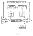
- FIG. 1 illustrates a system for determining Raman gain in a fiber optic span in accordance with an embodiment of the present invention.
- Cost-effective optical spectrum analyzers (OSAs) 110 are provided in order to monitor wavelength power profiles, which permits the mapping of transmit and receive profiles within a fiber optic span 100. If collected at a central location, such as at processor 150, this mapping information may be utilized to derive the Raman gain within the span.
- the processor 150 is located at the receiving end of the span 100.
- the following information is necessary in order to determine the spectral contribution (G3) of Raman pumps 140 incident on the receive amplifier 130: the originating profile (P1) of up-stream transmit amplifier 120; the loss profile (L2) for fiber optic span 100; and the profile (P4) measured at the input to the receive amplifier 130.
- Calculation of G3( ⁇ ) is preferably performed at the receiving end. This calculation may be performed automatically by the processor 150, or by any other means capable of doing so. Alternatively, this calculation may be performed manually. Advantageously, the result of this calculation may be displayed on a display means 160.
- the gain and ripple in the Raman gain profile will both be directly mapped as opposed to being estimated through reliance on model equations.
- the measurement of an actual spectral profile at the receive amplifier 130 by optical spectrum analyzer 110 permits pre-compensation of the Raman gain profile to be implemented and tracked with a high level of confidence.
- a tolerance band may be defined in the transmit amplifier profile P1( ⁇ ), within which minor localized changes in its output gain and ripple would not warrant a complete update of its spectral content information to the receive amplifier 130. Only under changes causing an "event" in the transmit amplifier's output operating profile would a complete profile update be sent.
- An event may be any one of: a profile change outside of the tolerance band, wavelength additions, loss of wavelengths, etc.
- a method may be put in place to convey only basic information across the overhead channel (such as wavelength x has been added with power y). Short term reliance on the open loop Raman amplifier model equations (resident with the Raman circuit pack) would be permitted to make limited independent adjustments to the Raman pumps 140 in order to accommodate transmitted profile changes. Closed loop corrective measures may be implemented when the complete up-stream information can be conveyed across the overhead channel.
- any Raman gain derivation technique that treats the fiber loss profile as a static entity should cause some concern. Under such conditions, any degradation to the passive elements in the system (such as that due to temperature variations) would result in false estimates of the Raman gain. Therefore, whether the fiber loss profile is initially procured through measurement techniques, or estimated based on typical fiber characteristics, this profile information will need to be dynamic, being updated periodically based on receive amplifier OSA measurements.
- Input spectral profile information can be measured at the receive amplifier 130. If this input profile, P4( ⁇ ), changes, but it is known that the booster output profile, P1( ⁇ ), has remained consistent, and output power monitor conditions remain unchanged on the Raman pumps 140 (total power as well as individual pump powers), then the changes can be inferred to have occurred along the transmission medium.
- a desired Raman gain profile can be chosen knowing the following values: the output of the transmit amplifier, P1( ⁇ ); the desired profile at the receive amplifier input, P4( ⁇ ); and an initial condition profile for the span loss, L2( ⁇ ).
- loss profile is assumed to be correct (due to measurement or due to inferred profile based on typical fiber characteristics). This is a necessary starting point.
- a change in the loss profile will be noticed as a change of the profile incident upon the receive amplifier.
- changes in P4( ⁇ ) may be attributed to a change in the loss of the transmission fiber L2( ⁇ ).
- a change in L2( ⁇ ) will result in a change in G3( ⁇ ) through a change in the effective length of the Distributed Raman amplifier.
- the ⁇ L ( ⁇ ) parameter can then be re-estimated by subtracting ⁇ G ( ⁇ ) from the measured value ⁇ ( ⁇ ):
- Updates to the loss profile and Raman Gain profile may be made regularly in incremental iterative steps.
- Figure 2 is a modification of the concepts presented in earlier.
- an extra element 200 with a loss profile of C5 has been added to account for the static passive losses that will appear at the receiving end.
- Two other parameters are considered as well: L2' and P4'.
- the profile P4, at the input of receive amplifier 130, is measured after the static losses, C5.
- the equivalent profile measurement without static losses is P4'.
- L2 Since loss profile measurements, L2, will also be made at the input to the dual amplifier, the loss due to the fiber alone (without C5) is noted in the diagram as L2'.
- Raman gain, G3 needs to be defined as the actual gain derived by pumping the fiber. Hence, when setting up pump powers to deliver fiber gain, one should account for the additional static loss C5 (relatively easy to do with closed loop gain control).
- Measurement of the loss profile can be effected under start of life, non-traffic-carrying conditions. If the transmit amplifier pumps are turned up to deliver superfluous (high power) Amplified Spontaneous Emission (ASE), this launched ASE profile could first be measured at the amplifier output using the OSA, and then measured at the receiving dual amplifier input. The difference between the profiles would be the mapping of the span loss profile.
- ASE Amplified Spontaneous Emission
- the Raman pump power settings need to be calculated relative to the fiber loss profile in order to achieve a specified Raman gain profile. For this reason, the fiber loss profile needs to be measured (or estimated by a typical value).
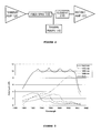
- the combined Raman flat gain profile is the result of the superposition of several individual pump wavelength profiles, as illustrated in Figure 3.
- One solution to this problem is accomplished by measuring the pump profile on-site. Under the same start of life (traffic free) conditions used in determining the loss profile, each pump wavelength can be turned up independently, and the resultant profile mapped at the receive amplifier. The resultant profile is derived through the difference between the ASE profile incident on the receiver amplifier before and after the Raman pump power application. This technique would be particularly valuable in a situation wherein a foreign fiber type has previously been spliced into a span, and the typical profile for the dominant fiber type may not be applicable.
- the Raman gain within a span is to have a value Y
- two other gain values can be measured using the above procedure, X being a value marginally below the desired point, and Z being a value marginally above the desired point.
- the error between the set-point gain X and measured results can be obtained.
- the error between the set-point gain Z and measured results can be obtained. From interpolation between these error results, a linear function on the expected error in the gain Y can be found and used to first provide initial pump offsets on the model, and then for adjustment purposes.
Landscapes
- Physics & Mathematics (AREA)
- Electromagnetism (AREA)
- Engineering & Computer Science (AREA)
- Plasma & Fusion (AREA)
- Optics & Photonics (AREA)
- Optical Modulation, Optical Deflection, Nonlinear Optics, Optical Demodulation, Optical Logic Elements (AREA)
Abstract
Description
- Figure 1
- illustrates diagrammatically a system for determining Raman gain in accordance with an embodiment of the present invention;
- Figure 2
- illustrates diagrammatically a consideration of passive losses at the receiving end of a system according to Figure 1; and
- Figure 3
- illustrates graphically individual pump wavelength profiles as well as a superposition of a single pump Raman gain profile in a system according to Figure 1.


Claims (22)
- A method of determining a Raman gain profile of an optically amplified fiber optic span, said method comprising the steps of:obtaining a first measured power profile for each of a plurality of system components;applying one or more Raman pumps to said fiber optic span for providing additional optical amplification thereto;obtaining a second measured power profile for each of said plurality of system components; andcalculating the Raman gain profile for the system based on the changes in the measured power profiles.
- A method according to Claim 1, wherein power settings for the Raman pump are calculated relative to a loss profile of a fiber optic span measured under non traffic-carrying conditions in order to achieve a specified Raman gain profile.
- A method according to Claim 1 or 2, wherein said step of measuring a power profile for each of a plurality of system components includes measuring: an originating profile at an output of a transmit amplifier, a loss profile of a fiber optic span, and an incident profile at an input of a receive amplifier.
- A method according to Claim 3, wherein if the incident profile changes, and it is known that the originating profile remains unchanged and the output power monitor conditions remain unchanged on the Raman pumps, it may be determined that changes in the measured power profiles have occurred along the fiber optic span.
- A method according to any preceding claim, further comprising the steps of:continually monitoring power profiles of each of said plurality of system components after application of said one or more Raman pumps;transmitting any change in said power profiles to a central location; andrecalculating, in real-time, the Raman gain profile following such change.
- A method according to Claim 5, wherein said step of measuring a power profile for each of a plurality of system components includes measuring an originating profile at an output of a transmit amplifier, a loss profile of a fiber optic span, and an incident profile at an input of a receive amplifier.
- A method according to Claim 5 or 6, wherein the step of transmitting changes in the measured power profiles comprises conveying basic information over an overhead channel.
- A method according to Claim 5, 6 or 7, wherein the step of transmitting changes is performed when the magnitude of the change is outside limits defined by a tolerance band.
- A method according to Claim 1 wherein said step of measuring a power profile for each of a plurality of system components includes measuring: an originating profile at an output of a transmit amplifier, a loss profile of a fiber optic span, and an incident profile at an input of a receive amplifier.
- A method according to Claim 6, wherein the step of transmitting changes comprises conveying a status update on a regular basis from the transmit amplifier.
- A method according to Claim 6 wherein said step of dynamically calculating Raman gain profile comprises summing updated values of the incident profile and the loss profile, and subtracting therefrom the originating profile.
- A method according to Claim 6, wherein said step of dynamically calculating the Raman gain profile is performed at said receive amplifier.
- A system for determining a Raman gain profile of an optically amplified fiber optic span, said system comprising:a plurality of optical spectrum analyzers for measuring first and second power profiles of said fiber optic span and of a plurality of system components, said first power profiles being measured before application of one or more Raman pumps to said fiber optic span, and said second power profiles being measured after application of said one or more Raman pumps, so as to determine the existence of a loss or a gain therein;means for receiving the measured power profiles from the optical spectrum analyzers; andmeans for calculating the Raman gain profile for the system based on the difference in the measured power profiles.
- A system according to Claim 13, further comprising:means for continually monitoring power profiles of each of said plurality of system components after application of said one or more Raman pumps;means for transmitting any change in said power profiles to a central location; andmeans for recalculating in real-time, the Raman gain profile following such change.
- A system according to Claim 13 or 14, further comprising an overhead channel for conveying the changes in the measured power profiles.
- A system according to Claim 13, 14 or 15, further comprising a display means for displaying the result of said calculation.
- A system according to any of Claims 13 to 16, wherein the means for receiving comprises a processor.
- A system according to any of Claims 13 to 17, wherein the means for dynamically calculating comprises a processor.
- A system according to any of Claims 13 to 18, wherein the means for receiving and the means for dynamically calculating are integral with one another.
- A system according to any of Claims 13 to 19, wherein said system components include a transmit amplifier and a receive amplifier.
- A system according to claim 20, wherein said means for receiving and said receive amplifier are integral with one another.
- A system according to claim 19, wherein said means for receiving, said means for dynamically calculating, and said receive amplifier are all integral with one another.
Applications Claiming Priority (2)
| Application Number | Priority Date | Filing Date | Title |
|---|---|---|---|
| US824798 | 2001-04-04 | ||
| US09/824,798 US6734954B2 (en) | 2001-04-04 | 2001-04-04 | Method and system for automatic Raman gain control |
Publications (2)
| Publication Number | Publication Date |
|---|---|
| EP1248334A2 true EP1248334A2 (en) | 2002-10-09 |
| EP1248334A3 EP1248334A3 (en) | 2004-03-10 |
Family
ID=25242340
Family Applications (1)
| Application Number | Title | Priority Date | Filing Date |
|---|---|---|---|
| EP02252399A Withdrawn EP1248334A3 (en) | 2001-04-04 | 2002-04-02 | Methods and system for automatic raman gain control |
Country Status (3)
| Country | Link |
|---|---|
| US (1) | US6734954B2 (en) |
| EP (1) | EP1248334A3 (en) |
| CA (1) | CA2378069A1 (en) |
Cited By (13)
| Publication number | Priority date | Publication date | Assignee | Title |
|---|---|---|---|---|
| US7142356B2 (en) | 2005-02-24 | 2006-11-28 | At&T Corp. | Fast dynamic gain control in an optical fiber amplifier |
| DE102006013777A1 (en) * | 2006-03-24 | 2007-06-28 | Siemens Ag | Transmission function determining method for use in wavelength-division multiplexing system, involves determining efficient transmission from ratio of efficiency value of broad band reference signal and value within broadband of channel |
| US7277221B2 (en) | 2005-11-15 | 2007-10-02 | At&T Corp. | Fast dynamic gain control in cascaded Raman fiber amplifiers |
| US7280269B2 (en) | 2005-11-15 | 2007-10-09 | At&T Corporation | Fast dynamic gain control in cascaded Raman fiber amplifiers |
| US7280270B2 (en) | 2005-11-15 | 2007-10-09 | At&T Corporation | Fast dynamic gain control in cascaded Raman fiber amplifiers |
| US7280271B2 (en) | 2005-11-15 | 2007-10-09 | At&T Corp. | Fast dynamic gain control in cascaded Raman fiber amplifiers |
| US7436582B2 (en) | 2005-11-15 | 2008-10-14 | At&T Corp. | Fast dynamic gain control in a bidirectionally-pumped Raman fiber amplifier |
| US7446932B2 (en) | 2006-06-15 | 2008-11-04 | At&T Corporation | Method, apparatus and system for cost effective optical transmission with fast Raman tilt transient control |
| US7554719B2 (en) | 2005-02-24 | 2009-06-30 | At&T Corporation | Fast dynamic gain control in an optical fiber amplifier |
| US7636192B2 (en) | 2006-06-15 | 2009-12-22 | At&T Corp. | Method, apparatus and system for cost effective optical transmission with fast Raman tilt transient control |
| US7769302B1 (en) | 2007-03-13 | 2010-08-03 | At&T Intellectual Property Ii, L.P. | Method and apparatus for adjusting for polarization-induced, optical signal transients |
| WO2011023220A1 (en) | 2009-08-25 | 2011-03-03 | Nokia Siemens Networks Oy | Method and arrangement for in service raman gain measurement and monitoring |
| US7916384B2 (en) | 2006-05-02 | 2011-03-29 | At&T Intellectual Property Ii, L.P. | Feedback dynamic gain control for a WDM system employing multi wavelength pumped Raman fiber amplifiers |
Families Citing this family (5)
| Publication number | Priority date | Publication date | Assignee | Title |
|---|---|---|---|---|
| EP1630984A1 (en) * | 2004-08-30 | 2006-03-01 | Alcatel | Method for controlling the power of an optical amplifier |
| EP1675283B1 (en) * | 2004-12-23 | 2007-04-18 | Alcatel Lucent | Method of controlling the gain of a raman amplifier |
| US7167299B1 (en) * | 2006-01-31 | 2007-01-23 | Lucent Technologies Inc. | Method and apparatus for controlling pump powers of broadband Raman amplifiers in optical transmission systems incorporating virtual channels to reduce noise |
| US8885248B2 (en) | 2012-10-17 | 2014-11-11 | Ciena Corporation | Raman amplifier gain compression systems and methods based on signal power monitoring |
| US9300110B2 (en) | 2013-09-26 | 2016-03-29 | Cisco Technology, Inc. | Multi-wavelength distributed raman amplification set-up |
Family Cites Families (8)
| Publication number | Priority date | Publication date | Assignee | Title |
|---|---|---|---|---|
| FR2781321A1 (en) * | 1998-07-06 | 2000-01-21 | Alsthom Cge Alcatel | QUASI-DISTRIBUTED AMPLIFICATION IN A SOLITON SIGNAL FIBER OPTIC TRANSMISSION SYSTEM |
| KR100328291B1 (en) * | 1998-07-14 | 2002-08-08 | 노베라 옵틱스 인코포레이티드 | Fiber-optic light source with active amplifier-specific gain and variable output spectrum |
| US6344922B1 (en) * | 1998-07-21 | 2002-02-05 | Corvis Corporation | Optical signal varying devices |
| EP2306604B1 (en) * | 1998-07-23 | 2012-09-05 | The Furukawa Electric Co., Ltd. | Optical repeater comprising a Raman amplifier |
| US6587261B1 (en) * | 1999-05-24 | 2003-07-01 | Corvis Corporation | Optical transmission systems including optical amplifiers and methods of use therein |
| US6697558B2 (en) * | 2000-03-03 | 2004-02-24 | Fitel U.S.A. Corp | Raman amplified optical system with reduction of four-wave mixing effects |
| JP4628523B2 (en) * | 2000-06-13 | 2011-02-09 | 富士通株式会社 | Method, apparatus and system for evaluating characteristics of optical fiber transmission line |
| US6417958B1 (en) * | 2001-01-24 | 2002-07-09 | Lucent Technologies Inc. | WDM optical communication system using co-propagating Raman amplification |
-
2001
- 2001-04-04 US US09/824,798 patent/US6734954B2/en not_active Expired - Fee Related
-
2002
- 2002-03-21 CA CA002378069A patent/CA2378069A1/en not_active Abandoned
- 2002-04-02 EP EP02252399A patent/EP1248334A3/en not_active Withdrawn
Cited By (18)
| Publication number | Priority date | Publication date | Assignee | Title |
|---|---|---|---|---|
| US7554719B2 (en) | 2005-02-24 | 2009-06-30 | At&T Corporation | Fast dynamic gain control in an optical fiber amplifier |
| US7898732B2 (en) | 2005-02-24 | 2011-03-01 | At&T Intellectual Property Ii, L.P. | Fast dynamic gain control in a bidirectionally-pumped Raman fiber amplifier |
| US7672042B2 (en) | 2005-02-24 | 2010-03-02 | At&T Corporation | Fast dynamic gain control in an optical fiber amplifier |
| US7554718B2 (en) | 2005-02-24 | 2009-06-30 | At&T Corporation | Fast dynamic gain control in an optical fiber amplifier |
| US7142356B2 (en) | 2005-02-24 | 2006-11-28 | At&T Corp. | Fast dynamic gain control in an optical fiber amplifier |
| US7280270B2 (en) | 2005-11-15 | 2007-10-09 | At&T Corporation | Fast dynamic gain control in cascaded Raman fiber amplifiers |
| US7436582B2 (en) | 2005-11-15 | 2008-10-14 | At&T Corp. | Fast dynamic gain control in a bidirectionally-pumped Raman fiber amplifier |
| US7280271B2 (en) | 2005-11-15 | 2007-10-09 | At&T Corp. | Fast dynamic gain control in cascaded Raman fiber amplifiers |
| US7280269B2 (en) | 2005-11-15 | 2007-10-09 | At&T Corporation | Fast dynamic gain control in cascaded Raman fiber amplifiers |
| US7277221B2 (en) | 2005-11-15 | 2007-10-02 | At&T Corp. | Fast dynamic gain control in cascaded Raman fiber amplifiers |
| DE102006013777A1 (en) * | 2006-03-24 | 2007-06-28 | Siemens Ag | Transmission function determining method for use in wavelength-division multiplexing system, involves determining efficient transmission from ratio of efficiency value of broad band reference signal and value within broadband of channel |
| US7916384B2 (en) | 2006-05-02 | 2011-03-29 | At&T Intellectual Property Ii, L.P. | Feedback dynamic gain control for a WDM system employing multi wavelength pumped Raman fiber amplifiers |
| US7446932B2 (en) | 2006-06-15 | 2008-11-04 | At&T Corporation | Method, apparatus and system for cost effective optical transmission with fast Raman tilt transient control |
| US7636192B2 (en) | 2006-06-15 | 2009-12-22 | At&T Corp. | Method, apparatus and system for cost effective optical transmission with fast Raman tilt transient control |
| US7995269B2 (en) | 2006-06-15 | 2011-08-09 | At&T Intellectual Property Ii, L.P. | Cost effective optical transmission with fast raman tilt transient control |
| US7769302B1 (en) | 2007-03-13 | 2010-08-03 | At&T Intellectual Property Ii, L.P. | Method and apparatus for adjusting for polarization-induced, optical signal transients |
| WO2011023220A1 (en) | 2009-08-25 | 2011-03-03 | Nokia Siemens Networks Oy | Method and arrangement for in service raman gain measurement and monitoring |
| US8768165B2 (en) | 2009-08-25 | 2014-07-01 | Xieon Networks S.A.R.L. | Method and arrangement for in service Raman gain measurement and monitoring |
Also Published As
| Publication number | Publication date |
|---|---|
| EP1248334A3 (en) | 2004-03-10 |
| US6734954B2 (en) | 2004-05-11 |
| US20020163635A1 (en) | 2002-11-07 |
| CA2378069A1 (en) | 2002-10-04 |
Similar Documents
| Publication | Publication Date | Title |
|---|---|---|
| US6734954B2 (en) | Method and system for automatic Raman gain control | |
| US7835067B2 (en) | Raman amplifier | |
| US8643941B2 (en) | Automatic measurement and gain control of distributed Raman amplifiers | |
| EP2993806A1 (en) | Live monitoring of raman and fiber degradation in dwdm networks using in-service otdr | |
| US20020041429A1 (en) | Optical amplification apparatus utilizing raman amplification and controlling method thereof | |
| EP2880790B1 (en) | Method of optimizing optical signal quality in an optical communications link, optical network element and optical communications link | |
| EP3050229B1 (en) | Multi-wavelength distributed raman amplification set-up | |
| US20100226661A1 (en) | Wavelength division multiplexing transmission system and apparatus and optical signal noise ratio calculation method | |
| EP2345116B1 (en) | Optical network amplifier node and method of channel power depletion compensation | |
| US20070217794A1 (en) | Method for measuring optical characteristics and system thereof | |
| JP4478489B2 (en) | Raman optical amplifier and method for adjusting Raman optical amplifier | |
| US6452715B1 (en) | Method and apparatus for determining a fiber plant gain transfer function and utilizing same to control distributed gain | |
| JP2017017605A (en) | Transmission path loss measuring apparatus, transmission path loss measuring method, and optical transmission system | |
| US6985284B2 (en) | Method, apparatus and system for controlling power transients in a Raman-amplified optical transmission system | |
| EP1467506B1 (en) | Method, apparatus and system for controlling the effects of power transients in optical transmission systems | |
| JP3878641B2 (en) | Optical transmission system with noise light correction function by Raman amplification | |
| JP5104357B2 (en) | Raman amplification apparatus, distributed Raman amplification system, and startup method thereof | |
| US8768165B2 (en) | Method and arrangement for in service Raman gain measurement and monitoring | |
| US20040042068A1 (en) | Apparatus and method for Raman gain spectral control | |
| US7379234B2 (en) | Quality monitoring of an optical fiber amplifier | |
| US6519066B2 (en) | System level stimulated raman scattering (SRS) compensation | |
| CN101331696B (en) | Method and device for compensating channel loss of multi-channel signal in optical link or optical network | |
| RU2695775C1 (en) | Method of measuring margin by osnr in communication line with spectral multiplexing dwdm and encoding signal with fec error correction |
Legal Events
| Date | Code | Title | Description |
|---|---|---|---|
| PUAI | Public reference made under article 153(3) epc to a published international application that has entered the european phase |
Free format text: ORIGINAL CODE: 0009012 |
|
| AK | Designated contracting states |
Kind code of ref document: A2 Designated state(s): AT BE CH CY DE DK ES FI FR GB GR IE IT LI LU MC NL PT SE TR |
|
| AX | Request for extension of the european patent |
Free format text: AL;LT;LV;MK;RO;SI |
|
| PUAL | Search report despatched |
Free format text: ORIGINAL CODE: 0009013 |
|
| AK | Designated contracting states |
Kind code of ref document: A3 Designated state(s): AT BE CH CY DE DK ES FI FR GB GR IE IT LI LU MC NL PT SE TR |
|
| AX | Request for extension of the european patent |
Extension state: AL LT LV MK RO SI |
|
| RIC1 | Information provided on ipc code assigned before grant |
Ipc: 7H 01S 3/067 B Ipc: 7H 01S 3/30 B Ipc: 7H 04B 10/17 A |
|
| 17P | Request for examination filed |
Effective date: 20040810 |
|
| AKX | Designation fees paid |
Designated state(s): DE FR GB |
|
| STAA | Information on the status of an ep patent application or granted ep patent |
Free format text: STATUS: THE APPLICATION IS DEEMED TO BE WITHDRAWN |
|
| 18D | Application deemed to be withdrawn |
Effective date: 20061101 |