EP1248147A1 - A method and system for photographic processing - Google Patents
A method and system for photographic processing Download PDFInfo
- Publication number
- EP1248147A1 EP1248147A1 EP20020006858 EP02006858A EP1248147A1 EP 1248147 A1 EP1248147 A1 EP 1248147A1 EP 20020006858 EP20020006858 EP 20020006858 EP 02006858 A EP02006858 A EP 02006858A EP 1248147 A1 EP1248147 A1 EP 1248147A1
- Authority
- EP
- European Patent Office
- Prior art keywords
- processing
- storage device
- stage
- photographic material
- processing stage
- Prior art date
- Legal status (The legal status is an assumption and is not a legal conclusion. Google has not performed a legal analysis and makes no representation as to the accuracy of the status listed.)
- Withdrawn
Links
- 238000012545 processing Methods 0.000 title claims abstract description 145
- 238000000034 method Methods 0.000 title claims abstract description 23
- 239000000463 material Substances 0.000 claims abstract description 54
- 238000001035 drying Methods 0.000 claims description 26
- 238000004061 bleaching Methods 0.000 claims description 8
- 238000005406 washing Methods 0.000 claims description 7
- 238000004590 computer program Methods 0.000 claims 1
- 239000012530 fluid Substances 0.000 claims 1
- 238000012993 chemical processing Methods 0.000 description 6
- 239000002918 waste heat Substances 0.000 description 5
- 238000003491 array Methods 0.000 description 4
- 238000010586 diagram Methods 0.000 description 4
- -1 silver halide Chemical class 0.000 description 2
- 239000007795 chemical reaction product Substances 0.000 description 1
- 238000004891 communication Methods 0.000 description 1
- 238000007796 conventional method Methods 0.000 description 1
- 230000000994 depressogenic effect Effects 0.000 description 1
- 230000000694 effects Effects 0.000 description 1
- 238000009790 rate-determining step (RDS) Methods 0.000 description 1
- 229910052709 silver Inorganic materials 0.000 description 1
- 239000004332 silver Substances 0.000 description 1
Images


Classifications
-
- G—PHYSICS
- G03—PHOTOGRAPHY; CINEMATOGRAPHY; ANALOGOUS TECHNIQUES USING WAVES OTHER THAN OPTICAL WAVES; ELECTROGRAPHY; HOLOGRAPHY
- G03D—APPARATUS FOR PROCESSING EXPOSED PHOTOGRAPHIC MATERIALS; ACCESSORIES THEREFOR
- G03D3/00—Liquid processing apparatus involving immersion; Washing apparatus involving immersion
- G03D3/08—Liquid processing apparatus involving immersion; Washing apparatus involving immersion having progressive mechanical movement of exposed material
- G03D3/13—Liquid processing apparatus involving immersion; Washing apparatus involving immersion having progressive mechanical movement of exposed material for long films or prints in the shape of strips, e.g. fed by roller assembly
- G03D3/132—Liquid processing apparatus involving immersion; Washing apparatus involving immersion having progressive mechanical movement of exposed material for long films or prints in the shape of strips, e.g. fed by roller assembly fed by roller assembly
Definitions
- the present invention relates to a method and system for photographic processing.
- the invention is particularly suitable for use in single chamber processing systems such as, for example, the system disclosed in United Kingdom Patent Application Number 0023091.2 in the name of The Eastman Kodak Company.
- a number of distinct stages are involved such as, for example, developing, fixing/bleaching and washing stages.
- the film passes sequentially through each of these stages to produce the negatives, which are used to prepare developed photographs or scanned images.
- all of the stages take place sequentially in a common chamber.
- the film After the washing stage the film is usually dried before, as a final step of the processing, it is scanned or used together with photographic paper to produce an end product.
- the rate at which film can be processed is determined by the rate at which access to the chemical processing chamber (or chambers) of the processing system can be achieved. In a batch type process the time taken to remove film from the chemical processing chamber determines the overall utilisation of the system. Where the "rate determining step" for the process is external to the processing chamber, such as a low end type scanner, or slow dryer, it is only once the film has passed these stages that the processing chamber may become available to accept subsequent films.
- a photographic processing system comprising:
- the first processing stage comprises one or more of developing, fixing, bleaching, combined fixing/bleaching and washing.
- the photographic material may be film, in which case the second processing stage may comprise scanning the developed film.
- the storage facility comprises a wet slack box having one or more path defining means such as rollers to define a storage path for photographic material that is output from the processing stage prior to entry into the scanning stage.
- path defining means such as rollers to define a storage path for photographic material that is output from the processing stage prior to entry into the scanning stage.
- Any other suitable sort of device may be used to define a path for the photographic material in the storage device such as, for example, an air knife.
- the path defining means are moveable with respect to the webbing (and each other when there is more than one) to vary the length of the storage path.
- the storage device also performs a drying function.
- the storage device may be used as a final wash stage.
- a photographic processing system comprising:
- the heat provided from the processing system is exhaust heat from the drying stage.
- the present invention provides a system in which the photographic material is able to exit the processing stage of the system at a different rate from that at which it enters the scanning stages. This effectively separates the scanning stage from the processing stage and enables the processing chamber(s) to be emptied before the scanning of the previous film. If the processing chamber is emptied, processing of the next film in sequence can start earlier than would otherwise have been possible thereby reducing the overall cycle time taken to process the films. This is particularly relevant to a single chamber batch processing system.
- rollers in a wet slack box provide a mechanically simple and robust system which enable photographic material to be stored safely prior to entering the scanner of the photographic system.
- the rollers are moveable relative to each other the path length of photographic material stored in the slack box is variable enabling the amount of material stored to be controlled as desired in any particular situation.
- the drying time of the material in the scanner can be greatly reduced. This means that the path length can be reduced of the material, which enables the overall system footprint to be correspondingly reduced.
- a detector is provided to detect a parameter of the film stored in the storage device and provide a corresponding signal to the dryer.
- This parameter may be, for example, the humidity of the air in the storage device, which is related to the level of moisture contained in the stored film.
- FIG. 1 shows a schematic block diagram of an example of a photographic processing system according to the present invention.
- the system will be described with reference to a film processing system although it relates equally to other photographic material such as silver halide photographic paper.
- the system has one or more chemical processing chambers 2 to receive and process photographic material such as film.
- a conventional photographic processing system such as a mini-lab, separate chambers are provided for each of developing, fixing/bleaching and washing.
- the single chamber processor described in UK Patent Application number 0023091.2 all the steps of the processing are performed sequentially in a common chamber.
- the following description is written with reference to a single chamber processor as described in UK Patent Application number 0023091.2 although the invention also applies to conventional photographic processing systems.
- the film is provided to the film-processing chamber 2 of the processor.
- the necessary steps in chemical processing are carried out sequentially on the film as in conventional photographic processing.
- the film exits the chemical processing chamber it proceeds to the drying and scanning chamber 6 and if necessary can be stored in the storage device 4.
- the storage device 4 enables the film to be removed completely from the processing chamber 2 as soon as the processing is complete, thereby enabling the processing chamber to receive a second film to be processed without delay.
- Figures 2a to 2d show a first example of a storage device suitable for use in the processing system of Figure 1, in various stages of operation.
- the storage device has first and second roller pairs 8 and 10 arranged to receive the photographic material (film) after it has been processed in the chamber 2.
- the rollers 8 and 10 are moved apart from each other as shown in Figure 2b.
- a third roller 12 shown in Figure 2c is brought to bear on the film between the rollers 8 and 10 thereby increasing the path length between them.
- Figure 2d shows roller 12 in its fully depressed condition at which point the path length of the film between rollers 8 and 10 is at a maximum.
- the film In the case of a single chamber processor, the film will be fully fixed and washed once it exits from the processing chamber. There is therefore no need for the storage device 4 to be light-tight. However, if the device is to be used to store film that has not yet been fixed, a light-tight arrangement will be required.
- rollers 8 and 10 may be replaced by an array of spaced rollers and that roller 12 could be replaced by a moveable array of correspondingly spaced rollers.
- the change in path length will be much greater.
- Figures 6 shows an example of a suitable arrangement of rollers that could be used.
- the two arrays of rollers must be moveable relative to each other.
- Any other suitable device may be used to control the path length of the film in the storage device 4.
- one or more air knives may be used instead of rollers.
- FIG 3 shows a second example of a storage device suitable for use in the processing system of Figure 1.
- the principle of operation of the storage device is the same as that described above with reference to Figures 2a to 2d.
- the storage device also operates as a wash stage so that one less processing step needs to take place in the main processing chamber 2 (from figure 1 above).
- a chamber 14 is therefore provided to hold a wash solution which washes the film as roller 12 is moved in a downward direction, away from rollers 8 and 10.
- Tables 1 and 2 below show timing plans respectively for a processor as described in UK Patent application number 0023091.2 and a photographic processing system according to the present invention.
- Time(s) Film 1 Film 2 Film 3 0 Into processor 300 Out of processor and into scanner/dryer 1100 Scanning complete Into processor 1400 Out of processor and into scanner/dryer 2200 Scanning complete Into processor 2500 Out of processor and into scanner/dryer 3300 Scanning complete Time(s) Film 1 Film 2 Film 3 0 Into processor 300 Out of processor and into scanner/dryer (via storage device) Into processor 600 Processing complete - into storage device Into processor 900 Processing complete - into storage device 1100 Scanning complete Out of storage device and into scanner/dryer 1900 Scanning complete Out of storage device and into scanner/dryer 2700 Scanning complete
- the time taken to process each of the films is 300 seconds(s) and the time taken to dry and scan each of the films is 800s.
- Table 2 shows the steps in processing three films identical to the ones used in Table 1 above, using a processing system according to the present invention. Again, for the sake of example, it is assumed that the time taken to process each of the films is 300 seconds(s) and the time taken to dry and scan each film is 800s.
- the first film enters the processor.
- the processing chamber is therefore empty again and can now receive the third and final film in the batch.
- a time saving of approximately 600s (18%) has been achieved. This is clearly a considerable improvement.
- FIG 4 shows a schematic block diagram of a further example of a photographic processing system according to the present invention.
- the processing system has the same components as in Figure 1 described above but in this case is also provided with a drying control system 16.
- the drying control system has a sensor 18, such as a temperature and/or humidity sensor, in communication with the storage device 4.
- the sensor 18 must be capable of detecting a parameter of the film such that the drying can be controlled in dependence thereon.
- the parameter may be the temperature or humidity of air in the storage device.
- a feedback control unit 20 is coupled between the sensor 18 and a heater/motor device 22 associated with the dryer 6.
- a waste heat coupler 24 is also provided to couple waste heat from the dryer to the storage device 4.
- the waste heat coupler may be a hot-air duct to channel exhaust air from the dryer to the storage device 6. Any other suitable form of heat coupler could be used so long as it is capable of transferring excess heat from the dryer 6 to the storage device 4. Exhaust or waste heat may also be transferred to the storage device form any other suitable source, such as a different part of the processing system.
- the heater/motor device 22 is arranged to provide heat to the dryer 6 controlled in dependence on a signal received from the feedback control unit 20.
- the temperature and the humidity of the storage device will rise and fall respectively. This means that an amount of drying of the film is actually performed in the storage device 4. This is detected by the sensor 18, which sends a corresponding signal to the feedback control unit 20 to adjust the heat provided to the dryer 6.
- the rate at which film passes through the drier may be controlled accordingly. For example, if it is detected that film in the storage device 4 is substantially dry, the rate at which the film passes through the dryer 6 can be increased.
- the path length though the dryer 6 can be reduced so that the dryer may be made smaller thereby reducing the footprint of the processing system.
- the control provided by the feedback control unit 20 may be achieved using an associated microprocessor or a computer set up to run an appropriate control program.
- a digital signal processor DSP
- the signal obtained from the sensor 18 is converted to a digital signal by an analogue-to-digital converter and the digital signal is then provided to the DSP.
- the DSP may then function to obtain a set point from a look up table and generate an appropriate output to the heater to control the temperature of the dryer.
- Use of a DSP enables accurate control of the dryer temperature to be achieved
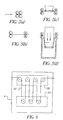
- FIG 5 shows an example of a storage device suitable for use in the processing system of Figure 4.
- the storage device has essentially the same components as the one shown in Figures 2a to 2d.
- the roller 12 from Figures 2a to 2d is replaced with a dryer 26.
- the dryer 26 is arranged to provide warm air received from the air duct 24 shown in Figure 4.
- Figure 6 shows an alternative arrangement for the storage device 4 for use in the processing system of the present invention.
- two arrays 28 and 30 of rollers are provided to define a storage path of variable length for the photographic material 32 in the storage device.
- the two arrays it is necessary for the two arrays to be moveable with respect to each other to enable the length of the storage path to be varied. It is possible that the array 28 is fixed and the array 30 is moved in a downward direction or that the array 30 is fixed and that the array 28 is moved in an upward direction.
- any suitable item may be used to define the storage path for the photographic material such as, for example, air knives.
Landscapes
- Physics & Mathematics (AREA)
- General Physics & Mathematics (AREA)
- Photographic Processing Devices Using Wet Methods (AREA)
- Projection-Type Copiers In General (AREA)
Abstract
The invention provides a photographic processing system, having a first
processing stage (2) to process photographic material. A second processing stage
(6) is also provided to further process the photographic material. A storage device
(4) is provided between the first processing stage (2) and the second processing
stage (6) to receive and store photographic material output from the first
processing stage (2) prior to output to the second processing stage (6). This
enables the photographic material to be output from the first processing stage (2)
at a different rate than that at which it is input to the second processing stage (6).
Accordingly, the first processing stage (2) can be vacated for use by subsequent
photographic material before processing in the second processing stage (6) is
complete.
Description
- The present invention relates to a method and system for photographic processing. The invention is particularly suitable for use in single chamber processing systems such as, for example, the system disclosed in United Kingdom Patent Application Number 0023091.2 in the name of The Eastman Kodak Company.
- In conventional methods for processing photographic material, such as film, a number of distinct stages are involved such as, for example, developing, fixing/bleaching and washing stages. In a multi-chamber processing system, the film passes sequentially through each of these stages to produce the negatives, which are used to prepare developed photographs or scanned images. In a single-chamber system, all of the stages take place sequentially in a common chamber.
- After the washing stage the film is usually dried before, as a final step of the processing, it is scanned or used together with photographic paper to produce an end product. The rate at which film can be processed is determined by the rate at which access to the chemical processing chamber (or chambers) of the processing system can be achieved. In a batch type process the time taken to remove film from the chemical processing chamber determines the overall utilisation of the system. Where the "rate determining step" for the process is external to the processing chamber, such as a low end type scanner, or slow dryer, it is only once the film has passed these stages that the processing chamber may become available to accept subsequent films.
- For example, if scanning takes 20 seconds per frame (exposure) of the film then for a 40-exposure film the scanning stage alone takes 800 seconds. It is only once a film has substantially passed through the scanning stage that the next film to be processed can be provided to the processing chamber (or chambers) of the processing system. This problem is particularly noticeable in batch processing in a single chamber processor.
- A problem exists in that during the processing of photographic material, the rate at which certain stages occur, such as scanning and printing, increases the time necessary to process a batch of two or more films. This is because it is not possible to start the processing of a second film when a first film is still present in the processing chamber or chambers. Clearly there is a need for a system that enables this problem to be overcome and in particular enables faster access to the chemical processing chamber or chambers of a photographic processing system.
- According to a first aspect of the present invention, there is provided a photographic processing system, comprising:
- a first processing stage to process photographic material;
- a second processing stage to further process the photographic material; and,
- a storage device provided between the first processing stage and the second processing stage to receive and store photographic material output from the first processing stage prior to output to the second processing stage, to thereby enable said photographic material to be output from the first processing stage at a different rate than that at which it is input to the second processing stage.
-
- Preferably, the first processing stage comprises one or more of developing, fixing, bleaching, combined fixing/bleaching and washing. The photographic material may be film, in which case the second processing stage may comprise scanning the developed film.
- Preferably, the storage facility comprises a wet slack box having one or more path defining means such as rollers to define a storage path for photographic material that is output from the processing stage prior to entry into the scanning stage. Any other suitable sort of device may be used to define a path for the photographic material in the storage device such as, for example, an air knife. Preferably, the path defining means are moveable with respect to the webbing (and each other when there is more than one) to vary the length of the storage path.
- In one preferred example of the present invention, the storage device also performs a drying function. In an alternative example, the storage device may be used as a final wash stage.
- According to a second aspect of the present invention, there is provided a method of processing photographic material comprising the steps of:
- processing the photographic material in a first processing stage;
- storing the processed photographic material output from said first processing stage in a storage device, the storage device being adapted to receive and store a variable amount of said processed photographic material; and,
- providing the stored photographic material to a second processing stage after a predetermined time interval.
-
- According to a third aspect of the present invention, there is provided a photographic processing system, comprising:
- a processing stage to process photographic material;
- a drying stage to dry the photographic material after it has been processed by said processing stage;
- a storage device provided between the processing stage and the drying stage to receive and store said photographic material output from the processing stage to enable said material to be output from the processing stage at a different rate than that at which it is input to the drying stage, wherein heat from the processing system is provided to the storage device to at least partly dry the photographic material therein; and,
- a detector to detect a parameter of the photographic material in the storage device and control the drying stage in dependence thereon.
-
- Preferably, the heat provided from the processing system is exhaust heat from the drying stage.
- The present invention provides a system in which the photographic material is able to exit the processing stage of the system at a different rate from that at which it enters the scanning stages. This effectively separates the scanning stage from the processing stage and enables the processing chamber(s) to be emptied before the scanning of the previous film. If the processing chamber is emptied, processing of the next film in sequence can start earlier than would otherwise have been possible thereby reducing the overall cycle time taken to process the films. This is particularly relevant to a single chamber batch processing system.
- The use of rollers in a wet slack box provide a mechanically simple and robust system which enable photographic material to be stored safely prior to entering the scanner of the photographic system. In addition, where the rollers are moveable relative to each other the path length of photographic material stored in the slack box is variable enabling the amount of material stored to be controlled as desired in any particular situation.
- By providing drying function to the storage device, the drying time of the material in the scanner can be greatly reduced. This means that the path length can be reduced of the material, which enables the overall system footprint to be correspondingly reduced.
- When the storage device is used as a final wash stage it is possible to achieve faster access to the processing chamber.
- In the third aspect of the present invention, a detector is provided to detect a parameter of the film stored in the storage device and provide a corresponding signal to the dryer. This parameter may be, for example, the humidity of the air in the storage device, which is related to the level of moisture contained in the stored film. Once this is known, the temperature in the dryer or the speed of passage of film through the dryer can be changed accordingly to improve the dryer efficiency.
- Examples of the present invention will now be described in detail with reference to the accompanying drawings, in which:
- Figure 1 shows a schematic block diagram of an example of a photographic processing system according to the present invention;
- Figure 2 shows a first example of a storage device suitable for use in the processing system of Figure 1;
- Figure 3 shows a second example of a storage device suitable for use in the processing system of Figure 1;
- Figure 4 shows a schematic block diagram of a further example of a photographic processing system according to the present invention;
- Figure 5 shows an example of a storage device suitable for use in the processing system of Figure 4; and,
- Figures 6 shows an example of an arrangement of rollers suitable for use in a storage device for use in the processing system according to the present invention.
-
- Figure 1 shows a schematic block diagram of an example of a photographic processing system according to the present invention. The system will be described with reference to a film processing system although it relates equally to other photographic material such as silver halide photographic paper. The system has one or more
chemical processing chambers 2 to receive and process photographic material such as film. In a conventional photographic processing system such as a mini-lab, separate chambers are provided for each of developing, fixing/bleaching and washing. In the single chamber processor described in UK Patent Application number 0023091.2 all the steps of the processing are performed sequentially in a common chamber. The following description is written with reference to a single chamber processor as described in UK Patent Application number 0023091.2 although the invention also applies to conventional photographic processing systems. - Initially, the film is provided to the film-
processing chamber 2 of the processor. The necessary steps in chemical processing (developing, fixing/bleaching and washing) are carried out sequentially on the film as in conventional photographic processing. After the film exits the chemical processing chamber it proceeds to the drying andscanning chamber 6 and if necessary can be stored in thestorage device 4. As will be explained below, thestorage device 4 enables the film to be removed completely from theprocessing chamber 2 as soon as the processing is complete, thereby enabling the processing chamber to receive a second film to be processed without delay. - Figures 2a to 2d show a first example of a storage device suitable for use in the processing system of Figure 1, in various stages of operation. The storage device has first and second roller pairs 8 and 10 arranged to receive the photographic material (film) after it has been processed in the
chamber 2. As the film exits from thechamber 2, therollers third roller 12 shown in Figure 2c is brought to bear on the film between therollers roller 12 in its fully depressed condition at which point the path length of the film betweenrollers - In the case of a single chamber processor, the film will be fully fixed and washed once it exits from the processing chamber. There is therefore no need for the
storage device 4 to be light-tight. However, if the device is to be used to store film that has not yet been fixed, a light-tight arrangement will be required. - Although the example shown in Figures 2a to 2d has a single pair of
rollers single roller 12 used to control the path length of the film, it will be appreciated thatrollers roller 12 could be replaced by a moveable array of correspondingly spaced rollers. Thus, when the arrays are brought to bear on each other the change in path length will be much greater. - Figures 6 shows an example of a suitable arrangement of rollers that could be used. Of course it is clear that what is essential is that the two arrays of rollers must be moveable relative to each other. Any other suitable device may be used to control the path length of the film in the
storage device 4. For example, one or more air knives may be used instead of rollers. - Figure 3 shows a second example of a storage device suitable for use in the processing system of Figure 1. In this case, the principle of operation of the storage device is the same as that described above with reference to Figures 2a to 2d. However, in this case the storage device also operates as a wash stage so that one less processing step needs to take place in the main processing chamber 2 (from figure 1 above). A
chamber 14 is therefore provided to hold a wash solution which washes the film asroller 12 is moved in a downward direction, away fromrollers - Tables 1 and 2 below show timing plans respectively for a processor as described in UK Patent application number 0023091.2 and a photographic processing system according to the present invention.
Time(s) Film 1 Film 2Film 3 0 Into processor 300 Out of processor and into scanner/dryer 1100 Scanning complete Into processor 1400 Out of processor and into scanner/dryer 2200 Scanning complete Into processor 2500 Out of processor and into scanner/dryer 3300 Scanning complete Time(s) Film 1 Film 2Film 3 0 Into processor 300 Out of processor and into scanner/dryer (via storage device) Into processor 600 Processing complete - into storage device Into processor 900 Processing complete - into storage device 1100 Scanning complete Out of storage device and into scanner/dryer 1900 Scanning complete Out of storage device and into scanner/dryer 2700 Scanning complete - Referring to Table 1, for the sake of example, it is assumed that the time taken to process each of the films is 300 seconds(s) and the time taken to dry and scan each of the films is 800s. When T=0s, the first film enters the processing chamber. At T=300s the processing is complete and the first film can proceed to the drying and scanning stage. This takes 800s and so at T=1100s the first film has been completely scanned and dried. It is not until substantially all of the 800s has elapsed that the final frame of the first film exits from the processing chamber such that the processing chamber is able to receive the second film. However, once this has happened, the process starts again and so a further 1100s is required to process, dry and scan the second film (and the third film as well). The total time taken to process, dry and scan the three films is therefore approximately 3300s.
- Table 2 shows the steps in processing three films identical to the ones used in Table 1 above, using a processing system according to the present invention. Again, for the sake of example, it is assumed that the time taken to process each of the films is 300 seconds(s) and the time taken to dry and scan each film is 800s. At T=0s, the first film enters the processor. At T=300s, the processing is complete and the first film can be removed from the processing chamber to the storage device from where it is fed to the drying and scanning stage. Since, at T=300s the film can be completely removed from the processing chamber and stored in the storage device, the second film can be fed into the processing chamber without delay. At T=600s the processing of the second film will be complete but the scanning of the first film will not yet have finished. The second film is therefore fed into the storage device where it is stored whilst the scanning of the first film is finished.
- The processing chamber is therefore empty again and can now receive the third and final film in the batch. At T=900s the processing of the third film is completed and it can now be transferred for storage to the
storage device 4. Once the scanning of the first film is complete as T=1100s, the second film can enter the scanner. Scanning and drying of the second film will take the whole 800s and so at T=1900s the third film can enter the scanner and dryer from thestorage device 4. Scanning and drying of the third film will also take the whole 800s and so at T=2700s the processing and scanning of the batch of three films is complete. Thus in comparison to the processor used in the example described with reference to Table 1, a time saving of approximately 600s (18%) has been achieved. This is clearly a considerable improvement. Once the storage device is full to capacity, film will not be able to leave the processing chamber and enter the storage device until a corresponding amount of film has passed from the storage device to the scanning stage. - Figure 4 shows a schematic block diagram of a further example of a photographic processing system according to the present invention. The processing system has the same components as in Figure 1 described above but in this case is also provided with a drying
control system 16. The drying control system has asensor 18, such as a temperature and/or humidity sensor, in communication with thestorage device 4. Thesensor 18 must be capable of detecting a parameter of the film such that the drying can be controlled in dependence thereon. For example, the parameter may be the temperature or humidity of air in the storage device. Afeedback control unit 20 is coupled between thesensor 18 and a heater/motor device 22 associated with thedryer 6. Awaste heat coupler 24 is also provided to couple waste heat from the dryer to thestorage device 4. The waste heat coupler may be a hot-air duct to channel exhaust air from the dryer to thestorage device 6. Any other suitable form of heat coupler could be used so long as it is capable of transferring excess heat from thedryer 6 to thestorage device 4. Exhaust or waste heat may also be transferred to the storage device form any other suitable source, such as a different part of the processing system. - In operation, the heater/
motor device 22 is arranged to provide heat to thedryer 6 controlled in dependence on a signal received from thefeedback control unit 20. As waste heat is coupled to thestorage device 4 via thecoupler 24, the temperature and the humidity of the storage device will rise and fall respectively. This means that an amount of drying of the film is actually performed in thestorage device 4. This is detected by thesensor 18, which sends a corresponding signal to thefeedback control unit 20 to adjust the heat provided to thedryer 6. Alternatively or in addition, the rate at which film passes through the drier may be controlled accordingly. For example, if it is detected that film in thestorage device 4 is substantially dry, the rate at which the film passes through thedryer 6 can be increased. In other words, the greater the amount of drying performed in thestorage device 4, the less required in thedryer 6 so that the temperature of the dryer can be reduced or the time it takes for a particular film to be dried can be correspondingly reduced. In both of these situations, an energy saving is made. In addition, since some drying is performed in thestorage device 4, the path length though thedryer 6 can be reduced so that the dryer may be made smaller thereby reducing the footprint of the processing system. - The control provided by the
feedback control unit 20 may be achieved using an associated microprocessor or a computer set up to run an appropriate control program. Alternatively a digital signal processor (DSP) may be used. In this case, the signal obtained from thesensor 18 is converted to a digital signal by an analogue-to-digital converter and the digital signal is then provided to the DSP. The DSP may then function to obtain a set point from a look up table and generate an appropriate output to the heater to control the temperature of the dryer. Use of a DSP enables accurate control of the dryer temperature to be achieved - Figure 5 shows an example of a storage device suitable for use in the processing system of Figure 4. The storage device has essentially the same components as the one shown in Figures 2a to 2d. However, in this case the
roller 12 from Figures 2a to 2d is replaced with a dryer 26. The dryer 26 is arranged to provide warm air received from theair duct 24 shown in Figure 4. As with theroller 12 in Figures 2 and 3, as the dryer 26 is lowered, it is brought to bear on the film between therollers - Figure 6 shows an alternative arrangement for the
storage device 4 for use in the processing system of the present invention. In this case twoarrays photographic material 32 in the storage device. As mentioned above it is necessary for the two arrays to be moveable with respect to each other to enable the length of the storage path to be varied. It is possible that thearray 28 is fixed and thearray 30 is moved in a downward direction or that thearray 30 is fixed and that thearray 28 is moved in an upward direction. Again, any suitable item may be used to define the storage path for the photographic material such as, for example, air knives.
Claims (20)
- A photographic processing system, comprising:a first processing stage to process photographic material;a second processing stage to further process the photographic material; and,a storage device provided between the first processing stage and the second processing stage to receive and store photographic material output from the first processing stage prior to output to the second processing stage, to thereby enable said photographic material to be output from the first processing stage at a different rate than that at which it is input to the second processing stage.
- A system according to claim 1, in which the system is a single chamber processing system in which the first processing stage comprises developing, fixing, bleaching and washing.
- A system according to claim 1, in which the first processing stage comprises one or more of developing, fixing, bleaching, combined fixing/bleaching and washing.
- A processing system according to any preceding claim, in which the storage device also performs a drying function.
- A system according to any of claims 1 to 4, in which the photographic material is film and the second processing stage comprises scanning developed film.
- A processing system according to claim 5, in which the scanning stage further comprises a dryer and in which a coupler is provided to couple exhaust heat from the dryer to the storage device to enable the storage device to perform the drying function.
- A processing system according to claim 6, further comprising a sensor adapted to detect a parameter of the storage device and provide a corresponding signal to a controller to make a corresponding adjustment to the dryer.
- A processing system according to claim 7, in which the parameter is the temperature of the storage device.
- A processing system according to claim 7, in which the parameter is the humidity of the storage device.
- A processing system according to any preceding claim, in which the storage device comprises a wet slack box having one or more path defining means to define a variable storage path for said photographic material that is output from the first processing stage prior to entry into the second processing stage.
- A processing system according to claim 10, in which the path defining means are rollers.
- A processing system according to claim 10, in which the path defining means are air knives.
- A processing system according to any of claims 7 to 9, in which the controller is a microprocessor adapted to receive a signal from the sensor and provide a control signal to the heater of the dryer to adjust the heat provided to the dryer accordingly.
- A processing system according to claim 13, in which the microprocessor comprises a digital signal processor.
- A processing system according to claim 1, in which the storage device comprises a receptacle to hold a volume of wash fluid, the storage device functioning to wash the material stored therein.
- A method of photographic processing using a system according to any preceding claim.
- A method of photographic processing comprising the steps of:processing photographic material in a first processing stage;storing the photographic material output from said first processing stage in a storage device, the storage device being adapted to receive and store a variable amount of said photographic material; and,providing the stored photographic material to a second processing stage after a predetermined time interval.
- A computer program comprising program code means for controlling all the steps of any of claims 15 or 16 when said program is run on a computer.
- A photographic processing system, comprising:a processing stage to process photographic material;a drying stage to dry the photographic material after it has been processed by said processing stage;a storage device provided between the processing stage and the drying stage to receive and store photographic material output from the processing stage to enable said photographic material to be output from the processing stage at a different rate than that at which it is input to the drying stage, wherein heat from the processing system is provided to the storage device to at least partly dry the photographic material therein; and,a detector to detect a parameter related to the photographic material in the storage device and control the drying stage in dependence thereon.
- A system according to claim 19, in which the heat provided from the processing system is exhaust heat from the drying stage.
Applications Claiming Priority (2)
| Application Number | Priority Date | Filing Date | Title |
|---|---|---|---|
| GB0108388 | 2001-04-04 | ||
| GBGB0108388.0A GB0108388D0 (en) | 2001-04-04 | 2001-04-04 | A method and system for photographic processing |
Publications (1)
| Publication Number | Publication Date |
|---|---|
| EP1248147A1 true EP1248147A1 (en) | 2002-10-09 |
Family
ID=9912198
Family Applications (1)
| Application Number | Title | Priority Date | Filing Date |
|---|---|---|---|
| EP20020006858 Withdrawn EP1248147A1 (en) | 2001-04-04 | 2002-03-26 | A method and system for photographic processing |
Country Status (4)
| Country | Link |
|---|---|
| US (1) | US6572286B2 (en) |
| EP (1) | EP1248147A1 (en) |
| JP (1) | JP2002311511A (en) |
| GB (1) | GB0108388D0 (en) |
Citations (2)
| Publication number | Priority date | Publication date | Assignee | Title |
|---|---|---|---|---|
| EP0798596A1 (en) * | 1996-03-28 | 1997-10-01 | Noritsu Koki Co., Ltd. | Conveying apparatus for photosensitive material |
| EP0810473A1 (en) * | 1996-05-31 | 1997-12-03 | Noritsu Koki Co., Ltd. | Conveyor belt and photosensitive-material transport apparatus using the belt |
Family Cites Families (11)
| Publication number | Priority date | Publication date | Assignee | Title |
|---|---|---|---|---|
| US3743195A (en) | 1969-06-24 | 1973-07-03 | Artisan Ind | Film processing rack having overdriven, individually deflecting spools |
| US3827646A (en) | 1973-01-05 | 1974-08-06 | Eastman Kodak Co | Elevator mechanism for reducing web tension and controlling elevator descent |
| US4215827A (en) | 1979-06-25 | 1980-08-05 | Roberts Marvin A | Film loop apparatus |
| US4344073A (en) * | 1980-09-08 | 1982-08-10 | Padco, Inc. | Film break detector |
| DE3833733A1 (en) * | 1988-10-04 | 1990-04-05 | Agfa Gevaert Ag | METHOD AND DEVICE FOR COUPLING DIFFERENT MACHINES FOR PROCESSING TAPE-SHAPED, LIGHT-SENSITIVE PHOTOGRAPHIC MATERIALS |
| US5493360A (en) * | 1992-07-27 | 1996-02-20 | Eastman Kodak Company | Film processor |
| JP3104941B2 (en) * | 1992-11-30 | 2000-10-30 | 富士写真フイルム株式会社 | Photo print system |
| JP3239323B2 (en) * | 1993-08-04 | 2001-12-17 | 富士写真フイルム株式会社 | Photosensitive material processing equipment |
| GB2282463A (en) * | 1993-09-10 | 1995-04-05 | Manfred George Michelson | Cleaning photographic film |
| US6020948A (en) * | 1994-11-03 | 2000-02-01 | Gipco S.R.L. | Method for acquiring and printing electronic images on a photosensitive medium, and an apparatus to carry out said method |
| US6082908A (en) | 1997-07-14 | 2000-07-04 | Gipco S.R.L. | Apparatus for processing a photosensitive medium |
-
2001
- 2001-04-04 GB GBGB0108388.0A patent/GB0108388D0/en not_active Ceased
-
2002
- 2002-03-26 EP EP20020006858 patent/EP1248147A1/en not_active Withdrawn
- 2002-04-02 US US10/114,687 patent/US6572286B2/en not_active Expired - Fee Related
- 2002-04-04 JP JP2002102639A patent/JP2002311511A/en active Pending
Patent Citations (2)
| Publication number | Priority date | Publication date | Assignee | Title |
|---|---|---|---|---|
| EP0798596A1 (en) * | 1996-03-28 | 1997-10-01 | Noritsu Koki Co., Ltd. | Conveying apparatus for photosensitive material |
| EP0810473A1 (en) * | 1996-05-31 | 1997-12-03 | Noritsu Koki Co., Ltd. | Conveyor belt and photosensitive-material transport apparatus using the belt |
Also Published As
| Publication number | Publication date |
|---|---|
| JP2002311511A (en) | 2002-10-23 |
| US20020176715A1 (en) | 2002-11-28 |
| GB0108388D0 (en) | 2001-05-23 |
| US6572286B2 (en) | 2003-06-03 |
Similar Documents
| Publication | Publication Date | Title |
|---|---|---|
| US4985720A (en) | Method of controlling temperature for drying photosensitive material | |
| US6572286B2 (en) | Method and system for photographic processing | |
| JP2000229331A (en) | Method and apparatus for pretreating plastic molding raw material | |
| US5452524A (en) | Photosensitive material drying method and apparatus | |
| US5568693A (en) | Method and an apparatus for the processing of photographic sheet material | |
| US5631121A (en) | Photographic processing | |
| JPH0234848A (en) | Photosensitive material processor | |
| JPH06138633A (en) | Temperature control method for photosensitive material drying device and photosensitive material drying device | |
| JPH02245751A (en) | Integral simultaneous treating device | |
| JPH06324469A (en) | Drying device for photosensitive material processing device | |
| JP3432618B2 (en) | Processor system | |
| JP2938615B2 (en) | Dry air control method in automatic developing machine and drying apparatus for photosensitive material | |
| JP3002683B2 (en) | Photosensitive material processing equipment | |
| JP3364337B2 (en) | Replenisher replenishment method for photosensitive material processing equipment | |
| JP4631402B2 (en) | Photo processing device | |
| JPS63234257A (en) | Dryer for photographic film processing machine | |
| JP2729519B2 (en) | Drying method of photosensitive material | |
| EP1203997A1 (en) | Processing photographic material | |
| JPS63236044A (en) | Drying device for photographic film processing machine | |
| JPH02108051A (en) | Drying wind control method and automatic developing machine | |
| JPH0134190Y2 (en) | ||
| JPS62273540A (en) | Drying device for photosensitive material processing device | |
| JPH05249645A (en) | Method for controlling photosensitive material drying device and photosensitive material drying device | |
| JPS6470753A (en) | Development processing method | |
| JPH04260037A (en) | Apparatus for processing photographic sensitive material |
Legal Events
| Date | Code | Title | Description |
|---|---|---|---|
| PUAI | Public reference made under article 153(3) epc to a published international application that has entered the european phase |
Free format text: ORIGINAL CODE: 0009012 |
|
| AK | Designated contracting states |
Kind code of ref document: A1 Designated state(s): AT BE CH CY DE DK ES FI FR GB GR IE IT LI LU MC NL PT SE TR |
|
| AX | Request for extension of the european patent |
Free format text: AL;LT;LV;MK;RO;SI |
|
| 17P | Request for examination filed |
Effective date: 20030311 |
|
| AKX | Designation fees paid |
Designated state(s): DE FR GB |
|
| STAA | Information on the status of an ep patent application or granted ep patent |
Free format text: STATUS: THE APPLICATION HAS BEEN WITHDRAWN |
|
| 18W | Application withdrawn |
Effective date: 20040213 |