EP1248075A2 - Magnetic position sensor - Google Patents
Magnetic position sensor Download PDFInfo
- Publication number
- EP1248075A2 EP1248075A2 EP02006646A EP02006646A EP1248075A2 EP 1248075 A2 EP1248075 A2 EP 1248075A2 EP 02006646 A EP02006646 A EP 02006646A EP 02006646 A EP02006646 A EP 02006646A EP 1248075 A2 EP1248075 A2 EP 1248075A2
- Authority
- EP
- European Patent Office
- Prior art keywords
- stator
- permanent magnet
- rotor
- position sensor
- magnetic flux
- Prior art date
- Legal status (The legal status is an assumption and is not a legal conclusion. Google has not performed a legal analysis and makes no representation as to the accuracy of the status listed.)
- Withdrawn
Links
Images





Classifications
-
- G—PHYSICS
- G01—MEASURING; TESTING
- G01D—MEASURING NOT SPECIALLY ADAPTED FOR A SPECIFIC VARIABLE; ARRANGEMENTS FOR MEASURING TWO OR MORE VARIABLES NOT COVERED IN A SINGLE OTHER SUBCLASS; TARIFF METERING APPARATUS; MEASURING OR TESTING NOT OTHERWISE PROVIDED FOR
- G01D5/00—Mechanical means for transferring the output of a sensing member; Means for converting the output of a sensing member to another variable where the form or nature of the sensing member does not constrain the means for converting; Transducers not specially adapted for a specific variable
- G01D5/12—Mechanical means for transferring the output of a sensing member; Means for converting the output of a sensing member to another variable where the form or nature of the sensing member does not constrain the means for converting; Transducers not specially adapted for a specific variable using electric or magnetic means
- G01D5/14—Mechanical means for transferring the output of a sensing member; Means for converting the output of a sensing member to another variable where the form or nature of the sensing member does not constrain the means for converting; Transducers not specially adapted for a specific variable using electric or magnetic means influencing the magnitude of a current or voltage
- G01D5/142—Mechanical means for transferring the output of a sensing member; Means for converting the output of a sensing member to another variable where the form or nature of the sensing member does not constrain the means for converting; Transducers not specially adapted for a specific variable using electric or magnetic means influencing the magnitude of a current or voltage using Hall-effect devices
- G01D5/145—Mechanical means for transferring the output of a sensing member; Means for converting the output of a sensing member to another variable where the form or nature of the sensing member does not constrain the means for converting; Transducers not specially adapted for a specific variable using electric or magnetic means influencing the magnitude of a current or voltage using Hall-effect devices influenced by the relative movement between the Hall device and magnetic fields
Definitions
- the present invention relates to the field of a non-contact type magnetic position sensor which detects a change of position based on a change of magnetic flux. More particularly, this invention relates to the field of a non-contact type magnetic position sensor provided with a stator and an armature which are arranged so as to grip a permanent magnet piece from both sides.
- the magnetic position sensor is constituted by a rotor provided with a cylindrical permanent magnet adhered to an inner wall surface of a cylindrical yoke (armature) fixed to a rotary shaft, two stators formed in a semicircular shape in an inner side of the rotor so as to be separated into two pieces, a hole element arranged between these two stators, and the like.
- a magnetic flux flows, for example, according to a route in an order of the permanent magnet, one stator, the hole element, another stator, the permanent magnet, the yoke (armature) and the permanent magnet.
- a voltage corresponding to the change is output from the hole element, whereby a rotation angle of the rotor is detected.
- This axially symmetrical configuration prevents output fluctuation even if there occurs a displacement of the rotor.
- a range in which a magnetic force changes is fixed to 180 degrees. Accordingly, when a range of detection is narrow, for example, 15 degrees, a value of the magnetic force change becomes small such as 15 degrees/180 degrees, so that since an angle of operation is detected by a little magnetic force change, an accuracy of detection becomes deteriorated. Further, it is impossible to detect at 180 degrees or more.
- the magnetic position sensor comprises a first member and a second member forming an air gap therebetween, a permanent magnet arranged in the air gap so as to relatively rotate with respect to the first member and the second member, and opposing to each of the first member and the second member, at least one magnetic flux detecting elements arranged in at least one of the first member and the second member, which detects a change of magnetic flux and outputs a magnetic flux signal based on the change of magnetic flux, a rotor to which any one of a side of the first member and the second member, and a side of the permanent magnet is mounted, and capable of rotating around a predetermined axis, and a fixing member to which any one of the side of the first member and the second member, and the side of the permanent magnet is mounted.
- the magnetic position sensor comprises a first member and a second member forming an air gap therebetween, a permanent magnet arranged in the air gap so as to relatively linearly reciprocate with respect to the first member and the second member, and opposing to each of the first member and the second member, at least one magnetic flux detecting element arranged in the first member, which detects a change of magnetic flux and outputs a magnetic flux signal based on the change of magnetic flux, a movable member to which any one of a side of the first member and the second member, and a side of the permanent magnet is mounted, and capable of linearly reciprocating, and a fixing member to which any one of the side of the first member and the second member, and the side of the permanent magnet is mounted.
- the first member is constituted by a first stator and a second stator, a receiving space is formed between the first stator and the second stator so as to be substantially parallel to a linearly reciprocating direction of the movable member, and the magnetic flux detecting element is received in the receiving space.
- FIGs. 1 and 2 show an embodiment of the magnetic position sensor of the rotor type according to the present invention.
- This magnetic position sensor is provided with a permanent magnet piece 10 integrally fixed to a rotor 1, a first stator 20 and a second stator 30 arranged in an outer side in a diametrical direction of the rotor 1, a hole element 40 arranged between the first stator 20 and the second stator 30 and serving as a magnetic sensor, an armature 50 arranged in an inner side in the diametrical direction of the rotor 1 and forming a magnetic path, and the like, as a basic configuration.
- the permanent magnet piece 10 is formed, as shown in Fig. 1, so as to constitute an inner circular arc surface 10a and an outer circular arc surface 10b which are concentric with a center of rotation ("rotation center") C of the rotor 1, and is buried within the rotor 1. Further, the permanent magnet piece 10 formed in the circular arc shape is magnetized so as to have different polarities (N pole and S pole) in an inner half and an outer half in a diametrical direction passing through the rotation center C of the rotor 1, and is magnetized so that the polarity reverses on the boundary of a center portion in a rotational direction R of the rotor 1.
- the first stator 20 is arranged, as shown in Figs. 1 and 2, so as to be fixed to an outer area in the diametrical direction of the rotor 1 (and the permanent magnet piece 10) and is formed in a circular arc shape which is concentric with the rotation center C of the rotor 1, and an inner circular arc surface 20a thereof opposes to an outer circular arc surface 10b of the permanent magnetpiece 10. Then, a portion close to the inner circular arc surface 20a forms a magnetic pole portion 21.
- the second stator 30 is arranged, as shown in Figs. 1 and 2, so as to be fixed to an area in an outer side in a diametrical direction of the rotor 1 (and the permanent magnet piece 10) and an area in an outer side of the first stator 20, and is constituted by a convex curved portion 31 receiving the first stator 20, and two magnetic pole portions 32 and 33 continuously formed in both sides of the convex curved portion 31.
- the convex curved portion 31 and the magnetic pole portions 32 and 33 are respectively formed so as to form a circular arc shape concentric with the rotation center C of the rotor 1, and the hole element 40 is gripped between an inner circular arc surface 31a of the convex curved portion 31 and an outer circular arc surface 20b of the first stator 20. Further, inner circular arc surfaces 32a and 33a of two magnetic pole portions 32 and 33 form the same cylindrical surface which is flush with the inner circular arc surface 20a of the first stator 20, and oppose to the outer circular arc surface 10b of the permanent magnet piece 10.
- the hole element 40 is such that it detects a change of a magnetic flux passing from the first stator 20 to the second stator 30 or from the second stator 30 to the first stator 20, and outputs a voltage value corresponding to the change as an output signal.
- the hole element utilizing a hole effect is used as a magnetic sensor, however, it may be of other magnetic sensors as long as it can detect the change of the magnetic flux.
- the armature 50 is arranged, as shown in Figs. 1 and 2, so as to be fixed to the area in the inner side in the diametrical direction of the rotor 1 (and the permanent magnet piece 10), and is formed in a circular arc shape concentric with the rotation center C of the rotor 1, and an outer circular arc surface 50a thereof opposes to the inner circular arc surface 10a of the permanent magnet piece 10.
- a circular arc length L1 of the armature 50 and a circular arc length L2 of the second stator 30 in a rotational direction R of the rotor 1 are formed as at least a length corresponding to a moving range of the permanent magnet piece 10. Accordingly, even if the rotor 1 rotates, the permanent magnet piece 10 does not protrude out from end portions in both sides of the armature 50 and the second stator 30, whereby a magnetic flux leakage is prevented.
- the armature 50 is formed in a circular arc shape, however, it is possible to employ that continuing in a ring shape.
- a width Ws1 of the first stator 20, a width Ws2 of the second stator 30 and a width Wa of the armature 50 in a thrust direction of the rotor 1 are set to be at least equal or longer than a length Wm + ⁇ obtained by adding a displacement amount ⁇ (a value calculated with also considering a change with age or the like) in the thrust direction of the rotor 1 to a width Wm of the permanent magnet piece 10.
- the permanent magnet piece 10 does not protrude out from the end portion in the width direction of the first stator 20 and the second stator 30, and the armature 50, whereby a magnetic leakage can be prevented.
- first stator 20 and the second stator 30 are fixed to the armature 50 so that a distance Ts between the both is always constant, and the magnetic flux passes in a perpendicular direction with respect to each of the circular arc surfaces, whereby a stable sensing can be executed. That is, when that the rotation center C of the rotor 1 is biased (shifted) due to a dispersion of an accuracy of size or an abrasion of the bearing portion, or the like, a distance T1 between the first stator 20 and the second stator 30, and the permanent magnet piece 10, and a distance T2 between the armature 50 and the permanent magnet piece 10 are changed, as shown in Fig. 1.
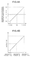
- the magnetic position sensor having the configuration mentioned above has an operating angle of an angle ⁇ , and as shown in Fig. 3A, a line of magnetic force flows as shown at a time when the rotor 1 is positioned at an end of rotation in a clockwise direction, and as shown in Fig. 4A, the magnetic flux passing through the hole element 40 becomes -A.
- the magnetic flux passing through the hole element 40 becomes 0 as shown in Fig. 4A.
- the magnetic flux passing through the hole element 40 becomes +A as shown in Fig. 4C.
- a voltage value in proportion to the rotation angle of the rotor 1 is output from the hole element 40, as shown in Fig. 4B.
- the magnetic position sensor can be made compact, simple in structure and light, it is preferable when detecting the rotation angle of the acceleration grip in the motor cycle or the like.
- Figs. 5 and 6 shows another embodiment of the magnetic position sensor of the rotor type according to the present invention.
- the magnetic position sensor is provided with a permanent magnet piece 110 integrally fixed to a rotor 101 supported by a rotary shaft S in such a manner as to freely oscillate, a first stator 120 and a second stator 130 arranged in an inner side in a diametrical direction of the rotor 101, two hole elements 140 arranged between the first stator 120 and the second stator 130 and serving as a magnetic sensor, an armature 150 arranged in an outer side in the diametrical direction of the rotor 101 and forming a magnetic path, and the like, as a basic configuration.
- the permanent magnet piece 110 is formed, as shown in Fig. 5, so as to constitute an inner circular arc surface 110a and an outer circular arc surface 110b which are concentric with a rotation center C of the rotor 101 so as to be integrally formed with the rotor 101. Further, the permanent magnet piece 110 formed in the circular arc shape is magnetized in different polarities (N pole and S pole) in an inner half and an outer half in a diametrical direction passing through the rotation center C of the rotor 101, and is magnetized so that the polarity reverses on the boundary of a center portion in a rotation direction R of the rotor 101.
- the first stator 120 is arranged, as shown in Figs. 5 and 6, so as to be fixed to an area in an inner side in the diametrical direction of the rotor 101 (and the permanent magnet piece 110) and is formed so as to have an outer circular arc surface 120a which is concentric with the rotation center C of the rotor 101, and the outer circular arc surface 120a opposes to an inner circular arc surface 110a of the permanent magnet piece 110. Then, a portion close to the outer circular arc surface 120a forms a magnetic pole portion 121.
- the second stator 130 is arranged, as shown in Figs. 5 and 6, so as to be fixed to an area in an inner side in a diametrical direction of the rotor 101 (and the permanent magnet piece 110) and a further inner area of the first stator 120, and is constituted by a recess portion 131 receiving the first stator 120, and two magnetic pole portions 132 and 133 continuously formed in both sides of the recess curved portion 131.
- Two magnetic pole portions 132 and 133 are respectively formed so as to have outer circular arc surfaces 132a and 133a concentric with the rotation center C of the rotor 101, on the contrary, the recess portion 131 is formed in a flat surface 131a, and the hole elements 40 is gripped between the flat surface 131a and a flat surface 120b of the first stator 120. Further, outer circular arc surfaces 132a and 133a of two magnetic pole portions 132 and 133 form the same cylindrical surface which is flush with the outer circular arc surface 120a of the first stator 120, and oppose to the inner circular arc surface 110b of the permanent magnet piece 110.
- the hole element 140 is such that it detects a change of a magnetic flux passing from the first stator 120 to the second stator 130 or from the second stator 130 to the first stator 120, and outputs a voltage value corresponding to the change as an output signal.
- the hole element utilizing a hole effect is used as a magnetic sensor, however, it may be of other magnetic sensors as long as it can detect the change of the magnetic flux.
- two hole elements 140 are employed, it is possible to operate one when another gets out of order or the like, thereby obtaining a fail-safe function. In addition, it is also possible to set output characteristics of a plurality of hole elements to have different slopes, thereby improving a resolving power.
- the armature 150 is arranged, as shown in Figs. 5 and 6, so as to be fixed to the area in the outer side in the diametrical direction of the rotor 101 (and the permanent magnet piece 110), and is formed in a circular arc shape concentric with the rotation center C of the rotor 101, and an inner circular arc surface 150a thereof opposes to the outer circular arc surface 110b of the permanent magnet piece 110.
- a circular arc length L1 of the armature 150 and a circular arc length L2 of the second stator 130 in a rotational direction R of the rotor 101 are formed as at least a length corresponding to a moving range of the permanent magnet piece 110. Accordingly, even if the rotor 101 rotates, the permanent magnet piece 110 does not protrude out from end portions in both sides of the armature 150 and the second stator 130, whereby a magnetic flux leakage is prevented.
- the armature 150 is formed in a circular arc shape, however, it is possible to employ that continuing in a ring shape.
- a width Ws1 of the first stator 120, a width Ws2 of the second stator 130 and a width Wa of the armature 150 in a thrust direction of the rotor 101 are set to be at least equal or longer than a length Wm + ⁇ obtained by adding a displacement amount ⁇ (a value calculated with also considering a change with age or the like) in the thrust direction of the rotor 101 with also considering an oscillation or the like to a width Wm of the permanent magnet piece 110.
- the permanent magnet piece 110 does not protrude out from the end portion in the width direction of the first stator 120 and the second stator 130, and the armature 150, whereby a magnetic leakage can be prevented.
- first stator 120 and the second stator 130 are fixed to the armature 150 by a common holding member 160, a distance Ts between the both becomes always constant, and the magnetic flux passes in a perpendicular direction with respect to each of the circular arc surfaces, a stable sensing can be executed. That is , when the rotation center C of the rotor 101 is biased (shifted) due to a dispersion of an accuracy of size or an abrasion of the bearing portion, or the like, a distance T1 between the first stator 120 and the second stator 130, and the permanent magnet piece 110, and a distance T2 between the armature 150 and the permanent magnet piece 110 are changed, as shown in Fig. 5.
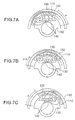
- the magnetic position sensor having the configuration mentioned above has an operating angle of an angle ⁇ , and as shown in Fig. 7A, a line of magnetic force flows as shown at a time when the rotor 101 is positioned at an end of rotation in a counterclockwise direction, and as shown in Fig. 4A described above, the magnetic flux passing through the hole element 140 becomes -A.
- the magnetic flux passing through the hole element 140 becomes 0 as shown in Fig. 4A mentioned above.
- the rotor 101 rotates at an angle ⁇ /2 in a clockwise direction as shown in Fig.
- the rotating rotor as the movable body, however, it is not limited to this, and it can be of other movable bodies as long as the permanent magnet piece is integrally provided with the movable body, and the configuration in which the stator and the armature are arranged in both sides of the permanent magnet piece is employed.
- Fig. 8 is a block diagram which shows still another embodiment of the magnetic position sensor of the linear type.
- reference numerals 1A and 2A denote a first stator and a second stator serving as a first member.
- Magnetic pole portions 10A and 20A are formed in the first stator 1A and the second stator 2A.
- reference numeral 3A denotes an armature serving as a second member.
- An air gap 4A is formed between the armature 3A, and the first stator 1A and the second stator 2A.
- a permanent magnet 5A is arranged in the air gap 4A, so as to be capable of relatively linearly reciprocating with respect to the first stator 1A, the second stator 2A and the armature 3A.
- the permanent magnet 5A opposes to each of the first stator 1A, the second stator 2A and the armature 3A.
- any one of the first stator 1A, the second stator 2A and the armature 3A, and the side of the permanent magnet 5A is mounted to a movable member (not shown) capable of linearly reciprocating.
- any one of another of the first stator 1A, the second stator 2A and the armature 3A, and the side of the permanent magnet 5A is mounted to a fixed member (not shown).
- a receiving space 6A is formed between the first stator 1A and the second stator 2A so as to be substantially parallel to a linearly reciprocating direction of the movable member .
- One (or a plurality of) magnetic flux detecting element 7A is received in the receiving space 6A.
- the magnetic flux detecting element 7A is such that it detects a change of the magnetic flux so as to output a detected signal.
- the permanent magnet 5A is magnetized so as to have different polarities in a side opposing to the first stator 1A and the second stator 2A and a side opposing to the armature 3A, as shown in Fig. 8, and is magnetized so that the polarity reverses on the boundary of a center portion in the linearly reciprocating direction of the movable member.
- Lengths of the first stator 1A, the second stator 2A and the armature 3A in the linearly reciprocating direction of the movable member (lengths corresponding to the lengths L1 and L2 in Fig. 2) have at least a length equal to or more than a sum of the length in the linearly reciprocating direction of the movable member in the permanent magnet 5A and a linearly reciprocating distance of the movable member.
- Widths of the first stator 1A, the second stator 2A and the armature 3A orthogonal to the linearly reciprocating direction of the movable member have at least a length equal to or more than a sum of a width orthogonal to the linearly reciprocating direction of the movable member in the permanent magnet 5A (a width corresponding to Wm in Fig. 2) and a displacement amount ⁇ in a direction orthogonal to the linearly reciprocating direction of the movable member.
- This linear type magnetic position sensor also provides substantially the same operational effects as those of the rotor type mentioned above.
- the magnetic position sensor of the present invention since that which moves integrally together with the movable body is only the permanent magnet piece, it is possible to execute a sensing stably at a high accuracy without being affected by the bias of the movable body or the like.
- a rotor rotatable around a predetermined axis is employed as the movable body, it is preferable, for example, to detect the rotation angle or the like of the accelerator grip in the motor cycle or the like.
- the movable body is made light, the possibility to have an abrasion of the supporting portion or the like is greatly reduced. Accordingly, high accuracy of the sensor will be kept for its entire lifetime.
Landscapes
- Physics & Mathematics (AREA)
- General Physics & Mathematics (AREA)
- Transmission And Conversion Of Sensor Element Output (AREA)
- Measurement Of Length, Angles, Or The Like Using Electric Or Magnetic Means (AREA)
Abstract
Description
Claims (11)
- A magnetic position sensor comprising:a first member and a second member forming an air gap therebetween;a permanent magnet arranged in the air gap so as to relatively rotate with respect to the first member and the second member, and opposing to each of the first member and the second member;at least one magnetic flux detecting elements arranged in at least one of the first member and the second member, which detects a change of magnetic flux and outputs a magnetic flux signal based on the change of magnetic flux;a rotor to which any one of a side of the first member and the second member, and a side of the permanent magnet is mounted, and capable of rotating around a predetermined axis; anda fixing member to which any one of the side of the first member and the second member, and the side of the permanent magnet is mounted.
- The magnetic position sensor according to claim 1, wherein
the permanent magnet having an outer peripheral side circular arc surface and an inner peripheral side circular arc surface which are concentric with a rotation center of the rotor,
the first member is arranged in an outer side of the permanent magnet, and the inner peripheral side circular arc surface concentric with the rotation center of the rotor is formed in the first member so as to oppose to the outer peripheral side circular arc surface of the permanent magnet, and
the second member is arranged in an inner side of the permanent magnet, and the outer peripheral side circular are surface concentric with the rotation center of the rotor is formed in the second member so as to oppose to the inner peripheral side circular arc surface of the permanent magnet. - The magnetic position sensor according to claim 2, wherein the first member is constituted by a first stator and a second stator in which the inner peripheral side circular arc surfaces are respectively formed, a receiving space is formed between the first stator and the second stator, an outer surface is formed in the first stator in an opposite side to the inner peripheral side circular arc surface, an inner surface opposing to the outer surface of the first stator with respect to the receiving space is formed in the second stator, and the magnetic flux detecting element is received in the receiving space between the outer surface of the first stator and the inner surface of the second stator.
- The magnetic position sensor according to claim 2, wherein the second member is constituted by a first stator and a second stator in which the outer peripheral side circular arc surfaces are respectively formed, a receiving space is formed between the first stator and the second stator, opposing surfaces respectively opposing with respect to the receiving space are respectively formed in the first stator and the second stator, and the magnetic flux detecting element is received between the opposing surface of the first stator and the opposing surface of the second stator in a state of being gripped therebetween.
- The magnetic position sensor according to claim 1, wherein the permanent magnet is magnetized so as to have different polarities in a side opposing to the first member and a side opposing to the second member, and is magnetized so that the polarity reverses on the boundary of a center portion in a rotational direction of the rotor.
- The magnetic position sensor according to claim 1, wherein lengths of the first member and the second member in a rotational direction of the rotor have at least a length equal to or more than a sum of a length of the permanent magnet in the rotational direction of the rotor and a rotational distance of the rotor.
- The magnetic position sensor according to claim 1, wherein widths of the first member and the second member in a thrust direction of the rotor have at least a length equal to or more than a sum of a width of the permanent magnet in the thrust direction of the rotor and a displacement amount in the thrust direction of the rotor.
- A magnetic position sensor comprising:wherein the first member is constituted by a first stator and a second stator, a receiving space is formed between the first stator and the second stator so as to be substantially parallel to a linearly reciprocating direction of the movable member, and the magnetic flux detecting element is received in the receiving space.a first member and a second member forming an air gap therebetween;a permanent magnet arranged in the air gap so as to relatively linearly reciprocate with respect to the first member and the second member, and opposing to each of the first member and the second member;at least one magnetic flux detecting element arranged in the first member, which detects a change of magnetic flux and outputs a magnetic flux signal based on the change of magnetic flux;a movable member to which any one of a side of the first member and the second member, and a side of the permanent magnet is mounted, and capable of linearly reciprocating; anda fixing member to which any one of the side of the first member and the second member, and the side of the permanent magnet is mounted,
- The magnetic position sensor according to claim 8, wherein the permanent magnet is magnetized so as to have different polarities in a side opposing to the first member and a side opposing to the second member, and is magnetized so that the polarity reverses on the boundary of a center portion in a linearly reciprocating direction of the movable member.
- A magnetic position sensor according to claim 8, wherein lengths of the first member and the second member in a linearly reciprocating direction of the movable member have at least a length equal to or more than a sum of a length of the permanent magnet in the linearly reciprocating direction of the movable member and a linearly reciprocating distance of the movable member.
- The magnetic position sensor according to claim 8, wherein widths of the first member and the second member orthogonal to a linearly reciprocating direction of the movable member have at least a length equal to or more than a sum of a width of the permanent magnet orthogonal to the linearly reciprocating direction of the movable member and a displacement amount in the direction orthogonal to the linearly reciprocating direction of the movable member.
Applications Claiming Priority (2)
| Application Number | Priority Date | Filing Date | Title |
|---|---|---|---|
| JP2001104278 | 2001-04-03 | ||
| JP2001104278A JP2002303535A (en) | 2001-04-03 | 2001-04-03 | Magnetic position sensor |
Publications (2)
| Publication Number | Publication Date |
|---|---|
| EP1248075A2 true EP1248075A2 (en) | 2002-10-09 |
| EP1248075A3 EP1248075A3 (en) | 2005-08-03 |
Family
ID=18957165
Family Applications (1)
| Application Number | Title | Priority Date | Filing Date |
|---|---|---|---|
| EP02006646A Withdrawn EP1248075A3 (en) | 2001-04-03 | 2002-03-26 | Magnetic position sensor |
Country Status (3)
| Country | Link |
|---|---|
| US (1) | US6879150B2 (en) |
| EP (1) | EP1248075A3 (en) |
| JP (1) | JP2002303535A (en) |
Cited By (2)
| Publication number | Priority date | Publication date | Assignee | Title |
|---|---|---|---|---|
| FR2950426A1 (en) * | 2009-09-24 | 2011-03-25 | Ratier Figeac Soc | Contactless angular position sensor for measuring small angular position of control sleeve of aircraft, has magnetic sector intercepting apex angle that is greater than or equal to angular displacement and less than specific degrees |
| FR2953805A1 (en) * | 2009-12-15 | 2011-06-17 | Ratier Figeac Soc | DEVICE FOR CONTROLLING AN AIRCRAFT WITH MAGNETO-SENSITIVE ELEMENTS FOR ANGULAR POSITION DETECTION MOUNTED OUT OF AXIS |
Families Citing this family (20)
| Publication number | Priority date | Publication date | Assignee | Title |
|---|---|---|---|---|
| JP4169536B2 (en) * | 2002-06-26 | 2008-10-22 | 株式会社日本自動車部品総合研究所 | Actuator |
| JP4233920B2 (en) * | 2003-05-15 | 2009-03-04 | 株式会社デンソー | Rotation angle detector |
| US20050280322A1 (en) * | 2004-06-21 | 2005-12-22 | Shih-En Tsou | Induction generator for a rotatable object |
| JP2006112879A (en) * | 2004-10-14 | 2006-04-27 | Yamaha Motor Co Ltd | Relative position detection device and saddle riding type vehicle |
| US20070229058A1 (en) * | 2006-03-31 | 2007-10-04 | Wolf Ronald J | Displacement sensor |
| JP5012423B2 (en) * | 2007-10-31 | 2012-08-29 | Tdk株式会社 | Rotation angle detection device and rotation angle detection method |
| JP5012424B2 (en) * | 2007-10-31 | 2012-08-29 | Tdk株式会社 | Rotation angle detection device and rotation angle detection method |
| JP5503914B2 (en) * | 2009-07-30 | 2014-05-28 | 矢崎総業株式会社 | Angle detector |
| US20120242331A1 (en) * | 2009-12-04 | 2012-09-27 | Werner Dengler | Hall-based rotational angle measuring system, in particular for hand-operated throttles |
| JP5285588B2 (en) * | 2009-12-11 | 2013-09-11 | 株式会社日本ロック | Vehicle fall sensor |
| JP2012047624A (en) * | 2010-08-27 | 2012-03-08 | Nippon Seiki Co Ltd | Position detection device |
| DE102010055046A1 (en) * | 2010-12-17 | 2012-06-21 | Continental Automotive Gmbh | Valve |
| EP2716891B1 (en) * | 2011-06-30 | 2016-01-13 | Honda Motor Co., Ltd. | Accelerator opening degree detection device |
| WO2013010292A1 (en) * | 2011-07-21 | 2013-01-24 | Honeywell International Inc. | Non-contact rotational position sensor system |
| JP5961414B2 (en) * | 2012-03-28 | 2016-08-02 | 本田技研工業株式会社 | Throttle opening detection device |
| JP2015145816A (en) * | 2014-02-03 | 2015-08-13 | アイシン精機株式会社 | displacement sensor |
| JP6283860B2 (en) * | 2015-12-14 | 2018-02-28 | ミネベアミツミ株式会社 | Angle detection device and angle detection system |
| NL1042415B1 (en) * | 2017-06-02 | 2018-12-11 | Idbike B V | Displacement measuring device |
| FR3071605B1 (en) | 2017-09-25 | 2019-09-13 | Moving Magnet Technologies | MODULE FOR DETECTING A ROTARY HANDLE OF A MOTORIZED VEHICLE |
| US10850795B2 (en) * | 2019-01-29 | 2020-12-01 | Asahi Denso Co., Ltd. | Throttle grip device |
Family Cites Families (9)
| Publication number | Priority date | Publication date | Assignee | Title |
|---|---|---|---|---|
| US3751691A (en) * | 1972-04-14 | 1973-08-07 | Sperry Rand Corp | Rotational transducer using hall effect devices |
| US4086519A (en) * | 1977-02-25 | 1978-04-25 | Electro-Craft Corporation | Hall effect shaft angle position encoder |
| EP0193168A3 (en) * | 1985-02-25 | 1989-01-25 | Kubota Limited | Method of inspecting carburization and probe therefor |
| FR2670286B1 (en) | 1990-12-05 | 1993-03-26 | Moving Magnet Tech | MAGNETIC POSITION AND SPEED SENSOR WITH HALL PROBE. |
| FR2715726B1 (en) | 1994-02-01 | 1996-10-18 | Moving Magnet Tech | Magnetic Hall sensor position sensor. |
| FR2691534B1 (en) | 1992-05-19 | 1994-08-26 | Moving Magnet Tech | Permanent magnet position sensor and hall sensor. |
| DE19630764A1 (en) * | 1995-09-29 | 1997-04-03 | Bosch Gmbh Robert | Contact free identification device for relative movement |
| DE19634281C2 (en) * | 1996-08-24 | 2000-01-27 | Bosch Gmbh Robert | Measuring device for contactless detection of an angle of rotation or a linear movement |
| JP4038308B2 (en) * | 1999-09-09 | 2008-01-23 | 株式会社ミクニ | Non-contact position sensor |
-
2001
- 2001-04-03 JP JP2001104278A patent/JP2002303535A/en active Pending
-
2002
- 2002-03-26 US US10/105,183 patent/US6879150B2/en not_active Expired - Fee Related
- 2002-03-26 EP EP02006646A patent/EP1248075A3/en not_active Withdrawn
Cited By (3)
| Publication number | Priority date | Publication date | Assignee | Title |
|---|---|---|---|---|
| FR2950426A1 (en) * | 2009-09-24 | 2011-03-25 | Ratier Figeac Soc | Contactless angular position sensor for measuring small angular position of control sleeve of aircraft, has magnetic sector intercepting apex angle that is greater than or equal to angular displacement and less than specific degrees |
| FR2953805A1 (en) * | 2009-12-15 | 2011-06-17 | Ratier Figeac Soc | DEVICE FOR CONTROLLING AN AIRCRAFT WITH MAGNETO-SENSITIVE ELEMENTS FOR ANGULAR POSITION DETECTION MOUNTED OUT OF AXIS |
| US8314609B2 (en) | 2009-12-15 | 2012-11-20 | Ratier Figeac | Device for piloting an aircraft having off-axis magnetic-field-sensitive elements for detecting angular position |
Also Published As
| Publication number | Publication date |
|---|---|
| EP1248075A3 (en) | 2005-08-03 |
| US20020140299A1 (en) | 2002-10-03 |
| US6879150B2 (en) | 2005-04-12 |
| JP2002303535A (en) | 2002-10-18 |
Similar Documents
| Publication | Publication Date | Title |
|---|---|---|
| US6879150B2 (en) | Magnetic position sensor | |
| US7030606B2 (en) | Angular sensor with a magneto-electric transducer and a magnetic deflection device | |
| EP0543105B1 (en) | Electromagnetic motor of the finite rotational type | |
| JP2842482B2 (en) | Magnetic position and velocity sensor with Hall element | |
| JP4169536B2 (en) | Actuator | |
| EP1211476B1 (en) | Noncontact position sensor | |
| US6414482B1 (en) | Non-contact type rotational angle sensor and sensor core used in the sensor | |
| JP4269961B2 (en) | Rotation angle detector | |
| JP4204294B2 (en) | Rotation angle detector | |
| EP0182652B1 (en) | Rotary driving device used for rotary actuator | |
| JPWO2005040730A1 (en) | Rotation angle detector | |
| US7154262B2 (en) | Rotation angle detecting device | |
| US5763972A (en) | Magnetic bearing with alternating actuators and sensors | |
| US6870364B2 (en) | Connection structure of non-contact rotary sensor with rotating shaft | |
| EP1875155B1 (en) | Rotary position sensor | |
| JP4321665B2 (en) | Rotation angle detector | |
| KR20040001880A (en) | Magnetic position sensor | |
| JP4233920B2 (en) | Rotation angle detector | |
| KR20000070595A (en) | Metering device for contactless determination of a rotation | |
| JP2558631Y2 (en) | Electromagnetic finite rotary motor | |
| JPH03137530A (en) | Displacement sensor and torque sensor | |
| JP3422184B2 (en) | Magnetic rotation angle sensor | |
| GB2339915A (en) | Angle-of-rotation sensor | |
| JP2004122087A (en) | Rotor support structure | |
| JP2001339910A (en) | Finite rotation motor with position sensor |
Legal Events
| Date | Code | Title | Description |
|---|---|---|---|
| PUAI | Public reference made under article 153(3) epc to a published international application that has entered the european phase |
Free format text: ORIGINAL CODE: 0009012 |
|
| AK | Designated contracting states |
Kind code of ref document: A2 Designated state(s): AT BE CH CY DE DK ES FI FR GB GR IE IT LI LU MC NL PT SE TR |
|
| AX | Request for extension of the european patent |
Free format text: AL;LT;LV;MK;RO;SI |
|
| PUAL | Search report despatched |
Free format text: ORIGINAL CODE: 0009013 |
|
| AK | Designated contracting states |
Kind code of ref document: A3 Designated state(s): AT BE CH CY DE DK ES FI FR GB GR IE IT LI LU MC NL PT SE TR |
|
| AX | Request for extension of the european patent |
Extension state: AL LT LV MK RO SI |
|
| 17P | Request for examination filed |
Effective date: 20060116 |
|
| AKX | Designation fees paid |
Designated state(s): DE FR GB IT |
|
| 17Q | First examination report despatched |
Effective date: 20060808 |
|
| STAA | Information on the status of an ep patent application or granted ep patent |
Free format text: STATUS: THE APPLICATION IS DEEMED TO BE WITHDRAWN |
|
| 18D | Application deemed to be withdrawn |
Effective date: 20070220 |