EP1247743A1 - Strap sealer - Google Patents
Strap sealer Download PDFInfo
- Publication number
- EP1247743A1 EP1247743A1 EP02252262A EP02252262A EP1247743A1 EP 1247743 A1 EP1247743 A1 EP 1247743A1 EP 02252262 A EP02252262 A EP 02252262A EP 02252262 A EP02252262 A EP 02252262A EP 1247743 A1 EP1247743 A1 EP 1247743A1
- Authority
- EP
- European Patent Office
- Prior art keywords
- piston
- ram
- cross
- housing
- penetration
- Prior art date
- Legal status (The legal status is an assumption and is not a legal conclusion. Google has not performed a legal analysis and makes no representation as to the accuracy of the status listed.)
- Granted
Links
- 230000035515 penetration Effects 0.000 claims abstract description 33
- 230000009977 dual effect Effects 0.000 claims abstract description 9
- 238000004891 communication Methods 0.000 claims abstract description 6
- 238000007789 sealing Methods 0.000 claims description 20
- 239000012530 fluid Substances 0.000 claims description 7
- 239000000463 material Substances 0.000 description 14
- 230000000694 effects Effects 0.000 description 5
- 238000013022 venting Methods 0.000 description 5
- 229910000831 Steel Inorganic materials 0.000 description 3
- 239000010959 steel Substances 0.000 description 3
- 230000007704 transition Effects 0.000 description 3
- 230000002411 adverse Effects 0.000 description 2
- 238000002788 crimping Methods 0.000 description 2
- 238000000034 method Methods 0.000 description 2
- 238000004519 manufacturing process Methods 0.000 description 1
- 238000004806 packaging method and process Methods 0.000 description 1
- 238000004080 punching Methods 0.000 description 1
- 230000000717 retained effect Effects 0.000 description 1
- 239000002023 wood Substances 0.000 description 1
Images


Classifications
-
- B—PERFORMING OPERATIONS; TRANSPORTING
- B65—CONVEYING; PACKING; STORING; HANDLING THIN OR FILAMENTARY MATERIAL
- B65B—MACHINES, APPARATUS OR DEVICES FOR, OR METHODS OF, PACKAGING ARTICLES OR MATERIALS; UNPACKING
- B65B13/00—Bundling articles
- B65B13/18—Details of, or auxiliary devices used in, bundling machines or bundling tools
- B65B13/24—Securing ends of binding material
- B65B13/34—Securing ends of binding material by applying separate securing members, e.g. deformable clips
- B65B13/345—Hand tools
-
- B—PERFORMING OPERATIONS; TRANSPORTING
- B65—CONVEYING; PACKING; STORING; HANDLING THIN OR FILAMENTARY MATERIAL
- B65B—MACHINES, APPARATUS OR DEVICES FOR, OR METHODS OF, PACKAGING ARTICLES OR MATERIALS; UNPACKING
- B65B13/00—Bundling articles
- B65B13/18—Details of, or auxiliary devices used in, bundling machines or bundling tools
- B65B13/185—Details of tools
- B65B13/187—Motor means
- B65B13/188—Motor means pneumatic or hydraulic
Definitions
- Strap material is widely used for bundling and securing loads. These strapping materials will be commonly recognized as steel or plastic strap that surrounds or encircles a load to secure the load together, e.g., bundle the load. For example, lumber is often bundled and strapped so that the individual pieces of wood are retained within the larger lumber bundle. Many types of articles are held together by strapping material, such as paper, packaging containers, bottles and the like.
- the size and strength of the strap material varies depending upon the load and the tension required in the strap. For example, in the shipping industry where large containers or crates are often secured by strapping material, large width, heavy gauge strapping is used.
- the strapping material When secured around a load, the strapping material must be sealed or secured to itself.
- Various methods and devices are known for effecting these seals.
- One type of strapper forms seals by punching the strapping material to form interlocks between upper and lower layers of the overlapped strapping material. This is commonly referred to as a seal-less strap.
- Another type of strap seal typically for heavier gauge strapping material requires a separate seal that is positioned around the overlapped strapping material. This seal is then crimped at its edges and partially into the body of the seal and strap, transversely, of the seal to crimp the seal and the strapping material together. Deformation type seals such as these are disclosed in US-A-3,089,233 and US-A-3,237,256.
- sealers To form the crimped or deformed seal, many types of sealers are known in the art. Such sealers can be driven electrically, pneumatically or hydraulically.
- One known pneumatic sealer includes a housing having a piston that is positioned within a cylinder. The piston reciprocates to move a linkage to which a pair of jaw elements are connected. The jaw elements close or move together to contact the seal element to effect the crimp or seal.
- air pressure is used to move the piston to close the jaws.
- a spring is positioned at an opposing side of the piston to return the piston to its initial position (to open the jaws). While such an arrangement provides an effective drive for moving the jaws together, the spring continually acting on the piston tends to require an increased air pressure to move the jaws closed. In the event that the air pressure is constant, the spring slows down the action of the piston, thus slowing the overall sealing operation.
- an effective sealer device that utilizes compressed air for driving a piston for moving the sealer jaws.
- a pneumatic sealer is fast-acting to both the sealing and opening positions, that is, to form the seal and to return to the ready position.
- a strap sealer has a dual action piston and a seal forming assembly operably connected to the piston.
- the sealer includes a housing that defines a cylinder.
- the housing has a penetration therein.
- a piston is disposed in the cylinder for reciprocating movement therein.
- the piston has first and second sides and defines upper and lower pressure regions at the first and second sides of the piston.
- the sealer forms a seal in a seal element and the underlying steel strapping.
- the seal can be of the crimped or deformed type, or may be of the notch-type, in which notches are cut into the seal element and the underlying strapping material, which notched portions may also be bent to enhance seal integrity.
- the piston reciprocates to move a linkage to which a pair of jaw elements are connected.
- the jaw elements close or move together to contact the seal element to effect the crimp or seal.
- the seal can be formed by crimping or by "notching" into the seal and the straps around which the seal is positioned.
- the dual action piston uses compressed gas, preferably compressed air to move the piston to close the jaw elements and to move the piston to open the jaw elements.
- a gas inlet is in flow communication with first and second flow paths that extend between the inlet and the upper and lower pressure regions.
- a valve arrangement provides flow communication between the inlet and the first and second flow paths to supply and exhaust gas to the upper and lower pressure regions.
- a ram is mounted to the piston for reciprocating movement therewith.
- the ram traverses through the housing penetration.
- the ram has first and second cross-sectional areas that are different from each other.
- the ram reciprocates through the housing penetration.
- the and the first cross-sectional area resides at the housing penetration, it forms a seal therebetween.
- the second cross-sectional area passes through the housing penetration a vent path is provided from the lower pressure region outwardly to vent gas from the lower pressure region.
- the present sealer uses a compressed gas, preferably compressed air for driving the piston for moving the sealer jaws.
- the present sealer uses compressed air, without a spring assist to move the piston.
- the present dual action piston is fast-acting to both the sealing and opening positions, that is, to form the seal and to return to the ready or at-rest position.
- the first and second cross-sectional areas of the ram are defined by an undercut region in the ram.
- the undercut region is defined by at least first and second different diameters.
- the undercut includes flats extending along a portion of the ram.
- the seal forming assembly includes jaw elements that are moveable toward and away from one another between the open condition and the closed position for forming the strap seal.
- the vent path from the lower pressure region exhausts air from the lower pressure region when the jaw elements are moved from the open condition to the closed position.
- the vent path can vent to the seal forming assembly.
- the sealer includes a sealing element at the housing penetration.
- the sealing element can be an O-ring or like flexible element.
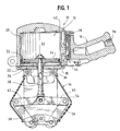
- the sealer 10 includes generally a housing 12, a seal forming assembly 14 and a handle 16.
- the seal forming assembly 14 is mounted to a base 18 of the housing 12.
- the base 18 is preferably mounted to the housing 12 by fasteners (not shown), such as screws, bolts or the like.
- the handle 16 extends from the housing 12 and can be formed as part of the housing 12. Alternately, the handle 16 can be mounted to the housing 12 in a sealed arrangement.
- the housing 12 defines a cylinder 20 in which a piston 22 is mounted for reciprocating movement between a sealing or closed position as shown in FIG. 1, and an at-rest or open position as shown in FIG. 2.
- FIG. 3 is a transitional view of the piston 22 as is moves from the open position to the closed position.
- the piston 22 is a dual-action piston. That is, pressurized fluid is applied to move the piston 22 in both directions. To this end, the piston 22 has upper and lower surfaces 24,26, both of which are configured for having pressurized fluid applied to them.
- a ram 28 is sealingly mounted to the piston 22 for reciprocating movement therewith.
- the ram 28 defines a stem mounted to the piston 22, that traverse through a penetration 30 in the housing 12 at the base 18 thereof.
- the piston 22 is sealed at its periphery, against the cylinder 20 wall, by sealing element 32 such as the exemplary O-ring.
- a sealing element 34 such as the exemplary O-ring is positioned at the penetration 30 and forms a seal at the housing penetration 30 for the ram 28.
- the handle 16 is configured to provide a grip for the sealer 10.
- the handle 16 can be configured having an fluid (such as air or pneumatic supply) inlet 36 for the sealer tool 10.
- a valve assembly 38 resides in a valve sleeve 40 that is positioned between the supply inlet 36 and first and second flow paths (as indicated at 42 and 44, respectively) between the supply 36 and the cylinder 20.
- valve assembly 38 is positioned in the sleeve 40 in the handle 16 (or at about a transition of the handle 16 and the housing 12).
- the first and second flow paths 42, 44 are formed in the housing 12 extending from the valve assembly 38 through the housing 12 into upper and lower pressure regions (as indicated at 46 and 48, respectively) of the cylinder 20.
- a trigger 50 is mounted to the housing 12 at about the handle 16.
- the trigger 50 engages a valve stem 52 that actuates the valve assembly 38.
- the valve assembly 38 is configured to direct fluid, presently contemplated to be compressed air, into and to vent air from, both the upper and lower pressure regions 46,48 of the cylinder 20, as described below.
- the seal forming assembly 14 includes an outer boot 54, first and second, opposing jaw elements 56, 58 and a linkage, having first and second linkage arms 60, 62 that extend between and operably connect the jaw elements 56, 58 and the ram 28. To this end, the ram 28 extends through the housing 12, at the penetration 30, into the seal forming assembly 14.
- the jaws 56, 58 close (as seen in FIG. 1) onto a seal that is positioned around the overlapping strapping material.
- the jaws 56, 58 can be configured to crimp the seal, as by deformation, or can be configured to "cut" notches into the seal and the underlying strapping. The notches may be further bent to enhance seal integrity. All such sealing methods are encompassed by the term crimping as used herein.
- the ram 28 moves along with the piston 22 to urge the sealer links 60,62 upwardly to open the jaw elements 56, 58. Conversely, as the piston 22 moves from the at-rest position to the sealing position, the ram 28 is urged downwardly urging the sealer links 60,62 away from one another to close the jaw elements 56, 58.
- valve stem 52 reciprocates within the bore 40, opening the flow paths 42,44 to the upper and lower pressure regions 46,48.
- the valve stem 52 is formed having upper and lower sealing lobes 64, 66 and a central flow passage 68 between the lobes 64, 66.
- the valve assembly 38 includes a plurality of valve sleeves 96a-c positioned within the bore 40 and separated from one another by seals 98a-b, such as the exemplary O-rings.
- the sleeves 96a-c are formed having openings 99 therein to provide flow communication between the inlet 36 and the flow paths 42,44 and the exhaust ports 70, 74 and the flow paths 42,44.
- a present assembly 38 includes three valve sleeves, one each associated with the inlet 36, the upper pressure region flow path 42 and the lower pressure region flow path 44.
- the stem 52 reciprocates upward by actuation of or engagement by the trigger 50 (to route air to the upper pressure region 46) to position the central flow passage 68 between the upper region sleeve 96a and the inlet sleeve 96b.
- compressed air flows from the inlet 36 through the openings in sleeve 96b, around flow passage 68, through upper region sleeve 96a openings, and into flow path 42.
- the upper lobe 64 isolates the upper exhaust port 74, by forming a seal at the lobe 64/O-ring 98a juncture to prevent venting the upper pressure region 46.
- the lower lobe 66 is positioned (and forms a seal) between the inlet sleeve 96k and the lower pressure region sleeve 96c. This isolates the flow of compressed air to the lower pressure region flow path 44.
- the lower pressure region flow path 44 is open to the stem exhaust port 70 through the openings in sleeve 96c
- the stem 52 reciprocates downward (to route air to the lower pressure region 48) by the return action of the spring 72.
- This locates the central flow passage 68 between the lower region sleeve 96c and the inlet sleeve 96b.
- compressed air flows from the inlet 36 through the openings in sleeve 96b, around the central passage 68, through sleeve 96c openings, and into flow path 44.
- the lower lobe 66 is positioned to isolate the stem exhaust port 70, by forming a seal at the lobe 66/O-ring 98d juncture to prevent venting the lower pressure region 48.
- the upper lobe 64 When in this stem 52 position, the upper lobe 64 is positioned (and forms a seal) between the inlet sleeve 96b and the upper pressure region sleeve 96a. This isolates the flow of compressed air to the upper pressure region flow path 42.
- the upper pressure region flow path 42 is open to the exhaust port 74 through the openings in sleeve 96a, up through the spring 72, and out through the port 74.
- the exhaust port 74 thus provides an opening to the environment to exhaust or vent air from the upper pressure region 46.
- the valve 38 has a novel arrangement to provide for adjustment to assure that air is directed from and to the proper paths.
- a threaded cap 100 (threads not shown) maintains the valve assembly 38 intact within the bore 40.
- the cap 100 includes a central well 102 that defines a plug 104.
- a bearing surface 106 at an end of the plug 104 bears against a resilient element 108 having a bore 110 through the center thereof.
- a rigid element 112 is aligned with the resilient element 108, which rigid element 112 also has a bore 114 through the center thereof.
- the resilient element 108 can be formed of rubber, various appropriate polymeric materials and the like, and rigid element 112 can be formed of, for example, steel.
- the rigid element 112 is positioned on the uppermost O-ring 98a.
- the spring 72 is positioned in the cap well 102 and extends through the resilient and rigid element center bores 110, 114, respectively.
- the spring 72 resides within a well 116 in a top of the stem 52 and applies the force to return the stem 52 to the downward position (as illustrated in FIG. 7) to pressurize the lower pressure region 48 and vent the upper pressure region 46.
- the cap 110 By threading the cap 110 inward of the housing 12 (i.e., tightening down the cap 100), an increased force is exerted onto the resilient and rigid elements 108, 112. This force compresses the O-rings 98a-d, which results in the O-rings 98a-d flattening longitudinally and expanding radially inwardly and outwardly. This reduces the inside diameter across each of the O-rings 98a-d, which in turn “tighten” around the lobes 64, 66. This effectively reduces leakage across the valve assembly 38.
- the cap 100 can be "tightened” or “loosened” to reduce leakage or to facilitate movement of the stem 52 within the sleeves 96a-c and O-rings 98a-d.
- the ram 28 interconnects the piston 22 and the seal forming assembly 14. To this end, the ram 28 traverses through the housing penetration 30 and extends between the piston 22 and the linkage arms 60, 62.
- the present sealer 10 provides an additional flow or vent path, as best seen in FIG. 3, as indicated at 78, for venting the lower pressure region 48 during the closing stroke (that is moving from the at-rest position to the closed position). It has been found that this venting capability provided by this additional vent path 78 reduces the stroke time in moving the piston 22 through this closing stroke.
- the present 10 sealer includes an undercut portion (as indicated generally at 80 in FIGS. 4-5) in the ram 28, which undercut portion 80 traverses through the housing penetration 30 during piston 22 stroke.
- the undercut portion 80 includes a narrowed diameter 82 along an intermediate portion 84 of the ram 28 between the linkage connection 86 and the piston connection 88.
- the ram 28 has a circular cross-section or cylindrical shape that conforms to the penetration 30 with the seal 34 in place.
- a complete seal is formed between the ram 28 and the penetration 30 (by the seal 34), when the piston 22 is at the fully open or fully closed position.
- the reduced ram shaft diameter at the undercut portion 80 establishes a flow path 78 between the lower pressure region 48 and the seal forming assembly 14, through the penetration 30, past seal 34.
- the flow path 78 is essentially established from the lower pressure region 48 to the environs, thus assisting the venting of the lower pressure region 48.
- the undercut 80 is formed in the ram 28 to reduce the overall cross-sectional area of the ram 28.
- a width w 1 dimension of the ram 28 is reduced at a first reduced section 90.
- the reduced width section 90 results in "flats", as indicated at 92, that extend along a second reduced portion 94 of the ram 28.
- the flats 92 transition into the first reduced diameter portion 90 which, further along transitions to the linkage connection 86.
- the portion of the ram indicated generally at 80 which portion traverses through the housing penetration 30, has two reduced cross-sectional areas (the first and second reduced diameter portions 90, 94), as compared to the full cross-sectional areas (as indicated at 96, 98) adjacent the, linkage and piston connections that provide this additional vent path 78.
- the reduced cross-sectional area of the undercut portion 80 provides the additional vent path 78 from the lower pressure region 48, which increases the overall flow area for exhausting air from the lower pressure region 48 when the sealer 10 is actuated and the piston 22 moves from the at-rest position to the sealing position.
- this increased flow area thus reduces the resistance to movement of the piston 22 from the at-rest position to the sealing position without additional mechanical assistance, such as springs and the like.
Landscapes
- Engineering & Computer Science (AREA)
- Mechanical Engineering (AREA)
- Sealing Devices (AREA)
- Basic Packing Technique (AREA)
- Seal Device For Vehicle (AREA)
- Package Closures (AREA)
- Actuator (AREA)
Abstract
Description
- Strap material is widely used for bundling and securing loads. These strapping materials will be commonly recognized as steel or plastic strap that surrounds or encircles a load to secure the load together, e.g., bundle the load. For example, lumber is often bundled and strapped so that the individual pieces of wood are retained within the larger lumber bundle. Many types of articles are held together by strapping material, such as paper, packaging containers, bottles and the like.
- The size and strength of the strap material varies depending upon the load and the tension required in the strap. For example, in the shipping industry where large containers or crates are often secured by strapping material, large width, heavy gauge strapping is used.
- When secured around a load, the strapping material must be sealed or secured to itself. Various methods and devices are known for effecting these seals. One type of strapper forms seals by punching the strapping material to form interlocks between upper and lower layers of the overlapped strapping material. This is commonly referred to as a seal-less strap. Another type of strap seal, typically for heavier gauge strapping material requires a separate seal that is positioned around the overlapped strapping material. This seal is then crimped at its edges and partially into the body of the seal and strap, transversely, of the seal to crimp the seal and the strapping material together. Deformation type seals such as these are disclosed in US-A-3,089,233 and US-A-3,237,256.
- To form the crimped or deformed seal, many types of sealers are known in the art. Such sealers can be driven electrically, pneumatically or hydraulically. One known pneumatic sealer includes a housing having a piston that is positioned within a cylinder. The piston reciprocates to move a linkage to which a pair of jaw elements are connected. The jaw elements close or move together to contact the seal element to effect the crimp or seal. In such a pneumatic sealer, air pressure is used to move the piston to close the jaws. A spring is positioned at an opposing side of the piston to return the piston to its initial position (to open the jaws). While such an arrangement provides an effective drive for moving the jaws together, the spring continually acting on the piston tends to require an increased air pressure to move the jaws closed. In the event that the air pressure is constant, the spring slows down the action of the piston, thus slowing the overall sealing operation.
- In addition, it has also been found that in this spring return arrangement, the jaws can get "hung-up" on the seal and the spring does not have sufficient force return the piston from the closed state to the open state.
- It will be recognized that in many industries in which these sealers are used, such as manufacturing or shipping industries, the time that is afforded an operator to form these seals is minimal. As such, tools having slow response times, or tools that get "hung-up" are not acceptable in the workplace.
- Accordingly, there exists a need for an effective sealer device that utilizes compressed air for driving a piston for moving the sealer jaws. Desirably, such a pneumatic sealer is fast-acting to both the sealing and opening positions, that is, to form the seal and to return to the ready position.
- According to this invention a strap sealer has a dual action piston and a seal forming assembly operably connected to the piston. The sealer includes a housing that defines a cylinder. The housing has a penetration therein. A piston is disposed in the cylinder for reciprocating movement therein. The piston has first and second sides and defines upper and lower pressure regions at the first and second sides of the piston.
- The sealer forms a seal in a seal element and the underlying steel strapping. The seal can be of the crimped or deformed type, or may be of the notch-type, in which notches are cut into the seal element and the underlying strapping material, which notched portions may also be bent to enhance seal integrity.
- The piston reciprocates to move a linkage to which a pair of jaw elements are connected. The jaw elements close or move together to contact the seal element to effect the crimp or seal. The seal can be formed by crimping or by "notching" into the seal and the straps around which the seal is positioned.
- The dual action piston uses compressed gas, preferably compressed air to move the piston to close the jaw elements and to move the piston to open the jaw elements. A gas inlet is in flow communication with first and second flow paths that extend between the inlet and the upper and lower pressure regions. A valve arrangement provides flow communication between the inlet and the first and second flow paths to supply and exhaust gas to the upper and lower pressure regions.
- A ram is mounted to the piston for reciprocating movement therewith. The ram traverses through the housing penetration. The ram has first and second cross-sectional areas that are different from each other.
- As the piston reciprocates within the housing the ram reciprocates through the housing penetration. When the ram reciprocates through the housing penetration the and the first cross-sectional area resides at the housing penetration, it forms a seal therebetween. When the second cross-sectional area passes through the housing penetration a vent path is provided from the lower pressure region outwardly to vent gas from the lower pressure region.
- Advantageously, the present sealer uses a compressed gas, preferably compressed air for driving the piston for moving the sealer jaws. The present sealer uses compressed air, without a spring assist to move the piston. Thus, there is no constant back force on the piston as it drives the jaws closed. The present dual action piston is fast-acting to both the sealing and opening positions, that is, to form the seal and to return to the ready or at-rest position.
- In a current embodiment, the first and second cross-sectional areas of the ram are defined by an undercut region in the ram. Preferably, the undercut region is defined by at least first and second different diameters. Most preferably, the undercut includes flats extending along a portion of the ram.
- In the current embodiment, the seal forming assembly includes jaw elements that are moveable toward and away from one another between the open condition and the closed position for forming the strap seal. The vent path from the lower pressure region exhausts air from the lower pressure region when the jaw elements are moved from the open condition to the closed position. The vent path can vent to the seal forming assembly.
- In a preferred embodiment, the sealer includes a sealing element at the housing penetration. The sealing element can be an O-ring or like flexible element.
- A particular embodiment in accordance with this invention will now be described with reference to the accompanying drawings; in which:-
- FIG. 1 is a partial cross-sectional illustration of an exemplary sealer having a fast-acting dual action piston in accordance with the present invention, the sealer being illustrated in the sealing state;
- FIG. 2 is a partial cross-sectional view of the sealer of FIG. 1 with the piston in the at-rest state;
- FIG. 3 is a partial cross-sectional view of a portion of the piston illustrating the ram traversing through the housing penetration, as the piston moves from the at-rest state to the sealing stats;
- FIG. 4 is a front view (as seen from FIGs. 1-3) of the undercut ram used in the present sealer;
- FIG. 5 is a side-view of the ram of FIG. 4;
- FIG. 6 is an enlarged, partial cross-sectional view of the valve assembly illustrated in a position corresponding to that of the piston being in the sealing state of FIG. 1; and,
- FIG. 7 is a an enlarged, partial cross-sectional view of the valve assembly illustrated in a position corresponding to that of the piston being in the at-rest state of FIG. 2.
-
- Referring now to the figures and in particular to FIG. 1, there is shown an
exemplary sealer 10 having a fast-acting dual action piston embodying the principles of the present invention. Thesealer 10 includes generally ahousing 12, aseal forming assembly 14 and ahandle 16. Theseal forming assembly 14 is mounted to abase 18 of thehousing 12. Thebase 18 is preferably mounted to thehousing 12 by fasteners (not shown), such as screws, bolts or the like. Thehandle 16 extends from thehousing 12 and can be formed as part of thehousing 12. Alternately, thehandle 16 can be mounted to thehousing 12 in a sealed arrangement. - The
housing 12 defines acylinder 20 in which apiston 22 is mounted for reciprocating movement between a sealing or closed position as shown in FIG. 1, and an at-rest or open position as shown in FIG. 2. FIG. 3 is a transitional view of thepiston 22 as is moves from the open position to the closed position. - The
piston 22 is a dual-action piston. That is, pressurized fluid is applied to move thepiston 22 in both directions. To this end, thepiston 22 has upper andlower surfaces - A
ram 28 is sealingly mounted to thepiston 22 for reciprocating movement therewith. Essentially, theram 28 defines a stem mounted to thepiston 22, that traverse through apenetration 30 in thehousing 12 at thebase 18 thereof. Thepiston 22 is sealed at its periphery, against thecylinder 20 wall, by sealingelement 32 such as the exemplary O-ring. A sealingelement 34, such as the exemplary O-ring is positioned at thepenetration 30 and forms a seal at thehousing penetration 30 for theram 28. - The
handle 16 is configured to provide a grip for thesealer 10. In addition, as illustrated in theexemplary sealer 10, thehandle 16 can be configured having an fluid (such as air or pneumatic supply)inlet 36 for thesealer tool 10. Avalve assembly 38 resides in avalve sleeve 40 that is positioned between thesupply inlet 36 and first and second flow paths (as indicated at 42 and 44, respectively) between thesupply 36 and thecylinder 20. - In a present embodiment, the
valve assembly 38 is positioned in thesleeve 40 in the handle 16 (or at about a transition of thehandle 16 and the housing 12). The first andsecond flow paths housing 12 extending from thevalve assembly 38 through thehousing 12 into upper and lower pressure regions (as indicated at 46 and 48, respectively) of thecylinder 20. - A
trigger 50 is mounted to thehousing 12 at about thehandle 16. Thetrigger 50 engages avalve stem 52 that actuates thevalve assembly 38. Thevalve assembly 38 is configured to direct fluid, presently contemplated to be compressed air, into and to vent air from, both the upper andlower pressure regions cylinder 20, as described below. - The
seal forming assembly 14 includes anouter boot 54, first and second, opposingjaw elements second linkage arms jaw elements ram 28. To this end, theram 28 extends through thehousing 12, at thepenetration 30, into theseal forming assembly 14. - As will be recognized by those skilled in the art, the
jaws jaws - As the
piston 22 moves from the sealing position (FIG. 1) to the at-rest position (FIG. 2), theram 28 moves along with thepiston 22 to urge the sealer links 60,62 upwardly to open thejaw elements piston 22 moves from the at-rest position to the sealing position, theram 28 is urged downwardly urging the sealer links 60,62 away from one another to close thejaw elements - Referring now to FIG. 1, when in the sealing position, compressed air is supplied to the
upper pressure region 46 through the flow path indicted at 42, and air is vented from thelower pressure region 48 through the flow path indicated at 44. Conversely, as seen in FIG. 2, when in the at-rest position, compressed air is supplied to thelower pressure region 48 throughflow path 44 and air is vented from theupper pressure region 46 throughflow path 42. - Referring now to FIGS. 6 and 7, to effect this redirection of compressed air supply and exhaust, the
valve stem 52 reciprocates within thebore 40, opening theflow paths lower pressure regions lower sealing lobes central flow passage 68 between thelobes valve assembly 38 includes a plurality ofvalve sleeves 96a-c positioned within thebore 40 and separated from one another byseals 98a-b, such as the exemplary O-rings. Thesleeves 96a-c are formed havingopenings 99 therein to provide flow communication between theinlet 36 and theflow paths exhaust ports 70, 74 and theflow paths present assembly 38 includes three valve sleeves, one each associated with theinlet 36, the upper pressure region flowpath 42 and the lower pressure region flowpath 44. - As best seen in FIG. 6, the
stem 52 reciprocates upward by actuation of or engagement by the trigger 50 (to route air to the upper pressure region 46) to position thecentral flow passage 68 between theupper region sleeve 96a and theinlet sleeve 96b. In this position, compressed air flows from theinlet 36 through the openings insleeve 96b, aroundflow passage 68, throughupper region sleeve 96a openings, and intoflow path 42. At this position, theupper lobe 64 isolates theupper exhaust port 74, by forming a seal at thelobe 64/O-ring 98a juncture to prevent venting theupper pressure region 46. - In this
stem 52 position, thelower lobe 66 is positioned (and forms a seal) between the inlet sleeve 96k and the lowerpressure region sleeve 96c. This isolates the flow of compressed air to the lower pressure region flowpath 44. At this position, the lower pressure region flowpath 44 is open to the stem exhaust port 70 through the openings insleeve 96c - Referring now to FIG. 7, the
stem 52 reciprocates downward (to route air to the lower pressure region 48) by the return action of thespring 72. This locates thecentral flow passage 68 between thelower region sleeve 96c and theinlet sleeve 96b. In this position, compressed air flows from theinlet 36 through the openings insleeve 96b, around thecentral passage 68, throughsleeve 96c openings, and intoflow path 44. At the same time, thelower lobe 66 is positioned to isolate the stem exhaust port 70, by forming a seal at thelobe 66/O-ring 98d juncture to prevent venting thelower pressure region 48. - When in this
stem 52 position, theupper lobe 64 is positioned (and forms a seal) between theinlet sleeve 96b and the upperpressure region sleeve 96a. This isolates the flow of compressed air to the upper pressure region flowpath 42. At the same time, the upper pressure region flowpath 42 is open to theexhaust port 74 through the openings insleeve 96a, up through thespring 72, and out through theport 74. Theexhaust port 74 thus provides an opening to the environment to exhaust or vent air from theupper pressure region 46. Those skilled in the art will, from a study of the drawings, recognize and appreciate thevalve assembly 38 arrangement and operation. - The
valve 38 has a novel arrangement to provide for adjustment to assure that air is directed from and to the proper paths. A threaded cap 100 (threads not shown) maintains thevalve assembly 38 intact within thebore 40. Thecap 100 includes acentral well 102 that defines aplug 104. A bearingsurface 106 at an end of theplug 104 bears against aresilient element 108 having abore 110 through the center thereof. Arigid element 112 is aligned with theresilient element 108, whichrigid element 112 also has abore 114 through the center thereof. Theresilient element 108 can be formed of rubber, various appropriate polymeric materials and the like, andrigid element 112 can be formed of, for example, steel. - The
rigid element 112 is positioned on the uppermost O-ring 98a. Thespring 72 is positioned in the cap well 102 and extends through the resilient and rigid element center bores 110, 114, respectively. Thespring 72 resides within a well 116 in a top of thestem 52 and applies the force to return thestem 52 to the downward position (as illustrated in FIG. 7) to pressurize thelower pressure region 48 and vent theupper pressure region 46. - By threading the
cap 110 inward of the housing 12 (i.e., tightening down the cap 100), an increased force is exerted onto the resilient andrigid elements rings 98a-d, which results in the O-rings 98a-d flattening longitudinally and expanding radially inwardly and outwardly. This reduces the inside diameter across each of the O-rings 98a-d, which in turn "tighten" around thelobes valve assembly 38. Thecap 100 can be "tightened" or "loosened" to reduce leakage or to facilitate movement of thestem 52 within thesleeves 96a-c and O-rings 98a-d. - As set forth above, the
ram 28 interconnects thepiston 22 and theseal forming assembly 14. To this end, theram 28 traverses through thehousing penetration 30 and extends between thepiston 22 and thelinkage arms - The
present sealer 10 provides an additional flow or vent path, as best seen in FIG. 3, as indicated at 78, for venting thelower pressure region 48 during the closing stroke (that is moving from the at-rest position to the closed position). It has been found that this venting capability provided by thisadditional vent path 78 reduces the stroke time in moving thepiston 22 through this closing stroke. - The present 10 sealer includes an undercut portion (as indicated generally at 80 in FIGS. 4-5) in the
ram 28, which undercutportion 80 traverses through thehousing penetration 30 duringpiston 22 stroke. The undercutportion 80 includes a narroweddiameter 82 along anintermediate portion 84 of theram 28 between thelinkage connection 86 and thepiston connection 88. As best seen in FIGS. 4 and 5, at about thepiston connection 88 and thelinkage connection 86, theram 28 has a circular cross-section or cylindrical shape that conforms to thepenetration 30 with theseal 34 in place. Thus, a complete seal is formed between theram 28 and the penetration 30 (by the seal 34), when thepiston 22 is at the fully open or fully closed position. However, as thepiston 22 moves from the at-rest position to the closed position (FIG. 3 indicating an intermediate position), the reduced ram shaft diameter at the undercutportion 80, establishes aflow path 78 between thelower pressure region 48 and theseal forming assembly 14, through thepenetration 30,past seal 34. In that theseal forming assembly 14 is open to the environs, theflow path 78 is essentially established from thelower pressure region 48 to the environs, thus assisting the venting of thelower pressure region 48. - Referring again to FIGS. 4 and 5, the undercut 80 is formed in the
ram 28 to reduce the overall cross-sectional area of theram 28. A width w1 dimension of theram 28 is reduced at a first reducedsection 90. As seen in FIG. 5, the reducedwidth section 90 results in "flats", as indicated at 92, that extend along a second reducedportion 94 of theram 28. Theflats 92 transition into the first reduceddiameter portion 90 which, further along transitions to thelinkage connection 86. To this end, the portion of the ram indicated generally at 80, which portion traverses through thehousing penetration 30, has two reduced cross-sectional areas (the first and second reduceddiameter portions 90, 94), as compared to the full cross-sectional areas (as indicated at 96, 98) adjacent the, linkage and piston connections that provide thisadditional vent path 78. - As will be appreciated by those skilled in the art, the reduced cross-sectional area of the undercut
portion 80 provides theadditional vent path 78 from thelower pressure region 48, which increases the overall flow area for exhausting air from thelower pressure region 48 when thesealer 10 is actuated and thepiston 22 moves from the at-rest position to the sealing position. Those skilled in the art will appreciate that this increased flow area thus reduces the resistance to movement of thepiston 22 from the at-rest position to the sealing position without additional mechanical assistance, such as springs and the like. - It has also been found that the undercut
ram 28 does not adversely effect the return of thepiston 22 from the sealing position to the at-rest position. That is, although there will inherently be a slight increase in the time required to pressurize thelower pressure region 48, this increase in time is not sufficiently great to adversely effect the overall operation of thesealer tool 10.
Claims (10)
- A strap sealer (10) having a dual action piston (12) comprising:wherein as the piston (24) reciprocates within the housing (20) the ram (28) reciprocates through the housing penetration (30), and wherein when the ram (28) reciprocates through the housing penetration (30) and the first cross-sectional area (98) resides at the housing penetration (30) a seal is formed therebetween, and wherein when the ram (28) reciprocates through the housing penetration (30) and the second cross-sectional area (90) passes through the housing penetration (30) a vent path (78) is provided therebetween to vent gas outwardly from the second pressure region.a housing (20) defining a cylinder, the housing defining a penetration (30) therein;a piston (24) disposed in the cylinder (20) for reciprocating movement therein, the piston (24) having first and second sides, the piston defining first (46) and second (48) pressure regions at the first and second sides of the piston (24) ;a gas inlet (36) ;first (42) and second (44) flow paths extending between the gas inlet (36) and the front and second pressure regions (46,48), respectively;a valve arrangement (38) for providing flow communication between the gas inlet (36) and the first and second flow paths (42,44) for supplying gas to the first and second pressure regions (46,48);a ram mounted (28) to the piston (24) for reciprocating movement therewith, the ram (28) traversing through the housing penetration, the ram (28) having first (98) and second (90) cross-sectional areas different from one another; and,a seal forming assembly (56,58) operably connected to the ram (28),
- A strap sealer according to claim 1, wherein the second cross-sectional area of the ram (28) includes an undercut region (90) in the ram (28) having at least first and second different diameters.
- A strap sealer according to claim 1 or 2, wherein the second cross-sectional area of the ram (28) includes flats extending along a portion of the ram (28).
- A strap sealer according to any one of the preceding claims, wherein the seal forming assembly includes jaw elements (56,58) moveable toward and away from one another between an open position and a closed position for closing a seal on a strap.
- A strap sealer according to claim 4, wherein the vent path (78) from the second pressure region (48) exhausts gas from the second pressure region (48) when the jaw elements (56,58) are moved from the open condition to the closed position.
- A strap sealer according to any one of the preceding claims, wherein the vent path (78) vents to the seal forming assembly (56,58).
- A strap sealer according to any one of the preceding claims, including a sealing element (34) at the housing penetration (30).
- A strap sealer according to any one of the preceding claims, wherein the ram (28) includes a third cross-sectional area (92) different from the first (98) and second (90) cross-sectional areas.
- A strap sealer according to claim 8, wherein the third cross-sectional area (92) is less than the first cross-sectional area (98) and is greater than the second cross-sectional area (90).
- A strap sealer having a dual action piston comprising:a housing defining a cylinder, the housing defining a penetration therein;a piston disposed in the cylinder for reciprocating movement therein;upper and lower pressure regions defined by the piston in the cylinder;a compressed fluid inlet;first and second flow paths extending between the compressed fluid inlet and the upper and lower pressure regions, respectively, the first and second flow paths providing flow communication between the compressed fluid inlet and the upper and lower pressure regions;a stem mounted to the piston for reciprocating movement therewith, the stem traversing through the housing penetration, the stem having first and second cross-sectional areas, the first cross-sectional area being greater than the second cross-sectional area, wherein when the second cross-sectional area resides at the penetration a third flow path is provided from the lower pressure region outwardly to vent the lower pressure region; anda seal forming assembly operably connected to the stem.
Applications Claiming Priority (2)
| Application Number | Priority Date | Filing Date | Title |
|---|---|---|---|
| US09/826,342 US6422272B1 (en) | 2001-04-04 | 2001-04-04 | Strap sealer with fast-acting dual action piston |
| US826342 | 2001-04-04 |
Publications (2)
| Publication Number | Publication Date |
|---|---|
| EP1247743A1 true EP1247743A1 (en) | 2002-10-09 |
| EP1247743B1 EP1247743B1 (en) | 2009-08-05 |
Family
ID=25246287
Family Applications (1)
| Application Number | Title | Priority Date | Filing Date |
|---|---|---|---|
| EP02252262A Expired - Lifetime EP1247743B1 (en) | 2001-04-04 | 2002-03-27 | Strap sealer |
Country Status (5)
| Country | Link |
|---|---|
| US (1) | US6422272B1 (en) |
| EP (1) | EP1247743B1 (en) |
| AT (1) | ATE438571T1 (en) |
| CA (1) | CA2378293C (en) |
| DE (1) | DE60233184D1 (en) |
Families Citing this family (13)
| Publication number | Priority date | Publication date | Assignee | Title |
|---|---|---|---|---|
| US7664820B2 (en) * | 2005-03-15 | 2010-02-16 | International Business Machines Corporation | RFID wireless control of instant messaging |
| DE102008018894B3 (en) * | 2008-04-14 | 2010-02-11 | Titan Umreifungstechnik Gmbh & Co. Kg | Pneumatic hand strapping tool |
| US9272799B2 (en) | 2011-10-04 | 2016-03-01 | Signode Industrial Group Llc | Sealing tool for strap |
| US9932135B2 (en) | 2012-09-24 | 2018-04-03 | Signode Industrial Group Llc | Strapping device |
| US10322831B2 (en) | 2014-05-12 | 2019-06-18 | Signode Industrial Group Llc | Reduced power consumption sealing tool for strap |
| US10577137B2 (en) | 2015-12-09 | 2020-03-03 | Signode Industrial Group Llc | Electrically powered combination hand-held notch-type strapping tool |
| JP7271438B2 (en) * | 2017-05-03 | 2023-05-11 | シグノード インダストリアル グループ リミティド ライアビリティ カンパニー | electric stapling device |
| US11174051B2 (en) | 2019-02-15 | 2021-11-16 | Samuel, Son & Co. (Usa) Inc. | Hand held strapping tool |
| US11352153B2 (en) | 2019-05-07 | 2022-06-07 | Signode Industrial Group Llc | Strapping tool |
| US20230002091A1 (en) * | 2020-05-05 | 2023-01-05 | Yang Bey Industrial Co., Ltd. | Packing strap length cutting apparatus |
| KR20230036121A (en) | 2020-07-13 | 2023-03-14 | 시그노드 인더스트리얼 그룹 엘엘씨 | strapping tool |
| US12420966B2 (en) | 2022-02-18 | 2025-09-23 | Signode Industrial Group Llc | Strapping tool with energy-release feature |
| US12397943B2 (en) | 2022-11-29 | 2025-08-26 | Samuel, Son & Co. (Usa) Inc. | Handheld strapping device |
Citations (4)
| Publication number | Priority date | Publication date | Assignee | Title |
|---|---|---|---|---|
| US1764911A (en) * | 1926-05-10 | 1930-06-17 | Signode Steel Strapping Co | Pneumatic strap sealer |
| GB896398A (en) * | 1959-08-14 | 1962-05-16 | Packers Supply Company Ltd | Improvements in and relating to powered tools for applying binding strapping, wire and the like about articles |
| US3329178A (en) * | 1965-05-24 | 1967-07-04 | Signode Corp | Strapping tool |
| US3552450A (en) * | 1968-12-10 | 1971-01-05 | Signode Corp | Pneumatic seal-crimping tool for tensioned strapping loops |
Family Cites Families (3)
| Publication number | Priority date | Publication date | Assignee | Title |
|---|---|---|---|---|
| US3089233A (en) | 1959-12-28 | 1963-05-14 | Signode Steel Strapping Co | Ligature joining |
| US3237256A (en) | 1962-06-04 | 1966-03-01 | Signode Corp | Seal for ligature joint |
| US4289175A (en) * | 1979-11-13 | 1981-09-15 | Signode Corporation | Tension sensing mechanism for power-operated push-type strapping and sealing tool |
-
2001
- 2001-04-04 US US09/826,342 patent/US6422272B1/en not_active Expired - Lifetime
-
2002
- 2002-03-22 CA CA002378293A patent/CA2378293C/en not_active Expired - Lifetime
- 2002-03-27 EP EP02252262A patent/EP1247743B1/en not_active Expired - Lifetime
- 2002-03-27 DE DE60233184T patent/DE60233184D1/en not_active Expired - Lifetime
- 2002-03-27 AT AT02252262T patent/ATE438571T1/en not_active IP Right Cessation
Patent Citations (4)
| Publication number | Priority date | Publication date | Assignee | Title |
|---|---|---|---|---|
| US1764911A (en) * | 1926-05-10 | 1930-06-17 | Signode Steel Strapping Co | Pneumatic strap sealer |
| GB896398A (en) * | 1959-08-14 | 1962-05-16 | Packers Supply Company Ltd | Improvements in and relating to powered tools for applying binding strapping, wire and the like about articles |
| US3329178A (en) * | 1965-05-24 | 1967-07-04 | Signode Corp | Strapping tool |
| US3552450A (en) * | 1968-12-10 | 1971-01-05 | Signode Corp | Pneumatic seal-crimping tool for tensioned strapping loops |
Also Published As
| Publication number | Publication date |
|---|---|
| CA2378293A1 (en) | 2002-10-04 |
| ATE438571T1 (en) | 2009-08-15 |
| EP1247743B1 (en) | 2009-08-05 |
| US6422272B1 (en) | 2002-07-23 |
| CA2378293C (en) | 2007-01-09 |
| DE60233184D1 (en) | 2009-09-17 |
Similar Documents
| Publication | Publication Date | Title |
|---|---|---|
| EP1247743B1 (en) | Strap sealer | |
| CA2432353C (en) | Dual motor strapper | |
| US6079605A (en) | Quick exhaust remote trigger valve for fastener driving tool | |
| CA2240040C (en) | Pneumatic circuit for strapping tool having adjustable tension control | |
| CN1307077C (en) | Time-out indicator for pneumatic strapper | |
| EP1167200B1 (en) | Manual crimping tool and clip for sealing ends of strapping | |
| AU634627B2 (en) | Time-control circuit for pneumatically operable devices | |
| EP2252513B1 (en) | Improved strapping tool | |
| US5431089A (en) | Force generating mechanism | |
| EP1741631B1 (en) | An improved small profile strapping tool | |
| US3552450A (en) | Pneumatic seal-crimping tool for tensioned strapping loops | |
| EP1857367B1 (en) | Reduced force sealless connection mechanism | |
| US6554030B2 (en) | Progressive punch | |
| US4763562A (en) | Poppet valve with improved seal for pneumatic fastener driving apparatus | |
| US20050252570A1 (en) | Manual crimping tool for plastic strap | |
| CA2543819C (en) | Dual motor strapper | |
| KR102186284B1 (en) | Detachable auto clamp device | |
| GB2023072A (en) | Package strapping tools | |
| US20080066631A1 (en) | Strap seal and system | |
| JPS6341290Y2 (en) |
Legal Events
| Date | Code | Title | Description |
|---|---|---|---|
| PUAI | Public reference made under article 153(3) epc to a published international application that has entered the european phase |
Free format text: ORIGINAL CODE: 0009012 |
|
| AK | Designated contracting states |
Kind code of ref document: A1 Designated state(s): AT BE CH CY DE DK ES FI FR GB GR IE IT LI LU MC NL PT SE TR |
|
| AX | Request for extension of the european patent |
Free format text: AL;LT;LV;MK;RO;SI |
|
| 17P | Request for examination filed |
Effective date: 20030326 |
|
| AKX | Designation fees paid |
Designated state(s): AT BE CH CY DE DK ES FI FR GB GR IE IT LI LU MC NL PT SE TR |
|
| 17Q | First examination report despatched |
Effective date: 20070910 |
|
| GRAP | Despatch of communication of intention to grant a patent |
Free format text: ORIGINAL CODE: EPIDOSNIGR1 |
|
| GRAS | Grant fee paid |
Free format text: ORIGINAL CODE: EPIDOSNIGR3 |
|
| GRAA | (expected) grant |
Free format text: ORIGINAL CODE: 0009210 |
|
| AK | Designated contracting states |
Kind code of ref document: B1 Designated state(s): AT BE CH CY DE DK ES FI FR GB GR IE IT LI LU MC NL PT SE TR |
|
| REG | Reference to a national code |
Ref country code: GB Ref legal event code: FG4D |
|
| REG | Reference to a national code |
Ref country code: CH Ref legal event code: EP |
|
| REG | Reference to a national code |
Ref country code: IE Ref legal event code: FG4D |
|
| REF | Corresponds to: |
Ref document number: 60233184 Country of ref document: DE Date of ref document: 20090917 Kind code of ref document: P |
|
| PG25 | Lapsed in a contracting state [announced via postgrant information from national office to epo] |
Ref country code: AT Free format text: LAPSE BECAUSE OF FAILURE TO SUBMIT A TRANSLATION OF THE DESCRIPTION OR TO PAY THE FEE WITHIN THE PRESCRIBED TIME-LIMIT Effective date: 20090805 Ref country code: FI Free format text: LAPSE BECAUSE OF FAILURE TO SUBMIT A TRANSLATION OF THE DESCRIPTION OR TO PAY THE FEE WITHIN THE PRESCRIBED TIME-LIMIT Effective date: 20090805 Ref country code: ES Free format text: LAPSE BECAUSE OF FAILURE TO SUBMIT A TRANSLATION OF THE DESCRIPTION OR TO PAY THE FEE WITHIN THE PRESCRIBED TIME-LIMIT Effective date: 20091116 Ref country code: SE Free format text: LAPSE BECAUSE OF FAILURE TO SUBMIT A TRANSLATION OF THE DESCRIPTION OR TO PAY THE FEE WITHIN THE PRESCRIBED TIME-LIMIT Effective date: 20090805 |
|
| NLV1 | Nl: lapsed or annulled due to failure to fulfill the requirements of art. 29p and 29m of the patents act | ||
| PG25 | Lapsed in a contracting state [announced via postgrant information from national office to epo] |
Ref country code: NL Free format text: LAPSE BECAUSE OF FAILURE TO SUBMIT A TRANSLATION OF THE DESCRIPTION OR TO PAY THE FEE WITHIN THE PRESCRIBED TIME-LIMIT Effective date: 20090805 |
|
| PG25 | Lapsed in a contracting state [announced via postgrant information from national office to epo] |
Ref country code: PT Free format text: LAPSE BECAUSE OF FAILURE TO SUBMIT A TRANSLATION OF THE DESCRIPTION OR TO PAY THE FEE WITHIN THE PRESCRIBED TIME-LIMIT Effective date: 20091205 |
|
| PG25 | Lapsed in a contracting state [announced via postgrant information from national office to epo] |
Ref country code: DK Free format text: LAPSE BECAUSE OF FAILURE TO SUBMIT A TRANSLATION OF THE DESCRIPTION OR TO PAY THE FEE WITHIN THE PRESCRIBED TIME-LIMIT Effective date: 20090805 |
|
| PLBE | No opposition filed within time limit |
Free format text: ORIGINAL CODE: 0009261 |
|
| STAA | Information on the status of an ep patent application or granted ep patent |
Free format text: STATUS: NO OPPOSITION FILED WITHIN TIME LIMIT |
|
| PG25 | Lapsed in a contracting state [announced via postgrant information from national office to epo] |
Ref country code: BE Free format text: LAPSE BECAUSE OF FAILURE TO SUBMIT A TRANSLATION OF THE DESCRIPTION OR TO PAY THE FEE WITHIN THE PRESCRIBED TIME-LIMIT Effective date: 20090805 |
|
| 26N | No opposition filed |
Effective date: 20100507 |
|
| PG25 | Lapsed in a contracting state [announced via postgrant information from national office to epo] |
Ref country code: GR Free format text: LAPSE BECAUSE OF FAILURE TO SUBMIT A TRANSLATION OF THE DESCRIPTION OR TO PAY THE FEE WITHIN THE PRESCRIBED TIME-LIMIT Effective date: 20091106 Ref country code: MC Free format text: LAPSE BECAUSE OF NON-PAYMENT OF DUE FEES Effective date: 20100331 |
|
| REG | Reference to a national code |
Ref country code: CH Ref legal event code: PL |
|
| PG25 | Lapsed in a contracting state [announced via postgrant information from national office to epo] |
Ref country code: IE Free format text: LAPSE BECAUSE OF NON-PAYMENT OF DUE FEES Effective date: 20100327 |
|
| PG25 | Lapsed in a contracting state [announced via postgrant information from national office to epo] |
Ref country code: CH Free format text: LAPSE BECAUSE OF NON-PAYMENT OF DUE FEES Effective date: 20100331 Ref country code: LI Free format text: LAPSE BECAUSE OF NON-PAYMENT OF DUE FEES Effective date: 20100331 |
|
| PG25 | Lapsed in a contracting state [announced via postgrant information from national office to epo] |
Ref country code: CY Free format text: LAPSE BECAUSE OF FAILURE TO SUBMIT A TRANSLATION OF THE DESCRIPTION OR TO PAY THE FEE WITHIN THE PRESCRIBED TIME-LIMIT Effective date: 20090805 |
|
| PG25 | Lapsed in a contracting state [announced via postgrant information from national office to epo] |
Ref country code: LU Free format text: LAPSE BECAUSE OF NON-PAYMENT OF DUE FEES Effective date: 20100327 |
|
| PG25 | Lapsed in a contracting state [announced via postgrant information from national office to epo] |
Ref country code: TR Free format text: LAPSE BECAUSE OF FAILURE TO SUBMIT A TRANSLATION OF THE DESCRIPTION OR TO PAY THE FEE WITHIN THE PRESCRIBED TIME-LIMIT Effective date: 20090805 |
|
| REG | Reference to a national code |
Ref country code: GB Ref legal event code: 732E Free format text: REGISTERED BETWEEN 20140424 AND 20140430 |
|
| REG | Reference to a national code |
Ref country code: GB Ref legal event code: 732E Free format text: REGISTERED BETWEEN 20140717 AND 20140723 |
|
| REG | Reference to a national code |
Ref country code: DE Ref legal event code: R081 Ref document number: 60233184 Country of ref document: DE Owner name: PREMARK PACKAGING LLC, GLENVIEW, US Free format text: FORMER OWNER: ILLINOIS TOOL WORKS INC., COOK COUNTY, ILL., US Effective date: 20140729 Ref country code: DE Ref legal event code: R081 Ref document number: 60233184 Country of ref document: DE Owner name: SIGNODE INTERNATIONAL IP HOLDINGS LLC, GLENVIE, US Free format text: FORMER OWNER: ILLINOIS TOOL WORKS INC., COOK COUNTY, ILL., US Effective date: 20140729 |
|
| REG | Reference to a national code |
Ref country code: FR Ref legal event code: TP Owner name: PREMARK PACKAGING LLC, US Effective date: 20140827 |
|
| REG | Reference to a national code |
Ref country code: DE Ref legal event code: R081 Ref document number: 60233184 Country of ref document: DE Owner name: SIGNODE INTERNATIONAL IP HOLDINGS LLC, GLENVIE, US Free format text: FORMER OWNER: PREMARK PACKAGING LLC, GLENVIEW, ILL., US Effective date: 20140912 |
|
| REG | Reference to a national code |
Ref country code: FR Ref legal event code: TP Owner name: SIGNODE INTERNATIONAL IP HOLDINGS LLC, US Effective date: 20150127 |
|
| REG | Reference to a national code |
Ref country code: FR Ref legal event code: PLFP Year of fee payment: 15 |
|
| REG | Reference to a national code |
Ref country code: FR Ref legal event code: PLFP Year of fee payment: 16 |
|
| REG | Reference to a national code |
Ref country code: FR Ref legal event code: PLFP Year of fee payment: 17 |
|
| PGFP | Annual fee paid to national office [announced via postgrant information from national office to epo] |
Ref country code: DE Payment date: 20200327 Year of fee payment: 19 Ref country code: IT Payment date: 20200323 Year of fee payment: 19 Ref country code: GB Payment date: 20200327 Year of fee payment: 19 |
|
| PGFP | Annual fee paid to national office [announced via postgrant information from national office to epo] |
Ref country code: FR Payment date: 20200325 Year of fee payment: 19 |
|
| REG | Reference to a national code |
Ref country code: DE Ref legal event code: R119 Ref document number: 60233184 Country of ref document: DE |
|
| GBPC | Gb: european patent ceased through non-payment of renewal fee |
Effective date: 20210327 |
|
| PG25 | Lapsed in a contracting state [announced via postgrant information from national office to epo] |
Ref country code: DE Free format text: LAPSE BECAUSE OF NON-PAYMENT OF DUE FEES Effective date: 20211001 Ref country code: GB Free format text: LAPSE BECAUSE OF NON-PAYMENT OF DUE FEES Effective date: 20210327 Ref country code: FR Free format text: LAPSE BECAUSE OF NON-PAYMENT OF DUE FEES Effective date: 20210331 |
|
| PG25 | Lapsed in a contracting state [announced via postgrant information from national office to epo] |
Ref country code: IT Free format text: LAPSE BECAUSE OF NON-PAYMENT OF DUE FEES Effective date: 20210327 |