EP1247735B1 - Verfahren zur Reduzierung von Schwingungen in einem Hohlraum und überströmte Flächenanordnung - Google Patents
Verfahren zur Reduzierung von Schwingungen in einem Hohlraum und überströmte Flächenanordnung Download PDFInfo
- Publication number
- EP1247735B1 EP1247735B1 EP02003770A EP02003770A EP1247735B1 EP 1247735 B1 EP1247735 B1 EP 1247735B1 EP 02003770 A EP02003770 A EP 02003770A EP 02003770 A EP02003770 A EP 02003770A EP 1247735 B1 EP1247735 B1 EP 1247735B1
- Authority
- EP
- European Patent Office
- Prior art keywords
- cavity
- flow
- delta wing
- flow direction
- longitudinal vortex
- Prior art date
- Legal status (The legal status is an assumption and is not a legal conclusion. Google has not performed a legal analysis and makes no representation as to the accuracy of the status listed.)
- Expired - Lifetime
Links
Images


Classifications
-
- B—PERFORMING OPERATIONS; TRANSPORTING
- B64—AIRCRAFT; AVIATION; COSMONAUTICS
- B64C—AEROPLANES; HELICOPTERS
- B64C21/00—Influencing air flow over aircraft surfaces by affecting boundary layer flow
- B64C21/02—Influencing air flow over aircraft surfaces by affecting boundary layer flow by use of slot, ducts, porous areas or the like
-
- B—PERFORMING OPERATIONS; TRANSPORTING
- B64—AIRCRAFT; AVIATION; COSMONAUTICS
- B64C—AEROPLANES; HELICOPTERS
- B64C2230/00—Boundary layer controls
- B64C2230/06—Boundary layer controls by explicitly adjusting fluid flow, e.g. by using valves, variable aperture or slot areas, variable pump action or variable fluid pressure
-
- B—PERFORMING OPERATIONS; TRANSPORTING
- B64—AIRCRAFT; AVIATION; COSMONAUTICS
- B64C—AEROPLANES; HELICOPTERS
- B64C2230/00—Boundary layer controls
- B64C2230/20—Boundary layer controls by passively inducing fluid flow, e.g. by means of a pressure difference between both ends of a slot or duct
-
- Y—GENERAL TAGGING OF NEW TECHNOLOGICAL DEVELOPMENTS; GENERAL TAGGING OF CROSS-SECTIONAL TECHNOLOGIES SPANNING OVER SEVERAL SECTIONS OF THE IPC; TECHNICAL SUBJECTS COVERED BY FORMER USPC CROSS-REFERENCE ART COLLECTIONS [XRACs] AND DIGESTS
- Y02—TECHNOLOGIES OR APPLICATIONS FOR MITIGATION OR ADAPTATION AGAINST CLIMATE CHANGE
- Y02T—CLIMATE CHANGE MITIGATION TECHNOLOGIES RELATED TO TRANSPORTATION
- Y02T50/00—Aeronautics or air transport
- Y02T50/10—Drag reduction
Definitions
- the invention relates to a method for reducing vibrations in one Cavity, wherein the opening of the cavity of a flow in a flow direction is overflowed.
- the invention further relates to an overflow area arrangement with a cavity, wherein the opening of the cavity of a flow in a flow direction can be overflowed.
- aerodynamic buoyancy bodies are known via the cavity in the Near the rear wall to attach to the appearance and emergence of the shear layer in the cavity to suppress. This also allows the cavity vibrations very good in the entire printing spectrum.
- the disadvantage is However, the cavity opening partially blocked by the buoyancy body, so that this embodiment can not be used in weapons shafts in fighter aircraft is.
- the object of the invention was therefore to provide an improved method for reducing indicate vibrations in a cavity that is reliable, cost-effective and is simple and as independent as possible from the technical constraints and the shape of the cavity can be performed.
- the object is achieved by generating a longitudinal vortex pair flow with two Longitudinal vortex structures on the side edges of the cavity in the flow direction solved, wherein the rotational direction of the two longitudinal vortex structures of the Longitudinal vortex pair flow in opposite directions and the two longitudinal vortex structures are directed so that the right located in the flow direction Longitudinal vortex structure rotates clockwise and the left in the flow direction located longitudinal vortex structure rotates counterclockwise.
- the longitudinal swirl structures induced along the entire side edge of the cavity opening cause a destruction of the quasi two - dimensionality of the Shear layer.
- the stability characteristic of the cavity shear layer changed and stabilized.
- the pair induces longitudinal swirl structures Speed components normal to the cavity opening in the Flow, which raise the cavity shear layer and thereby the inclination of the Reduce the cavity shear layer to interact with the cavity backside.
- the longitudinal vortex structures are also generic large-scale, stationary flow structures, the little or no additional turbulence and instationarity induce, so that no increase in the broadband spectrum of the pressure signals takes place in the cavity. In addition to the tonal signal components are so even the broadband shares also reduced.
- the direction of rotation of the longitudinal swirl structures is directed so that the Longitudinal vortex flows cause a suction from the cavity. This has quasi an air suction result.
- the longitudinal vortex structures are preferably arranged by a Delta wing generated in the area in front of the cavity seen in the flow direction.
- the delta wing has two stall edges that are arrow-shaped converge in the flow direction.
- the delta wing stretches transverse to the flow direction parallel to a flow plane passing through the surface the opening of the cavity is defined.
- the stall edges are running thus upstream arrow-shaped relatively pointed together. At the stall edges the flow is deflected so that it swirls in the longitudinal direction and each inducing a longitudinal swirling structure.
- the sweep angle ⁇ of the delta wing in each case between a stall edge and the transversely to the flow direction extending trailing edge of the delta wing should be about 70 °.
- the angle of attack ⁇ of the delta wing between the surface of the delta wing and the flow area is preferably variable and during the flight at open cavity set to about 10 °.
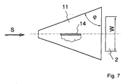
- the span of the delta wing downstream in the area of the opening of the Cavity should be about 1.5 times the width of the cavity. On In this way, the longitudinal vortex structures optimally at the side edges of the Cavity induced.
- the object is achieved by a device in the area in front of the cavity in the flow direction seen to produce a longitudinal swirl pair flow with two Longitudinal vortex structures in the region of the side edges of the cavity in the flow direction solved, wherein the two longitudinal vortex structures in opposite directions to each other have running direction of rotation and the right in the flow direction located longitudinal vortex structure rotates clockwise and in the flow direction left longitudinal vortex structure rotates counterclockwise.
- a device for adjusting the angle of attack ⁇ of the delta wing coupled to the delta wing.
- a pivot axis in front portion of the delta wing be provided a pivot axis, wherein the delta wing is pivotable about the pivot axis.
- Figures 1a and 1b leave an aircraft 1 with a cavity 2 at the bottom of the fuselage as a half section in plan view (a) and in cross section (b) recognize.
- the cavity 2, z. B. a weapons shaft of a combat aircraft has a length L in the flow direction S, a depth D and a width W. In flight, the flow is essentially transonic when the plane is 1 moves at a speed of about 0.8 to 1.3 Mach.
- FIG. 2 shows a cavity 2 in cross-section.
- the cavity 2 is in a Installed surface arrangement 5, which is overflowed in the flow direction S.
- the cavity shear layer 6 which is hydrodynamically unstable and as a result tends to spatially sound wave movements. hereby the cavity shear layer 6 continuously dips into the cavity 2 and again, which is outlined by the arrow 7. As a result, the cavity back wall 8 temporarily exposed to the full flow on the surface arrangement 5, which builds up on the cavity rear wall 8 and generates a pressure pulse, the sound pressure portion 9 within the cavity 2 to the cavity front wall 10 leads. At the upper edge of the cavity front wall is then a new unstable wave in the cavity shear layer 6 is excited, so that a feedback and amplification of the vibration effect is effected.
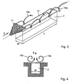
- FIG. 3 shows a perspective view of a cavity 2 with a delta wing 11, in the area in front of the cavity 2 in the flow direction S is arranged seen.
- the so-called delta wing 11 has a pair of stall edges that oppose the flow direction S converge arrow-shaped. In the plan view is the delta wing 11 thus delta or triangular. Transverse to the flow direction S seen, the delta wing 11 extends parallel to the flow plane, the is defined by the opening 12 of the cavity 2.
- the longitudinal vortex structures 13a and 13b have such in opposite directions extending rotational direction, as outlined in Figure 4, that they have a Create suction out of the cavity 2.
- FIG. 4 shows the cavity 2 in cross section in the flow direction S. detect. It is clear that the longitudinal swirl structures 13a and 13b with formed their swirl axis respectively in the region of the side edges of the cavity 2 are.
- the longitudinal vortex structure 13a located on the right in the flow direction S rotates clockwise and the left in the flow direction S longitudinal vortex structure 13b rotates counterclockwise.
- FIG. 5 shows the delta wing 11 in the direction opposite to the flow direction S detect. It is therefore the trailing edge of the delta wing 11 visible.
- the delta wing 11 consists essentially of a triangular as thin as possible, but stable plate attached to the central axis of the delta wing 11 at a integrally connecting the surface assembly extending transverse spar 14 and is connected via the cross member 14 with the surface structure.
- FIG. 6 shows the delta wing 11 in cross section, which is in the region is arranged in front of the cavity 2.
- the cross member 14 to a pivot axis 15 in the front Area of the delta wing 11 hinged to the surface structure and the Pivot axis 15 is pivotable about an angle ⁇ .
- the angle of attack ⁇ is an angle between the area of the delta wing 11 and the flow plane defined by the area of the opening of the cavity 2 defined is. In flight, the angle of attack ⁇ is preferably set to about 10 °.
- FIG. 7 shows the delta wing 11, which is located in the area in front of the cavity 2 and is arranged directly next to it, can be seen in the plan view. It becomes clear that the cross member 14 extends along the central axis of the delta wing 11 and perpendicular to the surface of the delta wing 11 integrally connected to the delta wing 11 is. The stall edges run counter to the flow direction S arrow-shaped together, with the span of the delta wing about 1.5 times is as large as the width W of the cavity 2.
- the arrow angle ⁇ respectively between a stall edge and the transverse to Flow direction S extending trailing edge of the delta wing 11 is approximately 70 °.
Landscapes
- Engineering & Computer Science (AREA)
- Aviation & Aerospace Engineering (AREA)
- Structures Of Non-Positive Displacement Pumps (AREA)
- Aerodynamic Tests, Hydrodynamic Tests, Wind Tunnels, And Water Tanks (AREA)
- Buildings Adapted To Withstand Abnormal External Influences (AREA)
Description
- Figur 1a -
- schematische Halbschnittansicht auf die Unterseite eines Flugzeuges mit einem Hohlraum;
- Figur 1 b -
- schematische Querschnittsansicht des Flugzeuges mit einem Hohlraum an seiner Unterseite;
- Figur 1c -
- Querschnittsansicht des Hohlraums mit Schallwellen;
- Figur 1d -
- Querschnittsansicht des Hohlraums mit Strukturschwingungen;
- Figur 2 -
- schematische Darstellung eines Hohlraumquerschnitts mit einer Strömungsscherschicht;
- Figur 3 -
- perspektivische Ansicht eines Delta-Flügels im Bereich vor einem Hohlraum zur Erzeugung von Längswirbelstrukturen an den Seitenkanten des Hohlraums;
- Figur 4 -
- Querschnittsansicht eines Hohlraums mit gegenläufig rotierenden Längswirbelstrukturen;
- Figur 5 -
- Ansicht eines Delta-Flügels entgegen der Ausströmrichtung;
- Figur 6 -
- Längsschnittansicht eines verstellbaren Delta-Flügels;
- Figur 7 -
- Draufsicht auf den im Bereich vor dem Hohlraum angeordneten Delta-Flügel.
Claims (14)
- Verfahren zur Reduzierung von Schwingungen in einem Hohlraum (2), wobei die Öffnung (12) des Hohlraumes (2) von einer Strömung in eine Strömungsrichtung (S) überströmt wird, gekennzeichnet durch Erzeugen einer Längswirbelpaarströmung mit zwei Längswirbelstrukturen (13a, 13b) an den Seitenkanten des Hohlraums (2) in Strömungsrichtung (S), wobei die Rotationsrichtung der beiden Längswirbelstrukturen (13a, 13b) der Längswirbelpaarströmung gegenläufig zueinander und die beiden Längswirbelstrukturen (13a, 13b) so gerichtet sind, dass die in Strömungsrichtung (S) rechts befindliche Längswirbelstruktur (13a) im Uhrzeigersinn rotiert und die in Strömungsrichtung (S) links befindliche Längswirbelstruktur (13b) entgegen dem Uhrzeigersinn rotiert.
- Verfahren nach Anspruch 1, gekennzeichnet durch Anordnen von einem Delta-Flügel (11) im Bereich vor dem Hohlraum (2), wobei der Delta-Flügel (11) zwei Strömungsabrisskanten hat, die pfeilförmig entgegen der Strömungsrichtung (S) zusammenlaufen, und wobei sich der Delta-Flügel (11) quer zur Strömungsrichtung (S) parallel zu einer Strömungsebene erstreckt, die durch die Fläche der Öffnung des Hohlraumes (2) definiert ist.
- Verfahren nach Anspruch 2, dadurch gekennzeichnet, dass der Pfeilwinkel ϕ jeweils zwischen einer Strömungsabrisskante und der quer zur Strömungsrichtung (S) verlaufenden Hinterkante des Delta-Flügels etwa 70° beträgt.
- Verfahren nach Anspruch 2 oder 3, dadurch gekennzeichnet, dass der Anstellwinkel α des Delta-Flügels zwischen der Fläche des Delta-Flügels (11) und der Strömungsfläche auf etwa 10° eingestellt ist.
- Verfahren nach Anspruch 4, dadurch gekennzeichnet, das der Anstellwinkel α veränderlich ist.
- Verfahren nach einem der Ansprüche 2 bis 5, dadurch gekennzeichnet, dass die Spannweite des Delta-Flügels (11) etwa 1,5 mal so groß wie die Breite (W) des Hohlraums (2) ist.
- Überströmte Flächenanordnung mit einem Hohlraum (2), wobei die Öffnung (12) des Hohlraums (2) von einer Strömung in einer Strömungsrichtung (S) überströmbar ist, gekennzeichnet durch eine Vorrichtung im Bereich vor dem Hohlraum (2) in Strömungsrichtung (S) gesehen, zur Erzeugung von Längswirbelpaarströmungen mit zwei Längswirbelstrukturen (13a, 13b) im Bereich der Seitenkanten des Hohlraums (2) in Strömungsrichtung (S), wobei die beiden Längswirbelstrukturen (13a, 13b) eine gegenläufig zueinander verlaufende Rotationsrichtung haben, wobei die in Strömungsrichtung (S) rechts befindliche Längswirbelstruktur (13a) im Uhrzeigersinn rotiert und die in Strömungsrichtung (S) links befindliche Längwirbelstruktur (13b) entgegen dem Uhrzeigersinn rotiert.
- Flächenanordnung nach Anspruch 7, dadurch gekennzeichnet, dass die Vorrichtung ein Delta-Flügel (11) ist, der zwei Strömungsabrisskanten hat, die pfeilförmig entgegen der Strömungsrichtung (S) zusammenlaufen, und wobei sich der Delta-Flügel (11) quer zur Strömungsrichtung (S) parallel zu einer Strömungsebene erstreckt, die durch die Fläche der Öffnung des Hohlraums (2) definiert ist.
- Flächenanordnung nach Anspruch 8, dadurch gekennzeichnet, dass der Pfeilwinkel ϕ jeweils zwischen einer Strömungsabrisskante und der quer zur Strömungsrichtung (S) verlaufenden Hinterkante des Delta-Flügels (11) etwa 70° beträgt.
- Flächenanordnung nach einem der Ansprüche 8 oder 9, dadurch gekennzeichnet, dass der Anstellwinkel α des Delta-Flügels (11) zwischen der Fläche des Delta-Flügels (11) und der Strömungsfläche etwa 10° beträgt.
- Flächenanordnung nach einem der Ansprüche 7 bis 10, gekennzeichnet durch eine Vorrichtung zur Verstellung des Anstellwinkels α des Delta-Flügels (11).
- Flächenanordnung nach Anspruch 11, gekennzeichnet durch eine Schwenkachse (15) im vorderen Bereich des Delta-Flügels (11), wobei der Delta-Flügel (11) um die Schwenkachse (15) verschwenkbar ist.
- Flächenanordnung nach einem der Ansprüche 7 bis 12, dadurch gekennzeichnet, dass die Spannweite des Delta-Flügels (11) etwa 1,5 mal so groß wie die Breite (W) des Hohlraums (2) ist.
- Flächenanordnung nach einem der Ansprüche 7 bis 12, dadurch gekennzeichnet, dass die Strömungsabrisskanten des Delta-Flügels (11) scharfkantige Fasen aufweisen.
Applications Claiming Priority (2)
| Application Number | Priority Date | Filing Date | Title |
|---|---|---|---|
| DE10117300A DE10117300B4 (de) | 2001-04-06 | 2001-04-06 | Verfahren zur Reduzierung von Schwingungen in einem Hohlraum und überströmte Flächenanordnung |
| DE10117300 | 2001-04-06 |
Publications (3)
| Publication Number | Publication Date |
|---|---|
| EP1247735A2 EP1247735A2 (de) | 2002-10-09 |
| EP1247735A3 EP1247735A3 (de) | 2004-01-28 |
| EP1247735B1 true EP1247735B1 (de) | 2005-04-20 |
Family
ID=7680705
Family Applications (1)
| Application Number | Title | Priority Date | Filing Date |
|---|---|---|---|
| EP02003770A Expired - Lifetime EP1247735B1 (de) | 2001-04-06 | 2002-02-20 | Verfahren zur Reduzierung von Schwingungen in einem Hohlraum und überströmte Flächenanordnung |
Country Status (3)
| Country | Link |
|---|---|
| EP (1) | EP1247735B1 (de) |
| DE (2) | DE10117300B4 (de) |
| ES (1) | ES2237626T3 (de) |
Cited By (1)
| Publication number | Priority date | Publication date | Assignee | Title |
|---|---|---|---|---|
| CN108045555A (zh) * | 2017-11-30 | 2018-05-18 | 中国航空工业集团公司沈阳飞机设计研究所 | 一种设置于深度开式内埋物品舱前缘的扰流板 |
Families Citing this family (8)
| Publication number | Priority date | Publication date | Assignee | Title |
|---|---|---|---|---|
| DE102009052142B3 (de) * | 2009-11-06 | 2011-07-14 | MTU Aero Engines GmbH, 80995 | Axialverdichter |
| FR2957052B1 (fr) * | 2010-03-03 | 2016-08-05 | Airbus Operations Sas | Dispositif aerodynamique de reduction de vibrations de trappes d'un train d'atterrissage avant d'un avion. |
| SE1651465A1 (en) | 2016-05-17 | 2017-11-18 | Saab Ab | Firing direction limitation device |
| EP3458802B1 (de) | 2016-05-17 | 2021-07-28 | Saab AB | Magazin und kartusche |
| PL3458797T3 (pl) | 2016-05-17 | 2021-12-20 | Saab Ab | Magazynek do wystrzeliwania środków przeciwdziałających |
| EP3458799B1 (de) * | 2016-05-17 | 2021-07-07 | Saab AB | Ausgabe von gegenmassnahmen mit variablem spoiler und startverfahren für eine gegenmassnahme |
| CN112623197B (zh) * | 2020-12-29 | 2023-08-04 | 中国航空工业集团公司西安飞机设计研究所 | 一种空腔噪声控制的分流装置及噪声控制方法 |
| CN114735203B (zh) * | 2022-06-13 | 2022-09-23 | 中国空气动力研究与发展中心高速空气动力研究所 | 一种三棱柱状飞行器武器舱噪声抑制装置 |
Family Cites Families (6)
| Publication number | Priority date | Publication date | Assignee | Title |
|---|---|---|---|---|
| US4174083A (en) * | 1977-04-29 | 1979-11-13 | The Boeing Company | Flow deflector for fluid inlet |
| US4696442A (en) * | 1986-07-14 | 1987-09-29 | The Boeing Company | Vortex generators for inlets |
| US5340054A (en) * | 1991-02-20 | 1994-08-23 | The United States Of America As Represented By The Secretary Of The Navy | Suppressor of oscillations in airframe cavities |
| US5699981A (en) * | 1996-03-18 | 1997-12-23 | The United States Of America As Represented By The Secretary Of The Air Force | Aircraft cavity acoustic resonance suppression system |
| US5772155A (en) * | 1996-06-01 | 1998-06-30 | Nowak; Dieter K. | Aircraft wing flaps |
| US6206326B1 (en) * | 1999-04-12 | 2001-03-27 | The United States Of America As Represented By The Secretary Of The Air Force | Method and apparatus for actively enhancing aircraft weapon separation |
-
2001
- 2001-04-06 DE DE10117300A patent/DE10117300B4/de not_active Expired - Fee Related
-
2002
- 2002-02-20 DE DE50202824T patent/DE50202824D1/de not_active Expired - Lifetime
- 2002-02-20 ES ES02003770T patent/ES2237626T3/es not_active Expired - Lifetime
- 2002-02-20 EP EP02003770A patent/EP1247735B1/de not_active Expired - Lifetime
Cited By (2)
| Publication number | Priority date | Publication date | Assignee | Title |
|---|---|---|---|---|
| CN108045555A (zh) * | 2017-11-30 | 2018-05-18 | 中国航空工业集团公司沈阳飞机设计研究所 | 一种设置于深度开式内埋物品舱前缘的扰流板 |
| CN108045555B (zh) * | 2017-11-30 | 2021-01-19 | 中国航空工业集团公司沈阳飞机设计研究所 | 一种设置于深度开式内埋物品舱前缘的扰流板 |
Also Published As
| Publication number | Publication date |
|---|---|
| EP1247735A2 (de) | 2002-10-09 |
| ES2237626T3 (es) | 2005-08-01 |
| DE50202824D1 (de) | 2005-05-25 |
| EP1247735A3 (de) | 2004-01-28 |
| DE10117300B4 (de) | 2004-04-29 |
| DE10117300A1 (de) | 2002-11-21 |
Similar Documents
| Publication | Publication Date | Title |
|---|---|---|
| DE60004492T2 (de) | Vibrationsangetriebener akustischer strahl, der die ablösung der grenzschicht kontrolliert | |
| DE3782230T2 (de) | Geschoss mit verringertem bodensog. | |
| DE69911630T2 (de) | Lufteinlasskanalsystem für flugzeugtriebwerke | |
| EP1145954B1 (de) | Vorrichtung sowie Verfahren zur Reduzierung von Nachlaufwirbeln hinter Flugzeugen im Landeanflug | |
| DE3876297T2 (de) | Aero-/hydrodynamische tragflaeche. | |
| DE69624679T2 (de) | Drehflugelflugzeug mit wirbelerzeuger zur verminderung von blatt-wirbelgerauschen | |
| DE69104974T2 (de) | Rotorverkleidungsleitwerkanschlussebene einer Hubschrauberleitwerkstruktur. | |
| DE69624301T2 (de) | Verfahren und Vorrichtung zur Verminderung von aerodynamischer Lautstärke eines Flugwerks | |
| DE3018263A1 (de) | Gasturbinenansaugoeffnung und verfahren zum leiten eines ansaugluftstroms | |
| EP1112928A2 (de) | Flügelprofil mit leistungs-steigernder Hinterkante | |
| DE2430885A1 (de) | Verfahren und vorrichtung zum steuern und rueckgewinnen der grenzschicht | |
| EP0071616B1 (de) | Auftriebselement insbesondere für Tragflügel und Schaufeln von Strömungsmaschinen, wie z.B. Luftschrauben und Schiffspropeller | |
| EP2528810B1 (de) | Struktur zur verringerung eines strömungswiderstands eines körpers in einem fluid | |
| DE68907330T2 (de) | Aerodynamische Geräuschunterdrückung für Tragflächenklappen. | |
| EP1312545A2 (de) | Aerodynamisches Profil mit verstellbarer Klappe | |
| EP0572787A1 (de) | Windkanal | |
| DE60131478T3 (de) | Konstruktion eines öffnungsfähigen Fahrzeugdaches | |
| DE10117300B4 (de) | Verfahren zur Reduzierung von Schwingungen in einem Hohlraum und überströmte Flächenanordnung | |
| EP1602575B1 (de) | Trag- oder Leitelement | |
| DE2121486A1 (de) | Luftfahrzeug mit einer Vorrichtung zur Erzeugung eines zusätzlichen Auftriebes | |
| EP2669650B1 (de) | Windkanaldüse und Windkanal | |
| DE102009003084B4 (de) | Verkleidung für eine Auftriebshilfe | |
| EP2568166B1 (de) | Windenergieanlagenrotorblatt mit einer dicken Profilhinterkante | |
| DE69309891T2 (de) | Vorrichtung zur Verbindung von Flügeln mit einer Nabe | |
| DE19964114A1 (de) | Dreidimensionale Hinterkante an Flügelprofilen |
Legal Events
| Date | Code | Title | Description |
|---|---|---|---|
| PUAI | Public reference made under article 153(3) epc to a published international application that has entered the european phase |
Free format text: ORIGINAL CODE: 0009012 |
|
| AK | Designated contracting states |
Kind code of ref document: A2 Designated state(s): AT BE CH CY DE DK ES FI FR GB GR IE IT LI LU MC NL PT SE TR |
|
| AX | Request for extension of the european patent |
Free format text: AL;LT;LV;MK;RO;SI |
|
| PUAL | Search report despatched |
Free format text: ORIGINAL CODE: 0009013 |
|
| AK | Designated contracting states |
Kind code of ref document: A3 Designated state(s): AT BE CH CY DE DK ES FI FR GB GR IE IT LI LU MC NL PT SE TR |
|
| AX | Request for extension of the european patent |
Extension state: AL LT LV MK RO SI |
|
| GRAP | Despatch of communication of intention to grant a patent |
Free format text: ORIGINAL CODE: EPIDOSNIGR1 |
|
| 17P | Request for examination filed |
Effective date: 20040416 |
|
| AKX | Designation fees paid |
Designated state(s): BE DE ES FR GB |
|
| GRAS | Grant fee paid |
Free format text: ORIGINAL CODE: EPIDOSNIGR3 |
|
| RTI1 | Title (correction) |
Free format text: METHOD TO REDUCE OSCILLATIONS IN CAVITIES AND SURFACE ARRANGEMENT IN A FLUID FLOW |
|
| GRAA | (expected) grant |
Free format text: ORIGINAL CODE: 0009210 |
|
| AK | Designated contracting states |
Kind code of ref document: B1 Designated state(s): BE DE ES FR GB |
|
| REG | Reference to a national code |
Ref country code: GB Ref legal event code: FG4D Free format text: NOT ENGLISH |
|
| REF | Corresponds to: |
Ref document number: 50202824 Country of ref document: DE Date of ref document: 20050525 Kind code of ref document: P |
|
| GBT | Gb: translation of ep patent filed (gb section 77(6)(a)/1977) |
Effective date: 20050518 |
|
| REG | Reference to a national code |
Ref country code: ES Ref legal event code: FG2A Ref document number: 2237626 Country of ref document: ES Kind code of ref document: T3 |
|
| PLBE | No opposition filed within time limit |
Free format text: ORIGINAL CODE: 0009261 |
|
| STAA | Information on the status of an ep patent application or granted ep patent |
Free format text: STATUS: NO OPPOSITION FILED WITHIN TIME LIMIT |
|
| ET | Fr: translation filed | ||
| 26N | No opposition filed |
Effective date: 20060123 |
|
| PGFP | Annual fee paid to national office [announced via postgrant information from national office to epo] |
Ref country code: GB Payment date: 20070221 Year of fee payment: 6 |
|
| PGFP | Annual fee paid to national office [announced via postgrant information from national office to epo] |
Ref country code: ES Payment date: 20070226 Year of fee payment: 6 |
|
| PGFP | Annual fee paid to national office [announced via postgrant information from national office to epo] |
Ref country code: BE Payment date: 20070301 Year of fee payment: 6 |
|
| PGFP | Annual fee paid to national office [announced via postgrant information from national office to epo] |
Ref country code: FR Payment date: 20070216 Year of fee payment: 6 |
|
| BERE | Be: lapsed |
Owner name: DEUTSCHES ZENTRUM FUR LUFT- UND RAUMFAHRT E.V. *DL Effective date: 20080228 |
|
| GBPC | Gb: european patent ceased through non-payment of renewal fee |
Effective date: 20080220 |
|
| REG | Reference to a national code |
Ref country code: FR Ref legal event code: ST Effective date: 20081031 |
|
| PG25 | Lapsed in a contracting state [announced via postgrant information from national office to epo] |
Ref country code: BE Free format text: LAPSE BECAUSE OF NON-PAYMENT OF DUE FEES Effective date: 20080228 |
|
| PG25 | Lapsed in a contracting state [announced via postgrant information from national office to epo] |
Ref country code: FR Free format text: LAPSE BECAUSE OF NON-PAYMENT OF DUE FEES Effective date: 20080229 |
|
| REG | Reference to a national code |
Ref country code: ES Ref legal event code: FD2A Effective date: 20080221 |
|
| PG25 | Lapsed in a contracting state [announced via postgrant information from national office to epo] |
Ref country code: GB Free format text: LAPSE BECAUSE OF NON-PAYMENT OF DUE FEES Effective date: 20080220 |
|
| PG25 | Lapsed in a contracting state [announced via postgrant information from national office to epo] |
Ref country code: ES Free format text: LAPSE BECAUSE OF NON-PAYMENT OF DUE FEES Effective date: 20080221 |
|
| REG | Reference to a national code |
Ref country code: DE Ref legal event code: R085 Ref document number: 50202824 Country of ref document: DE |
|
| REG | Reference to a national code |
Ref country code: DE Ref legal event code: R082 Ref document number: 50202824 Country of ref document: DE Representative=s name: GRAMM, LINS & PARTNER PATENT- UND RECHTSANWAEL, DE Ref country code: DE Ref legal event code: R082 Ref document number: 50202824 Country of ref document: DE Representative=s name: ISARPATENT PATENTANWAELTE BEHNISCH, BARTH, CHA, DE Ref country code: DE Ref legal event code: R082 Ref document number: 50202824 Country of ref document: DE Representative=s name: ISARPATENT - PATENTANWAELTE- UND RECHTSANWAELT, DE |
|
| REG | Reference to a national code |
Ref country code: DE Ref legal event code: R082 Ref document number: 50202824 Country of ref document: DE Representative=s name: ISARPATENT PATENTANWAELTE BEHNISCH, BARTH, CHA, DE Ref country code: DE Ref legal event code: R081 Ref document number: 50202824 Country of ref document: DE Owner name: AIRBUS OPERATIONS LTD., FILTON, GB Free format text: FORMER OWNER: AIRBUS OPERATIONS LTD., BRISTOL, GB Ref country code: DE Ref legal event code: R081 Ref document number: 50202824 Country of ref document: DE Owner name: AIRBUS OPERATIONS LTD., FILTON, GB Free format text: FORMER OWNER: DEUTSCHES ZENTRUM FUER LUFT- UND RAUMFAHRT E.V., 51147 KOELN, DE Ref country code: DE Ref legal event code: R082 Ref document number: 50202824 Country of ref document: DE Representative=s name: ISARPATENT - PATENTANWAELTE- UND RECHTSANWAELT, DE |
|
| PGFP | Annual fee paid to national office [announced via postgrant information from national office to epo] |
Ref country code: DE Payment date: 20210217 Year of fee payment: 20 |
|
| REG | Reference to a national code |
Ref country code: DE Ref legal event code: R071 Ref document number: 50202824 Country of ref document: DE |