EP1247707A2 - Wiper blade for cleaning glass panes, in particular of vehicles - Google Patents
Wiper blade for cleaning glass panes, in particular of vehicles Download PDFInfo
- Publication number
- EP1247707A2 EP1247707A2 EP02003790A EP02003790A EP1247707A2 EP 1247707 A2 EP1247707 A2 EP 1247707A2 EP 02003790 A EP02003790 A EP 02003790A EP 02003790 A EP02003790 A EP 02003790A EP 1247707 A2 EP1247707 A2 EP 1247707A2
- Authority
- EP
- European Patent Office
- Prior art keywords
- wiper
- wiper blade
- spring rails
- lubricant
- wiper strip
- Prior art date
- Legal status (The legal status is an assumption and is not a legal conclusion. Google has not performed a legal analysis and makes no representation as to the accuracy of the status listed.)
- Withdrawn
Links
Images

Classifications
-
- B—PERFORMING OPERATIONS; TRANSPORTING
- B60—VEHICLES IN GENERAL
- B60S—SERVICING, CLEANING, REPAIRING, SUPPORTING, LIFTING, OR MANOEUVRING OF VEHICLES, NOT OTHERWISE PROVIDED FOR
- B60S1/00—Cleaning of vehicles
- B60S1/02—Cleaning windscreens, windows or optical devices
- B60S1/04—Wipers or the like, e.g. scrapers
- B60S1/32—Wipers or the like, e.g. scrapers characterised by constructional features of wiper blade arms or blades
- B60S1/38—Wiper blades
- B60S1/3848—Flat-type wiper blade, i.e. without harness
- B60S1/3874—Flat-type wiper blade, i.e. without harness with a reinforcing vertebra
- B60S1/3875—Flat-type wiper blade, i.e. without harness with a reinforcing vertebra rectangular section
- B60S1/3879—Flat-type wiper blade, i.e. without harness with a reinforcing vertebra rectangular section placed in side grooves in the squeegee
-
- B—PERFORMING OPERATIONS; TRANSPORTING
- B60—VEHICLES IN GENERAL
- B60S—SERVICING, CLEANING, REPAIRING, SUPPORTING, LIFTING, OR MANOEUVRING OF VEHICLES, NOT OTHERWISE PROVIDED FOR
- B60S1/00—Cleaning of vehicles
- B60S1/02—Cleaning windscreens, windows or optical devices
- B60S1/04—Wipers or the like, e.g. scrapers
- B60S1/32—Wipers or the like, e.g. scrapers characterised by constructional features of wiper blade arms or blades
- B60S1/38—Wiper blades
- B60S2001/3812—Means of supporting or holding the squeegee or blade rubber
- B60S2001/3817—Means of supporting or holding the squeegee or blade rubber chacterised by a backing strip to aid mounting of squeegee in support
- B60S2001/382—Means of supporting or holding the squeegee or blade rubber chacterised by a backing strip to aid mounting of squeegee in support the backing strip being an essentially planar reinforcing strip, e.g. vertebra
Definitions
- the support element should cover the entire from Wiper blade swept the wiping field as evenly as possible Distribution of the wiper blade contact pressure originating from the wiper arm ensure on the disc.
- the curvature of the Wiper blade must therefore be slightly stronger than that in Wiping field measured strongest on the window to be wiped Curvature because during the wiping operation the wiper strip, or their wiper lip on the window, always press against the pane with a certain force got to.
- the support element thus replaces the complex Support bracket construction with two in the wiper strip arranged spring rails, as in conventional Wiper blades are practiced (DE-OS 15 05 257) because that Supporting element in addition to the distribution of the contact pressure also the necessary cross-bracing of the rubber-elastic wiper strip necessary cross-bracing of the rubber-elastic wiper strip causes.
- this Wiper blades primarily ensure cross stiffening the wiper strip between the claws when the wiper blade shifted across its length across its length becomes.
- this braking effect is at least very much reduced, so that trouble-free Relative movement between the spring rails and the Wiper strip is possible.
- the tension in the Wiper strips are practically turned off so that a satisfactory and noiseless wiping operation possible is.
- the wiper blade is designed appropriately, grip the spring rails at least with one another Vertical stripes in opposite to each other Longitudinal sides of the wiper strip open longitudinal grooves of the Wiper strip.
- the lubricant on the spring rails of the support element is arranged.
- it can but also useful the lubricant on the groove walls of the Arrange the wiper strip.
- the lubricant is firm covering layer connected to its carrier is formed.
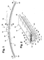
- FIG. 1 shows the basic illustration a wiper blade according to the invention in side view
- figure 2 shows a section through the wiper blade according to FIG. 1 the line II-II, in perspective, stretched and 3 shows the arrangement according to Figure 2 shows another embodiment of the invention.
- a wiper blade 10 shown in FIG Wiping devices in particular for windows from Motor vehicles, has a band-like elongated, resilient support member 12 on the lower, the Disc facing side 13 an elongated, rubber-elastic wiper strip 14 attached to the longitudinal axis is ( Figure 2).
- a connection device arranged, with the help of that Wiper blade 10 articulated with a dash-dotted line, driven wiper arm 16 can be releasably connected ( Figure 1).
- the wiper arm 16 is at its free end with a part, not shown in detail, on the wiper arm side the connection device.
- the wiper blade 16 is in Direction of arrow 20 to the window to be wiped - for example the windshield of a motor vehicle - loaded, the surface in Figure 1 by a Line 22 shown in dash-dotted lines is indicated. Since the Line 22 the strongest curvature of the disc surface should clearly show that the shaping Curvature of the two ends 10 on the disc adjacent, still unloaded wiper blade 10 is stronger than the maximum disc curvature ( Figure 1). Under the Contact pressure (arrow 20) is the wiper blade 10 with its wiper lip 24 along its entire length wiping, unevenly spherically curved Disc surface 22 on.
- connection device is at the same time Articulated connection between the wiper blade and the wiper arm educated.
- the wiper blade 10 or the wiper strip 14 with its wiper lip 24 also the constantly changing during the wiping operation Adjust the course of the disc curvature, what is done by the two Double arrows 28 is indicated in Figure 1.
- This Swinging movement 28 extends from the ends 10 of the Wiper blade 10 or the support element 12 from - steadily decreasing - to the wiper blade part 15 of the Connection device. This inevitably results in one Relative movement between the support member 12 and the Wiper strip 14, in the longitudinal direction thereof, which is shown in FIG is symbolized by the double arrow 30.
- the one spring-elastic steel manufactured support element 12 of Wiper blade 10 two spaced apart and parallel comprises mutually extending spring rails 40.
- the Wiper strip 14 has a cross section seen in essential square base bar 44, with a narrow tilt bar 46 which is the actual wiping work accepting, strip-like wiper lip 24 is connected.
- the Base bar 44 is at their two each other opposite outer or longitudinal sides 41 with each provided an open edge longitudinal groove 42.
- In each of the two Longitudinal grooves 42 is one of the two spring rails 40 of the Carrying element 12 housed.
- the two to the support element 12 belonging spring rails 40 are thus at a distance from each other and parallel to each other in a common Level arranged.
- Securing the two spring rails 40 in its longitudinal grooves 42 can, for example, by the part 15 the connection device and / or by in the drawing not shown, for example with the spring rails lockable securing means are taken over, so that the Wiper strip 14 is held reliably on the support element 12.
- Figure 2 a lubricant on the walls 52, 54, 56 of the longitudinal grooves 42 60 arranged.
- the lubricant 60 is shown in FIG Thickening of the lines representing the groove walls 52, 54, 56 indicated.
- the wiper blade 110 has a structure that is compatible with the structure of the wiper blade according to Figure 2 is comparable. Therefore, in Figure 3, the basic structure of the Parts of the wiper strip 114 which result in the wiper blade have been given the same reference numbers as in FIG. 2 the case is.
- the wiper strip 14 also has one here Base bar 44, which via a tilt bar 46 with a strip-like wiper lip 24 is connected. That is further Base bar 44 at their opposite Outside with one edge open to the long side Longitudinal groove 42 provided, in each of the two longitudinal grooves in each case a spring rail belonging to the support element 112 140 immersed adjacent longitudinal strips 150. Deviating from that previously described with reference to FIG.
- Embodiment are according to the embodiment 3 not the walls of the longitudinal grooves 42 with a Provide lubricant. Rather, here is the lubricant 160 on the surfaces 161, 162, 163 of the spring rails 140 of the Support element 112 arranged. The lubricant 160 covers here at least those immersed in the longitudinal grooves 42 Wall areas of the spring rails 140.
- Lubricant 60 or 160 firmly with the groove walls 52, 54, 56 or fixed with these groove walls facing surfaces 161, 162, 163 of the spring rails 140 connected is. In both cases, for example can be achieved in that the lubricant as Covering layer is formed.
- the arrangement of the lubricant in the manner described above leads to a smoothing of the facing Surfaces so that the spring rails during the Wiping greatly reduced friction and therefore low noise slide in the grooves.
- lubricants Solid lubricants, lubricating varnishes, oils, PTFE, silicone spray, Molid disulfide, graphite also in powder form and so on.
- the application of the lubricant itself can on the predetermined areas of the groove walls and / or on these facing surfaces of the spring rails by dipping, Spraying or painting can be achieved.
- All of the exemplary embodiments have in common that between the Groove walls 52, 54, 56 of the wiper strip 14 and 114 and the these facing surfaces 161, 162, 163 of the spring rails 40 and 140 lubricants 60 and 160 are arranged.
- the spring rails all around to accommodate closed longitudinal channels of the wiper strip. In such a case, all duct walls and / or all surfaces of the spring rails with a lubricant be provided.
- the lubricant is always in the embodiments as Part of the wiper strip or as part of the support element or to look at its spring rails.
- the advantage of the lubricant can also be achieved by a separate one Part, for example by an enclosed slide film can be obtained.
Abstract
Es wird ein Wischblatt vorgeschlagen, dass zum Reinigen von sphärisch gekrümmten Scheiben (22) insbesondere von Kraftfahrzeugen dient. Das Wischblatt (10) hat eine langgestreckte, gummielastische, mit einer Wischlippe (24) an der Scheibe (22) anlegbaren Wischleiste (14), die an einem bandartig langgestreckten, federelastischen Tragelement (12) gehalten ist, welches zwei mit Abstand voneinander und parallel zueinander angeordnete Federschienen (40) hat, die jeweils zumindest mit Längsstreifen (50) in randoffene Längsnuten (42) der Wischleiste (14) greifen, wobei an den Nutwänden (52, 54, 56) der Wischleiste (14) Flächen (161, 162, 163) den Federschienen anliegen. Ein besonders geräuscharmer störungsfreier Wischbetrieb wird gewährleistet, wenn zwischen den Nutwänden (52, 54, 56) der Wischleiste (14) und Flächen der Federschienen (40 bzw. 140) Gleitmittel (60 bzw. 160) angeordnet sind. <IMAGE>A wiper blade is proposed that is used for cleaning spherically curved panes (22), in particular of motor vehicles. The wiper blade (10) has an elongated, rubber-elastic wiper strip (14) which can be placed on the window (22) with a wiper lip (24) and is held on a band-like, elongated, spring-elastic support element (12), which is spaced apart and parallel has mutually arranged spring rails (40) which each engage at least with longitudinal strips (50) in longitudinally open grooves (42) of the wiper strip (14), with surfaces (161, 162) on the groove walls (52, 54, 56) of the wiper strip (14) , 163) rest against the spring rails. A particularly low-noise, trouble-free wiping operation is ensured if lubricants (60 and 160) are arranged between the groove walls (52, 54, 56) of the wiper strip (14) and surfaces of the spring rails (40 and 140). <IMAGE>
Description
Bei Wischblättern der im Oberbegriff des Anspruchs 1
bezeichneten Art soll das Tragelement über das gesamte vom
Wischblatt bestrichene Wischfeld eine möglichst gleichmäßige
Verteilung des vom Wischerarm ausgehenden Wischblatt-Anpressdrucks
an der Scheibe gewährleisten. Durch eine
entsprechende formgebende Krümmung des unbelasteten
Tragelements - also wenn das Wischblatt 10 nur mit seinen
beiden Enden 10 an der Scheibe anliegt (Figur 1) - werden
die Enden der im Betrieb des Wischblatts vollständig an der
Scheibe angelegten Wischleiste durch das dann gespannte
Tragelement zur Scheibe belastet, auch wenn sich die
Krümmungsradien von sphärisch gekrümmten Fahrzeugscheiben
bei jeder Wischblattposition ändern. Die Krümmung des
Wischblatts muss also etwas stärker sein als die im
Wischfeld an der zu wischenden Scheibe gemessene stärkste
Krümmung, weil während des Wischbetriebs die Wischleiste,
beziehungsweise deren an der Scheibe anliegende Wischlippe,
stets mit einer bestimmten Kraft gegen die Scheibe drücken
muss. Das Tragelement ersetzt somit die aufwendige
Tragbügelkonstruktion mit zwei in der Wischleiste
angeordneten Federschienen, wie sie bei herkömmlichen
Wischblättern praktiziert wird (DE-OS 15 05 257), weil das
Tragelement neben der Verteilung des Anpreßdrucks auch die
notwendige Querversteifung der gummielastischen Wischleiste
notwendige Querversteifung der gummielastischen Wischleiste
bewirkt. Bei dem bekannten Wischblatt wird nämlich die von
einem Wischerarm auf einen Hauptbügel ausgeübte, zur Scheibe
gerichtete Auflagekraft auf zwei Krallenbügel übertragen und
von diesen über vier Krallen auf die gummielastische
Wischleiste verteilt. Die beiden Federschienen dieses
Wischblatts sorgen in erster Linie für eine Querversteifung
der Wischleiste zwischen den Krallen, wenn das Wischblatt
quer zu seiner Längserstreckung über die Scheibe verschoben
wird.For wiper blades in the preamble of claim 1
designated type, the support element should cover the entire from
Wiper blade swept the wiping field as evenly as possible
Distribution of the wiper blade contact pressure originating from the wiper arm
ensure on the disc. By a
corresponding shaping curvature of the unloaded
Support element - so if the
Wenn ein bekanntes Wischblatts der im Oberbegriff des Anspruchs 1 bezeichneten Art (DE-OS 19907629) über die ungleichförmig sphärisch gekrümmte Scheibe verschoben wird und das Wischblatt dem Druck des Tragelements beziehungsweise der Oberfläche der Scheibe folgend aus einer seiner Strecklage angenäherten Betriebslage - im Mittelbereich der zu wischenden Scheibe - in seine maximal gekrümmte Betriebslage - in den Randbereichen der Scheibe - verformt wird, ergibt sich zwischen den Flächen der Federschienen des Tragelements und den an diesen anliegenden Nutwänden der Wischleiste eine Relativbewegung in deren Längsrichtung, welche zu Verspannungen im Wischblatt führt. Diese Verspannungen beeinträchtigen das Wischergebnis und führen darüber hinaus zu unerwünschten Quietschgeräuschen während des Wischbetriebs, weil durch den bezüglich der Federschienen ungünstigen Reibwert des für die Wischleiste notwendigen Materials eine diese Relativbewegung störende Bremswirkung an den Federschienen zustande kommt. Auch kann sich eine Versteifung der Wischleiste und damit eine Beeinträchtigung des Wischergebnisses ergeben, wenn in die Längsnuten eintretendes Wasser gefriert. If a known wiper blade in the preamble of Claim 1 designated type (DE-OS 19907629) on the non-uniform spherically curved disc is displaced and the wiper blade to the pressure of the support element or following the surface of the disk from a its stretched position approximate operating position - in Middle area of the window to be wiped - in its maximum curved operating position - in the edge areas of the disc - is deformed, results between the surfaces of the Spring rails of the support element and the adjoining them Groove walls of the wiper strip a relative movement in their Longitudinal direction, which leads to tension in the wiper blade. These tensions affect the wiping result and also lead to undesirable squeaking noises during the wiping operation because of the Spring rails unfavorable coefficient of friction for the wiper strip necessary material disturbing this relative movement Braking effect on the spring rails comes about. Can too stiffening of the wiper strip and thus one Impairment of the wiping result if in the Water entering longitudinal grooves freezes.
Bei dem erfindungsgemäßen Wischblatt mit den kennzeichnenden Merkmalen des Anspruchs 1 wird diese Bremswirkung zumindest sehr stark reduziert, so dass eine störungsfreie Relativbewegung zwischen den Federschienen und der Wischleiste möglich ist. Die Verspannungen in der Wischleiste werden damit praktisch abgestellt, so dass ein zufriedenstellender und geräuschloser Wischbetrieb möglich ist. Auch wird einer dauerhaften Vereisung der Wischleiste vorgebeugt, weil eine dort vorhandene Eisschicht am Gleitmittel keinen Halt findet und rasch aus den Längsnuten herausgearbeitet wird.In the wiper blade according to the invention with the characteristic Features of claim 1, this braking effect is at least very much reduced, so that trouble-free Relative movement between the spring rails and the Wiper strip is possible. The tension in the Wiper strips are practically turned off so that a satisfactory and noiseless wiping operation possible is. There will also be permanent icing of the wiper strip prevented because an existing layer of ice there Lubricant finds no hold and quickly from the longitudinal grooves is worked out.
Bei einer zweckmäßigen Ausgestaltung des Wischblatts greifen die Federschienen zumindest mit einander benachbarten Längsstreifen in zu den einander gegenüberliegenden Längsseiten der Wischleiste hin randoffene Längsnuten der Wischleiste.If the wiper blade is designed appropriately, grip the spring rails at least with one another Vertical stripes in opposite to each other Longitudinal sides of the wiper strip open longitudinal grooves of the Wiper strip.
Im Hinblick auf eine kostengünstige Fertigung des erfindungsgemäßen Wischblatts kann es von Vorteil sein, wenn das Gleitmittel an den Federschienen des Tragelements angeordnet ist. Bei bestimmten Anwendungsfällen kann es jedoch auch zweckmäßig das Gleitmittel an den Nutwänden der Wischleiste anzuordnen.In view of an inexpensive manufacture of the Wiper blade according to the invention can be advantageous if the lubricant on the spring rails of the support element is arranged. In certain applications, it can but also useful the lubricant on the groove walls of the Arrange the wiper strip.
Um den mit dem Gleitmittel erreichten Vorteil über einen großen Zeitraum hin festzuhalten ist das Gleitmittel mit den Federschienen des Tragelements beziehungsweise mit den Nutwänden der Wischleiste fest verbunden.To the advantage achieved with the lubricant over a The lubricant with the Spring rails of the support element or with the Grooved walls of the wiper strip firmly connected.
Dabei kann es für die Herstellung und Montage des Wischblatts von Vorteil sein, wenn das Gleitmittel als fest mit seinem Träger verbundene Belagschicht ausgebildet ist. It can be used for the manufacture and assembly of the Wiper blades can be beneficial if the lubricant is firm covering layer connected to its carrier is formed.
Bei besonders problematischen Anwendungsfällen hat es sich als zweckmäßig erwiesen, wenn an den Nutwänden der Wischleiste ein anderes Gleitmittel als an den Federschienen angeordnet ist. Dabei werden die verwendeten Gleitmittel im Hinblick auf eine besonders vorteilhafte Gleitpartnerschaft ausgewählt.In the case of particularly problematic applications, it did proven to be useful if on the groove walls Wiper strip a different lubricant than on the spring rails is arranged. The lubricants used in the With regard to a particularly advantageous sliding partnership selected.
Weitere vorteilhafte Weiterbildung und Ausgestaltungen der Erfindung sind in der nachfolgenden Beschreibung von in der dazugehörigen Zeichnung dargestellten Ausführungsbeispielen angegeben.Further advantageous training and refinements of Invention are in the following description of in the associated drawing illustrated embodiments specified.
In der Zeichnung zeigen: Figur 1 die Prinzipdarstellung eines erfindungsgemäßen Wischblatts in Seitenansicht, Figur 2 einen Schnitt durch das Wischblatt gemäß Figur 1 entlang der Linie II-II, in perspektivischer, gestreckter und vergrößerter Darstellung und Figur 3 die Anordnung gemäß Figur 2 einer anderen Ausführungsform der Erfindung.In the drawing: FIG. 1 shows the basic illustration a wiper blade according to the invention in side view, figure 2 shows a section through the wiper blade according to FIG. 1 the line II-II, in perspective, stretched and 3 shows the arrangement according to Figure 2 shows another embodiment of the invention.
Ein in Figur 1 dargestelltes Wischblatt 10 für
Wischvorrichtungen, insbesondere für Scheiben von
Kraftfahrzeugen, weist ein bandartig langgestrecktes,
federelastisches Tragelement 12 auf, an dessen unterer, der
Scheibe zugewandten Seite 13 eine langgestreckte,
gummielastische Wischleiste 14 längsachsenparellel befestigt
ist (Figur 2). An der Oberseite 11 des Tragelements 12 ist
in dessen Mittelabschnitt das wischblattseitige Teil 15
einer Anschlussvorrichtung angeordnet, mit deren Hilfe das
Wischblatt 10 gelenkig mit einem strichpunktiert gezeigten,
angetriebenen Wischerarm 16 lösbar verbunden werden kann
(Figur 1). Dazu ist der Wischerarm 16 an seinem freien Ende
mit einem nicht im Detail gezeigten, wischerarmseitigen Teil
der Anschlussvorrichtung versehen. Das Wischblatt 16 ist in
Richtung des Pfeiles 20 zur zu wischenden Scheibe -
beispielsweise die Windschutzscheibe eines Kraftfahrzeuges -
belastet, deren Oberfläche in Figur 1 durch eine
strichpunktiert dargestellte Linie 22 angedeutet ist. Da die
Linie 22 die stärkste Krümmung der Scheibenoberfläche
darstellen soll ist klar ersichtlich, dass die formgebende
Krümmung des mit seinen beiden Enden 10 an der Scheibe
anliegenden, noch unbelasteten Wischblatts 10 stärker ist
als die maximale Scheibenkrümmung (Figur 1). Unter dem
Anpressdruck (Pfeil 20) legt sich das Wischblatt 10 mit
seiner Wischlippe 24 über seine gesamte Länge an der zu
wischenden, ungleichmäßig sphärisch gekrümmten
Scheibenoberfläche 22 an. Dabei baut sich im aus Metall
gefertigten, federelastischen Tragelement 12 eine Spannung
auf, welche für eine ordnungsgemäße Anlage der Wischleiste
14 beziehungsweise der Wischlippe 24 über deren gesamte
Länge an der Scheibe 22 sowie für eine gleichmäßige
Verteilung des Anspressdrucks (Pfeil 20) sorgt. Weil die
sphärisch gekrümmte Scheibe nicht den Abschnitt einer
Kugeloberfläche darstellt, muss sich das Wischblatt 10
gegenüber dem Wischerarm 16 während seiner quer zur
Längserstreckung erfolgenden, hin und her gehenden
Wischbewegung (Doppelpfeil 26 in Figur 2) ständig dem
jeweiligen Verlauf der Scheibenoberfläche anpassen können.
Deshalb ist die Anschlussvorrichtung gleichzeitig als
Gelenkverbindung zwischen Wischblatt und Wischerarm
ausgebildet. Darüber hinaus muss sich das Wischblatt 10
beziehungsweise die Wischleiste 14 mit ihrer Wischlippe 24
auch dem sich während des Wischbetriebs stetig ändernden
Verlauf der Scheibenkrümmung anpassen, was durch die beiden
Doppelpfeile 28 in Figur 1 angedeutet ist. Diese
Schwingbewegung 28 erstreckt sich von den Enden 10 des
Wischblatts 10 beziehungsweise des Tragelements 12 aus -
stetig geringer werdend - zum wischblattseitigen Teil 15 der
Anschlussvorrichtung. Dabei ergibt sich zwangsläufig eine
Relativbewegung zwischen dem Tragelement 12 und der
Wischleiste 14, in deren Längsrichtung, welche in Figur 1
durch den Doppelpfeil 30 symbolisiert ist.A
Aus Figur 2 ist ersichtlich, dass das aus einem
federelastischen Stahl gefertigte Tragelement 12 des
Wischblatts 10 zwei mit Abstand voneinander und parallel
zueinander verlaufende Federschienen 40 umfasst. Die
Wischleiste 14 hat eine im Querschnitt gesehen im
wesentlichen quadratische Basisleiste 44, mit der über eine
schmale Kippleiste 46 die die eigentliche Wischarbeit
übernehmende, leistenartige Wischlippe 24 verbunden ist. Die
Basisleiste 44 ist an ihren beiden einander
gegenüberliegenden Außen- oder Längsseiten 41 mit jeweils
einer randoffenen Längsnut 42 versehen. In jeder der beiden
Längsnuten 42 ist eine der beiden Federschienen 40 des
Trageelements 12 untergebracht. Dabei tauchen die beiden
Federschienen 40 mit einander benachbarten Längsstreifen 50
in die Längsnuten 42 ein, so dass an den Nutwänden Flächen
der Federschienen anliegen. Die beiden zum Tragelement 12
gehörenden Federschienen 40 sind somit mit Abstand
voneinander und parallel zueinander in einer gemeinsamen
Ebene angeordnet. Die Sicherung der beiden Federschienen 40
in ihren Längsnuten 42 kann beispielsweise durch das Teil 15
der Anschlussvorrichtung und/oder durch in der Zeichnung
nicht dargestellte, beispielsweise mit den Federschienen
verrastbare Sicherungsmittel übernommen werden, so dass die
Wischleiste 14 zuverlässig am Trageelement 12 gehalten ist.
Für die Erfindung ist es unerheblich, wenn an der von der
Wischlippe 24 abgewandten Seite der Basisleiste 44 eine
spoilerartige Windabweisleiste angeordnet ist. From Figure 2 it can be seen that the one
spring-elastic steel manufactured
Bei einer ersten Ausführungsform der Erfindung (Figur 2) ist
an den Wänden 52, 54, 56 der Längsnuten 42 ein Gleitmittel
60 angeordnet. Das Gleitmittel 60 ist in Figur 2 durch eine
Verdickung der die Nutwände 52, 54, 56 darstellenden Linien
angedeutet.In a first embodiment of the invention (Figure 2)
a lubricant on the
Bei einer anderen, in Figur 3 dargestellten Ausführungsform
der Erfindung hat das Wischblatt 110 einen Aufbau, der mit
dem Aufbau des Wischblatts gemäß Figur 2 vergleichbar ist.
Deshalb sind in Figur 3 die den grundsätzlichen Aufbau des
Wischblatts ergebenden Teile der Wischleiste 114 mit
denselben Bezugszahlen versehen worden wie dies in Figur 2
der Fall ist. So hat auch hier die Wischleiste 14 eine
Basisleiste 44, welche über eine Kippleiste 46 mit einer
leistenartigen Wischlippe 24 verbunden ist. Weiter ist die
Basisleiste 44 an ihren einander gegenüberliegenden
Außenseiten mit jeweils einer zur Längsseite hin randoffenen
Längsnut 42 versehen, wobei in jede der beiden Längsnuten
jeweils eine zu dem Tragelement 112 gehörende Federschiene
140 miteinander benachbarten Längsstreifen 150 eintaucht.
Abweichend von dem zuvor anhand der Figur 2 beschriebenen
Ausführungsbeispiel sind beim Ausführungsbeispiel gemäß
Figur 3 nicht die Wände der Längsnuten 42 mit einem
Gleitmittel versehen. Vielmehr ist hier das Gleitmittel 160
an den Flächen 161, 162, 163 der Federschienen 140 des
Tragelements 112 angeordnet. Das Gleitmittel 160 deckt hier
zumindest die in die Längsnuten 42 eintauchenden
Wandbereiche der Federschienen 140 ab.In another embodiment shown in Figure 3
According to the invention, the
Es versteht sich von selbst, dass die beiden anhand der
Figuren 2 und 3 dargestellten Ausführungsformen der
Erfindung auch in Kombination benutzt werden können. Somit
ist es möglich, dass an den Nutwänden 50, 54, 56 der
Wischleiste 14 ein Gleitmittel 60 verwendet werden kann, das
sich von dem an den Flächen 161, 162, 163 der Federschienen
140 angeordneten Gleitmittel 160 hinsichtlich seiner
Gleiteigenschaften unterscheidet. Dadurch ist es möglich,
die einander zugewandten Nutwände 52, 54, 56 und Flächen
161, 162, 163 der Federschienen mit Rücksicht auf die
während des Betriebs auftretende Gleitreibung mit besonders
geeigneten Gleitpartnern zu versehen. Bei der Ausübung des
Erfindungsgedankens kann es von Vorteil sein, wenn das
Gleitmittel 60 beziehungsweise 160 fest mit den Nutwänden
52, 54, 56 beziehungsweise fest mit den diesen Nutwänden
zugewandten Flächen 161, 162, 163 der Federschienen 140
verbunden ist. Dies kann in beiden Fällen beispielsweise
dadurch erreicht werden, dass das Gleitmittel als
Belagschicht ausgebildet ist.It goes without saying that the two based on the
Figures 2 and 3 illustrated embodiments of the
Invention can also be used in combination. Consequently
it is possible that on the
Die Anordnung des Gleitmittels in der vorbeschriebenen Weise führt zu einer Glättung der einander zugewandten Oberflächen, so dass die Federschienen während der Wischarbeit stark reibungsvermindert und damit geräuscharm in den Nuten gleiten. Als Gleitmittel eignen sich besonders Festschmierstoffe, Gleitlacke, Öle, PTFE, Silikonspray, Moliden-Disulfid, Graphit auch in Pulverform und so weiter. Das Aufbringen des Gleitmittels selbst kann an den vorbestimmten Bereichen der Nutwände und/oder an den diesen zugewandten Flächen der Federschienen durch Tauchen, Spritzen oder Streichen erreicht werden.The arrangement of the lubricant in the manner described above leads to a smoothing of the facing Surfaces so that the spring rails during the Wiping greatly reduced friction and therefore low noise slide in the grooves. Are particularly suitable as lubricants Solid lubricants, lubricating varnishes, oils, PTFE, silicone spray, Molid disulfide, graphite also in powder form and so on. The application of the lubricant itself can on the predetermined areas of the groove walls and / or on these facing surfaces of the spring rails by dipping, Spraying or painting can be achieved.
Alle Ausführungsbeispielen ist gemeinsam, dass zwischen den
Nutwänden 52, 54, 56 der Wischleiste 14 bzw. 114 und den
diesen zugewandten Flächen 161, 162, 163 der Federschienen
40 bzw. 140 Gleitmittel 60 bzw. 160 angeordnet sind. Dabei
ist es auch denkbar, die Federschienen in rundum
geschlossenen Längskanälen der Wischleiste unterzubringen.
In einem solchen Fall sollten dann alle Kanalwände und/oder
alle Flächen der Federschienen mit einem Gleitmittel
versehen sein. All of the exemplary embodiments have in common that between the
Das Gleitmittel ist bei den Ausführungsbeispielen stets als Teil der Wischleiste bzw. als Teil des Tragelements bzw. dessen Federschienen zu betrachten. Jedoch kann der durch das Gleitmittel erreichbare Vorteil auch durch ein separates Teil, beispielsweise durch eine beigelegte Gleitfolie erlangt werden.The lubricant is always in the embodiments as Part of the wiper strip or as part of the support element or to look at its spring rails. However, by the advantage of the lubricant can also be achieved by a separate one Part, for example by an enclosed slide film can be obtained.
Claims (8)
Applications Claiming Priority (2)
| Application Number | Priority Date | Filing Date | Title |
|---|---|---|---|
| DE2001112137 DE10112137A1 (en) | 2001-03-14 | 2001-03-14 | Wiper blade for cleaning of curved windscreens of motor vehicles has slide facility provided between slot walls of wiper strip and surfaces of spring rails of spring elastic support element |
| DE10112137 | 2001-03-14 |
Publications (2)
| Publication Number | Publication Date |
|---|---|
| EP1247707A2 true EP1247707A2 (en) | 2002-10-09 |
| EP1247707A3 EP1247707A3 (en) | 2004-06-16 |
Family
ID=7677346
Family Applications (1)
| Application Number | Title | Priority Date | Filing Date |
|---|---|---|---|
| EP02003790A Withdrawn EP1247707A3 (en) | 2001-03-14 | 2002-02-20 | Wiper blade for cleaning glass panes, in particular of vehicles |
Country Status (2)
| Country | Link |
|---|---|
| EP (1) | EP1247707A3 (en) |
| DE (1) | DE10112137A1 (en) |
Cited By (12)
| Publication number | Priority date | Publication date | Assignee | Title |
|---|---|---|---|---|
| EP2236365A1 (en) * | 2009-03-31 | 2010-10-06 | Federal-Mogul S.A. | Windscreen wiper device |
| WO2011000402A1 (en) * | 2009-06-29 | 2011-01-06 | Federal-Mogul S.A. | Windscreen wiper device |
| WO2011134502A1 (en) * | 2010-04-28 | 2011-11-03 | Federal-Mogul S.A. | Windscreen wiper device |
| US9889822B2 (en) | 2014-03-07 | 2018-02-13 | Pylon Manufacturing Corp. | Windshield wiper connector and assembly |
| US10005431B2 (en) | 2011-04-21 | 2018-06-26 | Pylon Manufacturing Corp. | Vortex damping wiper blade |
| US10077026B2 (en) | 2012-02-24 | 2018-09-18 | Pylon Manufacturing Corp. | Wiper blade |
| US10166951B2 (en) | 2013-03-15 | 2019-01-01 | Pylon Manufacturing Corp. | Windshield wiper connector |
| US10189445B2 (en) | 2012-02-24 | 2019-01-29 | Pylon Manufacturing Corp. | Wiper blade |
| US10457252B2 (en) | 2011-07-28 | 2019-10-29 | Pylon Manufacturing Corp. | Windshield wiper adapter, connector and assembly |
| US10464533B2 (en) | 2011-04-21 | 2019-11-05 | Pylon Manufacturing Corp. | Wiper blade with cover |
| US10597004B2 (en) | 2011-07-29 | 2020-03-24 | Pylon Manufacturing Corporation | Windshield wiper connector |
| US10829092B2 (en) | 2012-09-24 | 2020-11-10 | Pylon Manufacturing Corp. | Wiper blade with modular mounting base |
Families Citing this family (2)
| Publication number | Priority date | Publication date | Assignee | Title |
|---|---|---|---|---|
| US8806700B2 (en) | 2011-07-29 | 2014-08-19 | Pylon Manufacturing Corporation | Wiper blade connector |
| USD777079S1 (en) | 2014-10-03 | 2017-01-24 | Pylon Manufacturing Corp. | Wiper blade frame |
Citations (2)
| Publication number | Priority date | Publication date | Assignee | Title |
|---|---|---|---|---|
| DE1505257A1 (en) | 1965-04-12 | 1969-06-19 | Abend Dr Ing Rudolf | Bumper for vehicles, in particular motor vehicles, and method for their manufacture |
| DE19907629A1 (en) | 1999-02-23 | 2000-08-24 | Bosch Gmbh Robert | Pivot-connection for windscreen wiper blade of motor vehicle has strip-type spring-elastic metal support rail to hold wiper strip and elastic plastic coupling element installed on upper side facing away from windscreen |
Family Cites Families (5)
| Publication number | Priority date | Publication date | Assignee | Title |
|---|---|---|---|---|
| US3233273A (en) * | 1962-02-26 | 1966-02-08 | John W Anderson | Windshield wiper blade |
| JPS6393650A (en) * | 1986-10-09 | 1988-04-23 | Nippon Waipabureede Kk | Rubber for wiper blade |
| DE19612231A1 (en) * | 1996-03-27 | 1997-10-02 | Bayerische Motoren Werke Ag | Windscreen wiper blade |
| DE19745004A1 (en) * | 1997-10-11 | 1999-04-22 | Bosch Gmbh Robert | wiper blade |
| DE10025629A1 (en) * | 2000-05-24 | 2001-11-29 | Valeo Auto Electric Gmbh | Windscreen wiper unit, in particular, for motor vehicles comprises a wiper blade with at least one spring strip whose surface is provided with a coating consisting of a material with low friction |
-
2001
- 2001-03-14 DE DE2001112137 patent/DE10112137A1/en not_active Withdrawn
-
2002
- 2002-02-20 EP EP02003790A patent/EP1247707A3/en not_active Withdrawn
Patent Citations (2)
| Publication number | Priority date | Publication date | Assignee | Title |
|---|---|---|---|---|
| DE1505257A1 (en) | 1965-04-12 | 1969-06-19 | Abend Dr Ing Rudolf | Bumper for vehicles, in particular motor vehicles, and method for their manufacture |
| DE19907629A1 (en) | 1999-02-23 | 2000-08-24 | Bosch Gmbh Robert | Pivot-connection for windscreen wiper blade of motor vehicle has strip-type spring-elastic metal support rail to hold wiper strip and elastic plastic coupling element installed on upper side facing away from windscreen |
Cited By (18)
| Publication number | Priority date | Publication date | Assignee | Title |
|---|---|---|---|---|
| EP2236365A1 (en) * | 2009-03-31 | 2010-10-06 | Federal-Mogul S.A. | Windscreen wiper device |
| WO2011000402A1 (en) * | 2009-06-29 | 2011-01-06 | Federal-Mogul S.A. | Windscreen wiper device |
| US10543813B2 (en) | 2010-02-10 | 2020-01-28 | Pylon Manufacturing Corp. | Wiper blade |
| KR20130102456A (en) * | 2010-04-28 | 2013-09-17 | 페더랄-모굴 에스.아. | Windscreen wiper device |
| CN102933435A (en) * | 2010-04-28 | 2013-02-13 | 联邦莫古尔股份有限公司 | Windscreen wiper device |
| WO2011134502A1 (en) * | 2010-04-28 | 2011-11-03 | Federal-Mogul S.A. | Windscreen wiper device |
| US11124158B2 (en) | 2011-04-21 | 2021-09-21 | Pylon Manufacturing Corp. | Wiper blade with cover |
| US10005431B2 (en) | 2011-04-21 | 2018-06-26 | Pylon Manufacturing Corp. | Vortex damping wiper blade |
| US10464533B2 (en) | 2011-04-21 | 2019-11-05 | Pylon Manufacturing Corp. | Wiper blade with cover |
| US10457252B2 (en) | 2011-07-28 | 2019-10-29 | Pylon Manufacturing Corp. | Windshield wiper adapter, connector and assembly |
| US10597004B2 (en) | 2011-07-29 | 2020-03-24 | Pylon Manufacturing Corporation | Windshield wiper connector |
| US10189445B2 (en) | 2012-02-24 | 2019-01-29 | Pylon Manufacturing Corp. | Wiper blade |
| US10077026B2 (en) | 2012-02-24 | 2018-09-18 | Pylon Manufacturing Corp. | Wiper blade |
| US11136002B2 (en) | 2012-02-24 | 2021-10-05 | Pylon Manufacturing Corp. | Wiper blade |
| US11180118B2 (en) | 2012-02-24 | 2021-11-23 | Pylon Manufacturing Corp. | Wiper blade |
| US10829092B2 (en) | 2012-09-24 | 2020-11-10 | Pylon Manufacturing Corp. | Wiper blade with modular mounting base |
| US10166951B2 (en) | 2013-03-15 | 2019-01-01 | Pylon Manufacturing Corp. | Windshield wiper connector |
| US9889822B2 (en) | 2014-03-07 | 2018-02-13 | Pylon Manufacturing Corp. | Windshield wiper connector and assembly |
Also Published As
| Publication number | Publication date |
|---|---|
| EP1247707A3 (en) | 2004-06-16 |
| DE10112137A1 (en) | 2002-09-19 |
Similar Documents
| Publication | Publication Date | Title |
|---|---|---|
| DE10192046B4 (en) | Wiper blade for cleaning vehicle windows | |
| EP0923469B1 (en) | Wiper blade for motor vehicle glass panes | |
| EP1289806B1 (en) | Wiper blade for cleaning screens in particular on motor vehicles | |
| EP0929423B1 (en) | Motor vehicle window wiper | |
| EP1152931B1 (en) | Wiper device for motor vehicle panes | |
| EP1597120B1 (en) | Wiper blade for cleaning panes, in particular motor vehicle panes | |
| EP1247707A2 (en) | Wiper blade for cleaning glass panes, in particular of vehicles | |
| WO2002087935A1 (en) | Wiper blade for cleaning panes, in particular of a motor vehicle | |
| EP1695881A2 (en) | Wiper blade for cleaning vehicle windows | |
| WO2006048355A1 (en) | Wiper blade | |
| DE19609578A1 (en) | Wiper blade for windows of motor vehicles | |
| DE10058208B4 (en) | wiper device | |
| EP0847346B1 (en) | Wiper blade with wind-deflecting surface for windshield wiper systems of motor vehicles | |
| EP0923468B1 (en) | Device for linking a wiper blade to a wiper arm | |
| DE10044913A1 (en) | Wiper blade for cleaning windows, especially of motor vehicles | |
| WO1998015438A1 (en) | Wiper blade for vehicle window panes | |
| DE102005008635B4 (en) | Wiper arm | |
| DE1045263B (en) | Windshield wipers, in particular for motor vehicles | |
| DE19844017C2 (en) | windshield wipers | |
| DE10333082B4 (en) | Wiper blade for vehicle windows | |
| EP2836401B1 (en) | Wiper blade device | |
| DE102008017250B4 (en) | Noise-dampened wiper blade for a windshield wiper on a vehicle | |
| DE10259636A1 (en) | Windscreen wiper with powered blade arm employs blade guide unit to load blade onto screen and prevent blade rotation or skew and shield it from torsion aided by guide bow forming guiding blades. | |
| DE10039291A1 (en) | Wiper system esp. for motor vehicles has open fitting channel and link pins fitted into bearing recesses via channel | |
| DE20314551U1 (en) | Wiper lever for windscreen wiper system of motor vehicle has free end of wiper arm provided with rod-like end section for which is provided fitting channel in adaptor acting as connection between sections of wiper lever |
Legal Events
| Date | Code | Title | Description |
|---|---|---|---|
| PUAI | Public reference made under article 153(3) epc to a published international application that has entered the european phase |
Free format text: ORIGINAL CODE: 0009012 |
|
| AK | Designated contracting states |
Kind code of ref document: A2 Designated state(s): AT BE CH CY DE DK ES FI FR GB GR IE IT LI LU MC NL PT SE TR |
|
| AX | Request for extension of the european patent |
Free format text: AL;LT;LV;MK;RO;SI |
|
| PUAL | Search report despatched |
Free format text: ORIGINAL CODE: 0009013 |
|
| AK | Designated contracting states |
Kind code of ref document: A3 Designated state(s): AT BE CH CY DE DK ES FI FR GB GR IE IT LI LU MC NL PT SE TR |
|
| AX | Request for extension of the european patent |
Extension state: AL LT LV MK RO SI |
|
| RIC1 | Information provided on ipc code assigned before grant |
Ipc: 7C 08J 7/12 B Ipc: 7B 60S 1/38 A |
|
| AKX | Designation fees paid | ||
| REG | Reference to a national code |
Ref country code: DE Ref legal event code: 8566 |
|
| STAA | Information on the status of an ep patent application or granted ep patent |
Free format text: STATUS: THE APPLICATION IS DEEMED TO BE WITHDRAWN |
|
| 18D | Application deemed to be withdrawn |
Effective date: 20041217 |