EP1247674A1 - Open roof construction for a vehicle - Google Patents
Open roof construction for a vehicle Download PDFInfo
- Publication number
- EP1247674A1 EP1247674A1 EP20010201206 EP01201206A EP1247674A1 EP 1247674 A1 EP1247674 A1 EP 1247674A1 EP 20010201206 EP20010201206 EP 20010201206 EP 01201206 A EP01201206 A EP 01201206A EP 1247674 A1 EP1247674 A1 EP 1247674A1
- Authority
- EP
- European Patent Office
- Prior art keywords
- closure element
- driving
- guide
- closure
- roof construction
- Prior art date
- Legal status (The legal status is an assumption and is not a legal conclusion. Google has not performed a legal analysis and makes no representation as to the accuracy of the status listed.)
- Granted
Links
- 238000010276 construction Methods 0.000 title claims abstract description 57
- 230000008878 coupling Effects 0.000 claims abstract description 53
- 238000010168 coupling process Methods 0.000 claims abstract description 53
- 238000005859 coupling reaction Methods 0.000 claims abstract description 53
- 230000000475 sunscreen effect Effects 0.000 claims description 3
- 239000000516 sunscreening agent Substances 0.000 claims description 3
- 230000013011 mating Effects 0.000 description 2
- 230000001609 comparable effect Effects 0.000 description 1
- 229910003460 diamond Inorganic materials 0.000 description 1
- 239000010432 diamond Substances 0.000 description 1
- 230000000694 effects Effects 0.000 description 1
- 230000005484 gravity Effects 0.000 description 1
- 238000012423 maintenance Methods 0.000 description 1
- 230000000717 retained effect Effects 0.000 description 1
Images




Classifications
-
- B—PERFORMING OPERATIONS; TRANSPORTING
- B60—VEHICLES IN GENERAL
- B60J—WINDOWS, WINDSCREENS, NON-FIXED ROOFS, DOORS, OR SIMILAR DEVICES FOR VEHICLES; REMOVABLE EXTERNAL PROTECTIVE COVERINGS SPECIALLY ADAPTED FOR VEHICLES
- B60J7/00—Non-fixed roofs; Roofs with movable panels, e.g. rotary sunroofs
- B60J7/02—Non-fixed roofs; Roofs with movable panels, e.g. rotary sunroofs of sliding type, e.g. comprising guide shoes
-
- B—PERFORMING OPERATIONS; TRANSPORTING
- B60—VEHICLES IN GENERAL
- B60J—WINDOWS, WINDSCREENS, NON-FIXED ROOFS, DOORS, OR SIMILAR DEVICES FOR VEHICLES; REMOVABLE EXTERNAL PROTECTIVE COVERINGS SPECIALLY ADAPTED FOR VEHICLES
- B60J7/00—Non-fixed roofs; Roofs with movable panels, e.g. rotary sunroofs
- B60J7/02—Non-fixed roofs; Roofs with movable panels, e.g. rotary sunroofs of sliding type, e.g. comprising guide shoes
- B60J7/022—Sliding roof trays or assemblies
-
- B—PERFORMING OPERATIONS; TRANSPORTING
- B60—VEHICLES IN GENERAL
- B60J—WINDOWS, WINDSCREENS, NON-FIXED ROOFS, DOORS, OR SIMILAR DEVICES FOR VEHICLES; REMOVABLE EXTERNAL PROTECTIVE COVERINGS SPECIALLY ADAPTED FOR VEHICLES
- B60J7/00—Non-fixed roofs; Roofs with movable panels, e.g. rotary sunroofs
- B60J7/02—Non-fixed roofs; Roofs with movable panels, e.g. rotary sunroofs of sliding type, e.g. comprising guide shoes
- B60J7/04—Non-fixed roofs; Roofs with movable panels, e.g. rotary sunroofs of sliding type, e.g. comprising guide shoes with rigid plate-like element or elements, e.g. open roofs with harmonica-type folding rigid panels
- B60J7/047—Non-fixed roofs; Roofs with movable panels, e.g. rotary sunroofs of sliding type, e.g. comprising guide shoes with rigid plate-like element or elements, e.g. open roofs with harmonica-type folding rigid panels movable to overlapping or nested relationship
-
- B—PERFORMING OPERATIONS; TRANSPORTING
- B60—VEHICLES IN GENERAL
- B60J—WINDOWS, WINDSCREENS, NON-FIXED ROOFS, DOORS, OR SIMILAR DEVICES FOR VEHICLES; REMOVABLE EXTERNAL PROTECTIVE COVERINGS SPECIALLY ADAPTED FOR VEHICLES
- B60J7/00—Non-fixed roofs; Roofs with movable panels, e.g. rotary sunroofs
- B60J7/02—Non-fixed roofs; Roofs with movable panels, e.g. rotary sunroofs of sliding type, e.g. comprising guide shoes
- B60J7/04—Non-fixed roofs; Roofs with movable panels, e.g. rotary sunroofs of sliding type, e.g. comprising guide shoes with rigid plate-like element or elements, e.g. open roofs with harmonica-type folding rigid panels
- B60J7/057—Driving or actuating arrangements e.g. manually operated levers or knobs
-
- B—PERFORMING OPERATIONS; TRANSPORTING
- B60—VEHICLES IN GENERAL
- B60J—WINDOWS, WINDSCREENS, NON-FIXED ROOFS, DOORS, OR SIMILAR DEVICES FOR VEHICLES; REMOVABLE EXTERNAL PROTECTIVE COVERINGS SPECIALLY ADAPTED FOR VEHICLES
- B60J7/00—Non-fixed roofs; Roofs with movable panels, e.g. rotary sunroofs
- B60J7/22—Wind deflectors for open roofs
Definitions
- the invention relates to an open roof construction for a vehicle, comprising a roof opening formed in the roof of the vehicle and at least one closure element, which is movable along a guide between a position in which it closes the roof opening and a position in which it releases the roof opening, wherein a driving mechanism is used for the closure element, which driving mechanism comprises a driving source and at least one driving element which couples said driving source to said closure element, which closure element can be locked in at least one position with respect to said guide, whilst the driving element can be disconnected from said closure element in said position and be moved with respect thereto for the purpose of driving another element that forms part of the open roof construction.
- the open roof construction according to the invention is characterized in that a coupling arm is present between said closure element and said driving element, which coupling arm is pivotally connected to said closure element with one end and which engages said driving element with its other end, in such a manner that the coupling arm, in a first pivoted position thereof, is substantially rigidly connected to the driving element, whilst in a second pivoted position of the coupling arm the closure element is on the one hand fixed in position with respect to said guide, whilst on the other hand the driving element becomes movable with respect to the coupling arm and the closure element.
- the selective movability of the coupling arm with respect to the driving element is effected in that the driving element includes a slide provided with an elongated groove, in which a slide block which is connected to the coupling arm is accommodated, wherein the groove and the slide block are so designed that movement of the slide block within said groove is not possible in the first pivoted position of the coupling arm, whereas such movement is possible indeed in the second pivoted position.
- the coupling arm can be moved to its first and its second pivoted position in an advantageous manner in that the coupling arm carries a locking projection, which is moved through said guide for the purpose of defining said first pivoted position, and which is capable of engaging in a locking recess in the fixed roof construction of the vehicle, for example in said guide, in said second pivoted position so as to fix the closure element with respect to the guide, wherein the groove of said slide comprises a straight first portion having straight walls, which extends substantially parallel to said guide, and an adjoining second portion having sloping walls, which includes an angle with said straight portion, wherein the slide block, which is diamond-shaped, is present in said second groove portion in the first pivoted position of the coupling arm, being rigidly connected to the slide by the sloping walls thereof, and wherein said slide block is positioned in said first groove portion in said second pivoted position, in which position it is capable of movement between the straight walls thereof.
- the slide block When the locking projection of the coupling arm is being moved through the guide, the slide block is positioned in the second groove portion, therefore. In this position the driving force that is exerted by the driving element can be transmitted to the slide block via the sloping walls, and consequently to the closure element via the coupling arm. In this manner the driving element is connected to the closure element.
- the sloping groove walls exert a force component on the diamond-shaped slide block, which attempts to move the slide block out of the second groove portion.
- the co-operation between the locking projection and the guide prevents such movement of the slide block and the resulting pivoting movement of the coupling arm, however.
- said force component will cause the slide block to move, whereby the locking projection will engage in said locking recess.
- this will cause the coupling arm, and thus also the closure element, to be fixed in position with respect to the fixed roof construction.
- the slide block will move from the second groove portion to the first groove portion, thus enabling the slide to move with respect to the slide block. The slide block thus moves into the first groove portion.
- the closure element can be locked in at least one position, whilst the driving element can be disconnected from the closure element in that position. It is also possible, however, to achieve a comparable effect in yet another position of the closure element.
- the coupling arm can also take up a third pivoted position, in which movement of the driving element with respect to the coupling arm and the closure element becomes possible, and in which position the direction of the movement of the driving element on the one hand and the coupling arm and the closure element on the other hand with respect to each other is opposed to the direction of the relative movement of said parts in the second pivoted position.
- the groove comprises two straight groove portions adjoining the second groove portion on opposite sides thereof, wherein the slide block of the coupling arm is present in one straight groove portion in its second pivoted position, whilst it is present in the other straight groove portion in its third pivoted position.
- the coupling arm will furthermore carry a second locking projection in such a case, which mates with an additional locking recess in the fixed roof construction in an similar manner.
- a second closure element is used, which can be driven together with the first closure element by the driving element, and which, in the position in which the first closure element is locked in position with respect to the guide, can be moved with respect to the first closure element by the driving element, which is likewise movable with respect to the first closure element in that position.
- the two closure elements may first be moved to the position in which they close the roof opening, for example, after which the second closure element is moved back slightly with respect to the first closure element, in order to form an opening between the two closure elements, for example for the purpose of obtaining pressure equalization.
- Such a manner of driving the second closure element with respect to the first closure element can be effected, for example, when the driving element is returned to said second closure element, to which it is connected, in a looped path through said first closure element.
- the coupling arm is in its first pivoted position and the driving element is connected to said first closure element, the driving element and the first closure element will not move with respect to each other, and neither will the first and the second closure element, therefore.
- said one position may be the position in which the closure element closes the roof opening.
- a second closure element When, as already said before, a second closure element is used, it is advantageous to use an embodiment of the open roof construction wherein the second closure element can be moved from the closing position to the releasing position along the same guide as the first closure element, wherein lateral guides connect to said guides, into which the second closure element can be moved to its releasing position so as to place the two closure elements in an overlapping position adjacently to each other, and wherein the second closure element is connected to the driving element in such a manner that when said second closure element is accommodated in said lateral guides, the driving element can move with respect to the second closure element.
- the two closure elements move from the closing position to the releasing position. Then the second closure element moves into the lateral guides and remains stationary therein. The first closure element then continues its movement beside the second closure element. Once the second closure element has arrived in the lateral guides, the driving element is disconnected from said second closure element.
- Said disconnection can be effected, for example, in that the driving element engages in a channel formed in the second closure element by means of a connecting arm, in such a manner that when the second closure element is positioned in the lateral guides, said connecting arm will move through said channel upon movement of the first closure element to the position in which it overlaps the second closure element, and wherein said connecting arm strikes against a channel end upon movement of the first closure element in the opposite direction, thus carrying the second closure element along with the first closure element.
- the movement of the second closure element in the lateral guides can be effected in that the lateral guides are formed by two inclined recesses of different length, whilst the second closure element is fitted with two correspondingly dimensioned guide shoes, wherein said recesses and said guide shoes are so positioned that during movement of the second closure element to the releasing position, the longer guide shoes first pass the shorter recesses before the longer guide shoes reach the longer recesses and the shorter guide shoes reach the shorter recesses.
- Said closure element may be a sun screen, for example.
- the invention furthermore relates to an open roof construction of the present type, comprising a wind deflector which is pivotable between an inoperative position, in which it lies substantially in the plane of the roof, and an operative position, in which it slopes upwards from said plane, which wind deflector is spring-loaded to the operative position, and which engages, at least in its operative position, a stop which can be moved by the movement of the closure element.
- this open roof construction comprises a curved member which can be driven by the driving element, a first curved portion of which mates with a spring member providing said spring load, and a second curved portion of which mates with a cam disposed on the wind deflector, which determines the pivoting angle that is caused by the spring load.
- the movable stop determines the pivoted position of the wind deflector, as is well-known. Once the stop has been moved, however, the cam that is disposed on the wind deflector will mate with the second curved portion of the curved member.
- the spring member that mates with the first curved portion also determines the spring load that is exerted on the wind deflector. Said spring load can be adjusted by suitably moving the curved member, therefore, it can for example be increased at high vehicle speeds. Nevertheless, it remains possible to pivot the wind deflector back against said spring load towards its inoperative position.
- the cam is moved clear of the second curved portion thereby. In other words, the spring member urges the cam against the second curved portion in such a situation.
- connection between the driving element and the curved member to comprise a spring member.
- the curved member can be moved against the force of said spring member with respect to the driving element, which may be advantageous when the wind deflector is to be removed or maintenance work is to be carried out.
- FIG. 1 there is shown a part of an open roof construction for a vehicle.
- a roof opening 1 is formed in the roof (not shown) of a vehicle in a well-known manner.
- Said roof opening 1 is flanked by two guides 2 that form part of the fixed roof construction (only one of which is shown in Fig. 1).
- Two closure elements viz. a front closure element 3 and a rear closure element 4, are movable along guides 2 by means of suitable guide elements (not shown in detail) in the illustrated embodiment.
- a driving mechanism is used which, as is known per se for this type of open roof constructions, employs a driving element 5 (indicated by a dotted line in Fig. 1), which is connected to a driving source (not shown), for example an electric motor or a hand crank.
- Driving element 5 preferably consists of a pull-push cable.
- said closure elements 3 and 4 may be sun screens.
- the roof opening 1 is actually closed (that is, to keep out the outside air) by means of a closing panel (not shown), whose operation is not necessarily different from that of other closing panels, so that a more detailed description thereof is not necessary within the framework of the present invention. It is absolutely possible, however, to use the illustrated closure elements 3 and 4 themselves as closing panels for roof opening 1.
- driving element 5 includes a slide 6 (in this embodiment said slide is fixedly connected to the pull-push cable).
- Slide 6 is coupled, by means of a coupling arm 7, to an extension 8 connected to the front closure element 3.
- coupling arm 7 is pivotally connected to the front closure element 3 with one end, and it engages slide 6 with its other end.
- Slide 6 includes an elongated groove 9, which accommodates a slide block 10 that is connected to the respective end of the coupling arm 7.
- groove 9 comprises a straight first groove portion 11 having straight walls 12, which extends substantially parallel to guide 2, and an adjoining second groove portion 13 having sloping walls 14, which includes an angle with said straight groove portion 11, and a third groove portion 15 having straight walls 16, wherein the slide block, which is diamond-shaped, is present in said second groove portion in the first pivoted position of the coupling arm, being rigidly connected to the slide by the sloping walls thereof, and wherein said slide block is present in said first groove portion in the second pivoted position, being capable of movement between the straight walls thereof.
- Slide block 10 of coupling arm 7 is diamond-shaped to match the shape of the sloping groove portion 13 having sloping walls 14. Furthermore, a locking projection 17 is disposed beside slide block 10 on the end of coupling arm 7 in question.
- a locking recess 18 is formed in guide 2.
- slide 6, in which the slide block 10 is present reaches said locking recess 18, said slide block can move along the sloping groove walls 14 under the influence of the aforesaid force component, whereby locking projection 17 falls into said locking recess 18.
- coupling arm 7, and consequently the front closure element 3 is fixed in position with respect to guide 2 (and consequently with respect to the fixed roof construction).
- slide block 10 has moved out of the sloping groove portion 13 into (in this example) the straight groove portion 11, so that a force that is exerted on slide 6 by the driving element 5 can no longer be transmitted to slide block 10, since the slide block 10 will move within the straight slot portion 11.
- the other straight groove portion 15 can be used in a corresponding manner when the locking projection 17 falls into another locking recess (not shown) that is disposed on an opposite side of guide 2.
- a looped guide 19 for driving element 5 is shown to be formed in the front closure element 3.
- the driving element 5 is returned in a looped path through the front closure element 3 to the rear closure element 4, to which it is connected by means of a connecting element 20 yet to be described in more detail (also refer to Fig. 2 and Fig. 6).
- FIG. 7 - 10 show the construction from a different side in comparison with the preceding figures.
- the rear closure element 4 is shown on the left in Fig. 7, whilst the front closure element 3 is shown on the right.
- Each guide 2 has two lateral guides 22 and 23.
- Lateral guide 22 is shorter in length than the other lateral guide 23, seen in the longitudinal direction of guide 2.
- Rear closure element 4 comprises guide shoes 24 and 25 of different length, which correspond to said lateral guides 22 and 23, the longer guide shoe 24 of which is shown on a larger scale in Fig. 8 (in this figure, the rear closure element 4 is not shown for the sake of clarity).
- Lateral guides 22 and 23 are in the form of inclined recesses, whilst guide shoes 24 and 25 have a corresponding, diamond-shaped contour.
- the short guide shoe 25 will move into the short lateral guide 22 that corresponds thereto.
- a movement will take place under the influence of the force of gravity, but it is also possible hat additional provisions have been made to ensure that the guide shoes will correctly move into the lateral guides (for example in extreme conditions, in which strong vibrations develop in the vehicle).
- the object of accommodating the rear closure element 4 in the lateral guides 22 and 23 is to enable the front closure element 3 to move over the rear closure element 4 to a position in which in overlaps said closure element 4. In this manner the closure elements take up a compact position, in which they occupy little space, in the position in which they release the roof opening.
- Connecting element 20 consists of a connecting block 26, in which a connecting arm 27 is pivotally accommodated. The end of said connecting arm 27 engages with a cam 28 in a channel 29, which is formed in the rear closure element 4.
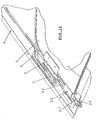
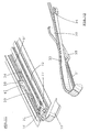
- FIGs. 11 - 15 show a wind deflector as used in the open roof construction according to the invention.
- FIG. 11 there is shown a part of the fixed roof construction of a vehicle comprising a guide 32.
- a wind deflector 33 is pivotally connected to the fixed roof construction 31 at the location of a pivot point 34.
- Wind deflector 33 comprises a leaf spring 33 at its bottom side (see Fig. 12), which engages the fixed roof construction 31 and which loads the wind deflector 33 in upward direction.
- a roller 36 which is accommodated in a slide 37 which moves in guide 32, impedes the upward movement of the wind deflector 33, however.
- Slide 37 is connected to a closing panel (not shown), for example, in such a manner that the slide 37 will move to the right, seen in Fig.
- the wind deflector mechanism furthermore comprises a drivable curved member 38, which can likewise move forward and backward with respect to the fixed roof construction 31 (parallel to slide 37). Said movement of the curved member 38 can be arranged by driving element 5.
- driving element 5 Referring to Fig. 1, it is for example possible that the end of the driving element (not shown) that is located on the right in said figure makes contact with the curved member 38 when closure elements 3 and 4 are moved to the right to a position in which they release the roof opening 1 (as is for example shown in Fig. 10), in which position it is desirable for the wind deflector 33 to be driven additionally (as will be described yet hereafter).
- Curved member 38 comprises a first curved portion 39 on its upper side, which can mate with the end of leaf spring 35. This makes it possible to adjust the spring load that is exerted by leaf spring 35. Curved member 38 furthermore comprises a downwardly extending, second curved portion 40, which mates with a cam 41 disposed on wind deflector 33 (which cam is only shown in the bottom plan view of Fig. 15). When roller 36 is no longer in contact with the wind deflector 33, said cam 41 determines the pivoting angle of the wind deflector 33.
- the pivoting angle of the wind deflector 33 is determined by the position of slide 37 during the time roller 36 is in contact with the wind deflector 33. Once the slide 37 has been moved so far that roller 36 is no longer in contact with the wind deflector 33, the pivoting angle of the wind deflector 33 is determined, as already said before, by the mating relationship between the cam 41 thereof and the curved portion 40 of the curved member 38. The mating relationship between the leaf spring 35 and the curved portion 39 of curved member 38 thereby determines the spring load that is exerted on wind deflector 33, or, in other words, the force that is required to push the wind deflector 33 down.
- connection between curved member 38 and the driving element 5 can be effected by means of a spring member, so that curved member 38 can be moved against the force of the spring of said spring member for the purpose of demounting the wind deflector 33.
- numeral 5' in Figs. 11 - 15 indicates a guide for driving element 5 (which driving element itself is not shown therein).
Landscapes
- Engineering & Computer Science (AREA)
- Mechanical Engineering (AREA)
- Power-Operated Mechanisms For Wings (AREA)
- Lock And Its Accessories (AREA)
Abstract
Description
- The invention relates to an open roof construction for a vehicle, comprising a roof opening formed in the roof of the vehicle and at least one closure element, which is movable along a guide between a position in which it closes the roof opening and a position in which it releases the roof opening, wherein a driving mechanism is used for the closure element, which driving mechanism comprises a driving source and at least one driving element which couples said driving source to said closure element, which closure element can be locked in at least one position with respect to said guide, whilst the driving element can be disconnected from said closure element in said position and be moved with respect thereto for the purpose of driving another element that forms part of the open roof construction.
- Examples of prior art open roof constructions of this type are to be found in, for example, German Offenlegungsschrift nos. 3424334 and 19654558 and in US patent no. 4,974,902.
- It is an object of the present invention to further improve an open roof construction of the present type.
- In order to accomplish that objective, the open roof construction according to the invention is characterized in that a coupling arm is present between said closure element and said driving element, which coupling arm is pivotally connected to said closure element with one end and which engages said driving element with its other end, in such a manner that the coupling arm, in a first pivoted position thereof, is substantially rigidly connected to the driving element, whilst in a second pivoted position of the coupling arm the closure element is on the one hand fixed in position with respect to said guide, whilst on the other hand the driving element becomes movable with respect to the coupling arm and the closure element.
- In this way an effective, reliable construction is provided, by means of which the driving element is given an additional driving function.
- It is noted that a variant wherein the coupling arm is pivotally connected to the driving element with one end and engages the closure element with its other end merely constitutes a kinematic reversal and consequently falls within the scope of the present invention as well.
- In an advantageous embodiment of the open roof construction according to the invention, the selective movability of the coupling arm with respect to the driving element is effected in that the driving element includes a slide provided with an elongated groove, in which a slide block which is connected to the coupling arm is accommodated, wherein the groove and the slide block are so designed that movement of the slide block within said groove is not possible in the first pivoted position of the coupling arm, whereas such movement is possible indeed in the second pivoted position.
- The coupling arm can be moved to its first and its second pivoted position in an advantageous manner in that the coupling arm carries a locking projection, which is moved through said guide for the purpose of defining said first pivoted position, and which is capable of engaging in a locking recess in the fixed roof construction of the vehicle, for example in said guide, in said second pivoted position so as to fix the closure element with respect to the guide, wherein the groove of said slide comprises a straight first portion having straight walls, which extends substantially parallel to said guide, and an adjoining second portion having sloping walls, which includes an angle with said straight portion, wherein the slide block, which is diamond-shaped, is present in said second groove portion in the first pivoted position of the coupling arm, being rigidly connected to the slide by the sloping walls thereof, and wherein said slide block is positioned in said first groove portion in said second pivoted position, in which position it is capable of movement between the straight walls thereof.
- When the locking projection of the coupling arm is being moved through the guide, the slide block is positioned in the second groove portion, therefore. In this position the driving force that is exerted by the driving element can be transmitted to the slide block via the sloping walls, and consequently to the closure element via the coupling arm. In this manner the driving element is connected to the closure element.
- The sloping groove walls exert a force component on the diamond-shaped slide block, which attempts to move the slide block out of the second groove portion. The co-operation between the locking projection and the guide prevents such movement of the slide block and the resulting pivoting movement of the coupling arm, however. When the locking projection reaches the aforesaid locking recess in the fixed roof construction, for example in the guide, however, said force component will cause the slide block to move, whereby the locking projection will engage in said locking recess. On the one hand this will cause the coupling arm, and thus also the closure element, to be fixed in position with respect to the fixed roof construction. In addition, however, the slide block will move from the second groove portion to the first groove portion, thus enabling the slide to move with respect to the slide block. The slide block thus moves into the first groove portion.
- Hereinbefore it has been described how the closure element can be locked in at least one position, whilst the driving element can be disconnected from the closure element in that position. It is also possible, however, to achieve a comparable effect in yet another position of the closure element. In such a case the coupling arm can also take up a third pivoted position, in which movement of the driving element with respect to the coupling arm and the closure element becomes possible, and in which position the direction of the movement of the driving element on the one hand and the coupling arm and the closure element on the other hand with respect to each other is opposed to the direction of the relative movement of said parts in the second pivoted position.
- This can be effected, for example, in that the groove comprises two straight groove portions adjoining the second groove portion on opposite sides thereof, wherein the slide block of the coupling arm is present in one straight groove portion in its second pivoted position, whilst it is present in the other straight groove portion in its third pivoted position. Preferably, the coupling arm will furthermore carry a second locking projection in such a case, which mates with an additional locking recess in the fixed roof construction in an similar manner.
- In a practical embodiment of the open roof construction according to the invention, a second closure element is used, which can be driven together with the first closure element by the driving element, and which, in the position in which the first closure element is locked in position with respect to the guide, can be moved with respect to the first closure element by the driving element, which is likewise movable with respect to the first closure element in that position. Thus the two closure elements may first be moved to the position in which they close the roof opening, for example, after which the second closure element is moved back slightly with respect to the first closure element, in order to form an opening between the two closure elements, for example for the purpose of obtaining pressure equalization.
- Such a manner of driving the second closure element with respect to the first closure element can be effected, for example, when the driving element is returned to said second closure element, to which it is connected, in a looped path through said first closure element. As long as the coupling arm is in its first pivoted position and the driving element is connected to said first closure element, the driving element and the first closure element will not move with respect to each other, and neither will the first and the second closure element, therefore. When the coupling arm has left its first pivoted position and the driving element is capable of movement with respect to the first closure element, however, said movement is returned to the second closure element in reverse direction via the looped portion of the driving element, which second closure element will subsequently move in a direction opposed to the original direction of movement of the first closure element so as to space the two closure elements apart.
- As already briefly indicated before, said one position may be the position in which the closure element closes the roof opening.
- When, as already said before, a second closure element is used, it is advantageous to use an embodiment of the open roof construction wherein the second closure element can be moved from the closing position to the releasing position along the same guide as the first closure element, wherein lateral guides connect to said guides, into which the second closure element can be moved to its releasing position so as to place the two closure elements in an overlapping position adjacently to each other, and wherein the second closure element is connected to the driving element in such a manner that when said second closure element is accommodated in said lateral guides, the driving element can move with respect to the second closure element.
- Initially, the two closure elements move from the closing position to the releasing position. Then the second closure element moves into the lateral guides and remains stationary therein. The first closure element then continues its movement beside the second closure element. Once the second closure element has arrived in the lateral guides, the driving element is disconnected from said second closure element.
- Said disconnection can be effected, for example, in that the driving element engages in a channel formed in the second closure element by means of a connecting arm, in such a manner that when the second closure element is positioned in the lateral guides, said connecting arm will move through said channel upon movement of the first closure element to the position in which it overlaps the second closure element, and wherein said connecting arm strikes against a channel end upon movement of the first closure element in the opposite direction, thus carrying the second closure element along with the first closure element.
- During the movement of the two closure elements from the closing position to the releasing position, the movement of the connecting arm in the channel makes it possible for the first closure element to continue its movement beside the second closure element once the second closure element has reached the lateral guides. In this manner an overlapping, compact position of the two closure elements is effected. In reverse direction, during movement from said releasing position to said closing position, the second closure element will initially remain stationary until the connecting arm strikes against the channel end in question and the second closure element is pulled out of the lateral guides into the guide, from where it will move along with the first closure element to the closing position.
- The movement of the second closure element in the lateral guides can be effected in that the lateral guides are formed by two inclined recesses of different length, whilst the second closure element is fitted with two correspondingly dimensioned guide shoes, wherein said recesses and said guide shoes are so positioned that during movement of the second closure element to the releasing position, the longer guide shoes first pass the shorter recesses before the longer guide shoes reach the longer recesses and the shorter guide shoes reach the shorter recesses.
- Said closure element (or elements) may be a sun screen, for example.
- The invention furthermore relates to an open roof construction of the present type, comprising a wind deflector which is pivotable between an inoperative position, in which it lies substantially in the plane of the roof, and an operative position, in which it slopes upwards from said plane, which wind deflector is spring-loaded to the operative position, and which engages, at least in its operative position, a stop which can be moved by the movement of the closure element. In accordance with the invention, this open roof construction comprises a curved member which can be driven by the driving element, a first curved portion of which mates with a spring member providing said spring load, and a second curved portion of which mates with a cam disposed on the wind deflector, which determines the pivoting angle that is caused by the spring load.
- In principle the movable stop determines the pivoted position of the wind deflector, as is well-known. Once the stop has been moved, however, the cam that is disposed on the wind deflector will mate with the second curved portion of the curved member. The spring member that mates with the first curved portion also determines the spring load that is exerted on the wind deflector. Said spring load can be adjusted by suitably moving the curved member, therefore, it can for example be increased at high vehicle speeds. Nevertheless, it remains possible to pivot the wind deflector back against said spring load towards its inoperative position. The cam is moved clear of the second curved portion thereby. In other words, the spring member urges the cam against the second curved portion in such a situation.
- Finally it is possible for the connection between the driving element and the curved member to comprise a spring member. In this way the curved member can be moved against the force of said spring member with respect to the driving element, which may be advantageous when the wind deflector is to be removed or maintenance work is to be carried out.
- The invention will now be explained in more detail with reference to the drawing, which shows a few embodiments of the open roof construction according to the invention. In the drawing:
- Fig. 1 is a perspective overview of an embodiment of the open roof construction according to the invention, showing the closed position thereof;
- Fig. 2 is a perspective, larger-scale view of the connection between a driving element and a ce;
- Fig. 3 is a view from another direction of the connection of Fig. 2, wherein the connection is shown in a first position thereof;
- Fig. 4 is a view corresponding to Fig. 3, wherein the connection is shown in a second position thereof;
- Fig. 5 shows a detail of the open roof construction comprising a locking projection;
- Fig. 6 likewise shows a detail of the open roof construction comprising a locking projection;
- Fig. 7 is a perspective view of a part of the open roof construction comprising lateral guides;
- Fig. 8 is a larger-scale, detail view of a lateral guide according to Fig. 7;
- Fig. 9 shows a connecting arm present between two closure elements;
- Fig. 10 shows two overlapping closure elements of the open roof construction according to the invention;
- Fig. 11 is a perspective overview of an operating mechanism for a wind deflector used in the open roof construction according to the invention;
- Fig. 12 shows a few individual parts of the operating mechanism of Fig. 11;
- Fig. 13 shows the operating mechanism of Fig. 11 in another position thereof;
- Fig. 14 shows the operating mechanism of Fig. 11 in yet another position thereof; and
- Fig. 15 is a bottom plan view of a part of the operating mechanism of Fig. 11.
-
- Referring to Fig. 1, there is shown a part of an open roof construction for a vehicle. A roof opening 1 is formed in the roof (not shown) of a vehicle in a well-known manner. Said roof opening 1 is flanked by two
guides 2 that form part of the fixed roof construction (only one of which is shown in Fig. 1). Two closure elements, viz. afront closure element 3 and arear closure element 4, are movable alongguides 2 by means of suitable guide elements (not shown in detail) in the illustrated embodiment. In order to effect said movement, a driving mechanism is used which, as is known per se for this type of open roof constructions, employs a driving element 5 (indicated by a dotted line in Fig. 1), which is connected to a driving source (not shown), for example an electric motor or a hand crank. Drivingelement 5 preferably consists of a pull-push cable. - In the illustrated embodiment, said
closure elements closure elements - As clearly appears in particular from Figs. 2 - 4, driving
element 5 includes a slide 6 (in this embodiment said slide is fixedly connected to the pull-push cable).Slide 6 is coupled, by means of acoupling arm 7, to anextension 8 connected to thefront closure element 3.coupling arm 7 is pivotally connected to thefront closure element 3 with one end, and it engagesslide 6 with its other end. - The co-operation between
coupling arm 7 and slide 6 can best be illustrated with reference to Figs. 3 and 4.Slide 6 includes anelongated groove 9, which accommodates aslide block 10 that is connected to the respective end of thecoupling arm 7. In the illustrated embodiment,groove 9 comprises a straightfirst groove portion 11 havingstraight walls 12, which extends substantially parallel to guide 2, and an adjoiningsecond groove portion 13 having slopingwalls 14, which includes an angle with saidstraight groove portion 11, and athird groove portion 15 havingstraight walls 16, wherein the slide block, which is diamond-shaped, is present in said second groove portion in the first pivoted position of the coupling arm, being rigidly connected to the slide by the sloping walls thereof, and wherein said slide block is present in said first groove portion in the second pivoted position, being capable of movement between the straight walls thereof. -
Slide block 10 ofcoupling arm 7 is diamond-shaped to match the shape of thesloping groove portion 13 having slopingwalls 14. Furthermore, a lockingprojection 17 is disposed besideslide block 10 on the end ofcoupling arm 7 in question. - During movement of the
front closure element 3 alongguide 2, lockingprojection 17 engages the inside ofguide 2. This causes thecoupling arm 7 to take up the position that is shown in Fig. 3, wherein theslide block 14 is present in thesloping slot portion 13, engaging the slopinggroove walls 14 with two sides of its diamond shape. In this way, a force being exerted by drivingelement 5 is transmitted to the diamond-shaped slide block, and consequently to thecoupling arm 7, by the slopinggroove walls 14, and, via theextension 8, to thefront closure element 3, which can thus be moved inguide 2. - Although a force component directed perpendicularly to the longitudinal direction of
guide 2 is exerted onslide block 10 as well, due to the inclined position of the slopinggroove walls 14, which force component attempts to moveslide block 10 out of thesloping groove portion 13 in the direction of one of thestraight groove portions 11 or 15 (depending on the direction of the force being exerted by the driving element 5), such movement is prevented, as already said before, in that lockingprojection 17 is retained inguide 2. - Reference is now made to Figs. 5 and 6. A locking
recess 18 is formed inguide 2. Whenslide 6, in which theslide block 10 is present, reaches said lockingrecess 18, said slide block can move along the slopinggroove walls 14 under the influence of the aforesaid force component, whereby lockingprojection 17 falls into said lockingrecess 18. As a result,coupling arm 7, and consequently thefront closure element 3, is fixed in position with respect to guide 2 (and consequently with respect to the fixed roof construction). On the other hand, however,slide block 10 has moved out of thesloping groove portion 13 into (in this example) thestraight groove portion 11, so that a force that is exerted onslide 6 by the drivingelement 5 can no longer be transmitted to slideblock 10, since theslide block 10 will move within thestraight slot portion 11. This means that theclosure element 3 and thecoupling arm 7 remains stationary, whilstslide 6 continues its movement. - It is noted that the other
straight groove portion 15 can be used in a corresponding manner when the lockingprojection 17 falls into another locking recess (not shown) that is disposed on an opposite side ofguide 2. - Referring back to Fig. 1, a looped
guide 19 for drivingelement 5 is shown to be formed in thefront closure element 3. In this way the drivingelement 5 is returned in a looped path through thefront closure element 3 to therear closure element 4, to which it is connected by means of a connectingelement 20 yet to be described in more detail (also refer to Fig. 2 and Fig. 6). - The operation is as follows: when the
front closure element 3 and therear closure element 4 are moved from an position (not shown) in which they release the roof opening to a position in which they close said roof opening 1, thecoupling arm 7 initially takes up in the position that is shown in Fig. 3. In this position the driving element is rigidly connected to thefront closure element 3 in the previously described manner. In that situation therear closure element 4 also occupies a fixed position with respect to thefront closure element 3 via the loopedguide 19 and the connectingelement 20. - Once it has reached the
locking recess 18, thecoupling arm 7 moves to the position that is shown in Fig. 4, thus locking thefront closure element 3 in position, whilstslide 6, which is driven by drivingelement 5, continues its movement. Via the loopedguide 19, said continued movement of the drivingelement 5 is transmitted to connectingelement 20, as a result of which therear closure element 4 moves back (to the right in Fig. 1), so that a gap 21 (Fig. 6) is formed between thefront closure element 3 and therear closure element 4. Such a gap may be of importance with a view to obtaining pressure equalization between the interior of the vehicle and the outside atmosphere. In reverse direction, therear closure element 4 is moved to the left from the position that is shown in Fig. 6, until it abuts against thefront closure element 3. By that time theslide block 10 that is present in thestraight groove portion 11 will have moved so far that the sloping sides of theslide block 10 start to mate with the slopinggroove walls 14, as a result of which a force component is exerted onslide block 10, which causes the slide block to be moved out of lockingrecess 18 and into the slopinggroove portion 13. As a result, thefront closure element 3 is disconnected from the fixed roof construction and fixedly connected to the drivingelement 5, after which the assembly consisting offront closure element 3 andrear closure element 4 moves ahead in the direction of the position in which they release the roof opening (to the right in Fig. 1). - Reference is now made to Figs. 7 - 10 for a discussion of another aspect of the open roof construction according to the invention. It is noted thereby that Figs. 7, 8 and 10 show the construction from a different side in comparison with the preceding figures. Thus, the
rear closure element 4 is shown on the left in Fig. 7, whilst thefront closure element 3 is shown on the right. - Each
guide 2 has twolateral guides Lateral guide 22 is shorter in length than the otherlateral guide 23, seen in the longitudinal direction ofguide 2.Rear closure element 4 comprises guideshoes longer guide shoe 24 of which is shown on a larger scale in Fig. 8 (in this figure, therear closure element 4 is not shown for the sake of clarity). Lateral guides 22 and 23 are in the form of inclined recesses, whilst guide shoes 24 and 25 have a corresponding, diamond-shaped contour. When thelong guide shoe 24 passes theshort lateral guide 22, it cannot be received in said lateral guide. When thelong guide shoe 24 reaches thelong lateral guide 23, however, said guide shoe will move into said lateral guide. At the same time, theshort guide shoe 25 will move into theshort lateral guide 22 that corresponds thereto. Generally, such a movement will take place under the influence of the force of gravity, but it is also possible hat additional provisions have been made to ensure that the guide shoes will correctly move into the lateral guides (for example in extreme conditions, in which strong vibrations develop in the vehicle). - The object of accommodating the
rear closure element 4 in the lateral guides 22 and 23 is to enable thefront closure element 3 to move over therear closure element 4 to a position in which in overlaps saidclosure element 4. In this manner the closure elements take up a compact position, in which they occupy little space, in the position in which they release the roof opening. - Now an additional function of the connecting
element 20, by means of which thedriving element 5 engages the rear closure element 4 (after being returned in a looped path), becomes apparent. In this connection reference is made in particular to Fig. 9, which is a perspective rear view, seen from the perspective of Figs. 7 and 8. Connectingelement 20 consists of a connectingblock 26, in which a connectingarm 27 is pivotally accommodated. The end of said connectingarm 27 engages with acam 28 in achannel 29, which is formed in therear closure element 4. - When the
rear closure element 4 is accommodated in lateral guides 22 and 23 with itsguide shoes front closure element 3 can move to the right (seen in Fig. 9) over saidrear closure element 4, wherebycam 28 moves withinchannel 29. In this way theclosure elements cam 28 initially moves to the left (seen in Fig. 9) inchannel 29, and finally it strikes against a channel end 30 (see Fig. 9). As a result, therear closure element 4 is pulled out of the lateral guides 22 and 23 in the form of inclined recesses inguide 2, after which saidrear closure element 4 moves further together with thefront closure element 3. - Finally, reference is made to Figs. 11 - 15, which show a wind deflector as used in the open roof construction according to the invention.
- Referring to Fig. 11, there is shown a part of the fixed roof construction of a vehicle comprising a
guide 32. Awind deflector 33 is pivotally connected to the fixedroof construction 31 at the location of apivot point 34.Wind deflector 33 comprises aleaf spring 33 at its bottom side (see Fig. 12), which engages the fixedroof construction 31 and which loads thewind deflector 33 in upward direction. Aroller 36, which is accommodated in aslide 37 which moves inguide 32, impedes the upward movement of thewind deflector 33, however.Slide 37 is connected to a closing panel (not shown), for example, in such a manner that theslide 37 will move to the right, seen in Fig. 11, when said closing panel is moved to a position in which it releases the roof opening, allowing thewind deflector 33 to pivot upwards under the influence of the spring force fromleaf spring 35. Such a situation is shown in Fig. 13 (which is a perspective view from the opposite side). - The wind deflector mechanism furthermore comprises a drivable
curved member 38, which can likewise move forward and backward with respect to the fixed roof construction 31 (parallel to slide 37). Said movement of thecurved member 38 can be arranged by drivingelement 5. Referring to Fig. 1, it is for example possible that the end of the driving element (not shown) that is located on the right in said figure makes contact with thecurved member 38 whenclosure elements wind deflector 33 to be driven additionally (as will be described yet hereafter). -
Curved member 38 comprises a firstcurved portion 39 on its upper side, which can mate with the end ofleaf spring 35. This makes it possible to adjust the spring load that is exerted byleaf spring 35.Curved member 38 furthermore comprises a downwardly extending, secondcurved portion 40, which mates with acam 41 disposed on wind deflector 33 (which cam is only shown in the bottom plan view of Fig. 15). Whenroller 36 is no longer in contact with thewind deflector 33, saidcam 41 determines the pivoting angle of thewind deflector 33. - The pivoting angle of the
wind deflector 33 is determined by the position ofslide 37 during thetime roller 36 is in contact with thewind deflector 33. Once theslide 37 has been moved so far thatroller 36 is no longer in contact with thewind deflector 33, the pivoting angle of thewind deflector 33 is determined, as already said before, by the mating relationship between thecam 41 thereof and thecurved portion 40 of thecurved member 38. The mating relationship between theleaf spring 35 and thecurved portion 39 ofcurved member 38 thereby determines the spring load that is exerted onwind deflector 33, or, in other words, the force that is required to push thewind deflector 33 down. - The connection between
curved member 38 and the drivingelement 5 can be effected by means of a spring member, so thatcurved member 38 can be moved against the force of the spring of said spring member for the purpose of demounting thewind deflector 33. - Finally it is noted that numeral 5' in Figs. 11 - 15 indicates a guide for driving element 5 (which driving element itself is not shown therein).
- The invention is not restricted to the embodiments as described above, which can be varied in several ways without departing from the scope of the invention as defined in the claims.
Claims (19)
- An open roof construction for a vehicle, comprising a roof opening formed in the roof of the vehicle and at least one closure element, which is movable along a guide between a position in which it closes the roof opening and a position in which it releases the roof opening, wherein a driving mechanism is used for the closure element, which driving mechanism comprises a driving source and at least one driving element which couples said driving source to said closure element, which closure element can be locked in at least one position with respect to said guide, whilst the driving element can be disconnected from said closure element in said position and be moved with respect thereto for the purpose of driving another element that forms part of the open roof construction, characterized in that a coupling arm is present between said closure element and said driving element, which coupling arm is pivotally connected to said closure element with one end and which engages said driving element with its other end, in such a manner that the coupling arm, in a first pivoted position thereof, is substantially rigidly connected to the driving element, whilst in a second pivoted position of the coupling arm the closure element is on the one hand fixed in position with respect to said guide, whilst on the other hand the driving element becomes movable with respect to the coupling arm and the closure element.
- An open roof construction according to claim 1, characterized in that said driving element includes a slide provided with an elongated groove, in which a slide block which is connected to the coupling arm is accommodated, wherein the groove and the slide block are so designed that movement of the slide block within said groove is not possible in the first pivoted position of the coupling arm, whereas such movement is possible indeed in the second pivoted position.
- An open roof construction according to claim 2, characterized in that the coupling arm carries a locking projection, which is moved through said guide for the purpose of defining said first pivoted position, and which is capable of engaging in a locking recess in the fixed roof construction of the vehicle, for example in said guide, in said second pivoted position so as to fix the closure element with respect to the guide, wherein the groove of said slide comprises a straight first portion having straight walls, which extends substantially parallel to said guide, and an adjoining second portion having sloping walls, which includes an angle with said straight portion, wherein the slide block, which is diamond-shaped, is present in said second groove portion in the first pivoted position of the coupling arm, being rigidly connected to the slide by the sloping walls thereof, and wherein said slide block is positioned in said first groove portion in said second pivoted position, in which position it is capable of movement between the straight walls thereof.
- An open roof construction according to any one of the claims 1 - 3, characterized in that the coupling arm can also take up a third pivoted position, in which movement of the driving element with respect to the coupling arm and the closure element becomes possible, and in which position the direction of the movement of the driving element on the one hand and the coupling arm and the closure element on the other hand with respect to each other is opposed to the direction of the relative movement of said parts in the second pivoted position.
- An open roof construction according to claim 3 and 4, characterized in that the groove comprises two straight groove portions adjoining the second groove portion on opposite sides thereof, wherein the slide block of the coupling arm is present in one straight groove portion in its second pivoted position, whilst it is present in the other straight groove portion in its third pivoted position.
- An open roof construction according to claim 5, characterized in that the coupling arm furthermore carries a second locking projection.
- An open roof construction according to any one of the preceding claims, characterized in that a second closure element is used, which can be driven together with the first closure element by the driving element, and which, in the position in which the first closure element is locked in position with respect to the guide, can be moved with respect to the first closure element by the driving element, which is likewise movable with respect to the first closure element in that position.
- An open roof construction according to claim 7, characterized in that the driving element is returned to said second closure element, to which it is connected, in a looped path through said first closure element.
- An open roof construction according to any one of the preceding claims, characterized in that said one position is the position in which the closure element closes the roof opening.
- An open roof construction according to claim 7, 8 or 9, characterized in that the second closure element can be moved from the closing position to the releasing position along the same guide as the first closure element, wherein lateral guides connect to said guides, into which the second closure element can be moved to its releasing position so as to place the two closure elements in an overlapping position adjacently to each other, and wherein the second closure element is connected to the driving element in such a manner that when said second closure element is accommodated in said lateral guides, the driving element can move with respect to the second closure element.
- An open roof construction according to claim 10, characterized in that the driving element engages in a channel formed in the second closure element by means of a connecting arm, in such a manner that when the second closure element is positioned in the lateral guides, said connecting arm will move through said channel upon movement of the first closure element to the position in which it overlaps the second closure element, and wherein said connecting arm strikes against a channel end upon movement of the first closure element in the opposite direction, thus carrying the second closure element along with the first closure element.
- An open roof construction according to claim 10 or 11, characterized in that said lateral guides are formed by two inclined recesses of different length, whilst the second closure element is fitted with two correspondingly dimensioned guide shoes, wherein said recesses and said guide shoes are so positioned that during movement of the second closure element to the releasing position, the longer guide shoes first pass the shorter recesses before the longer guide shoes reach the longer recesses and the shorter guide shoes reach the shorter recesses.
- An open roof construction according to any one of the preceding claims, characterized in that said closure element is a sun screen.
- An open roof construction according to any one of the preceding claims, comprising a wind deflector which is pivotable between an inoperative position, in which it lies substantially in the plane of the roof, and an operative position, in which it slopes upwards from said plane, which wind deflector is spring-loaded to the operative position, and which engages, at least in its operative position, a stop which can be moved by the movement of the closure element, characterized by a curved member which can be driven by the driving element, a first curved portion of which mates with a spring member providing said spring load, and a second curved portion of which mates with a cam disposed on the wind deflector, which determines the pivoting angle that is caused by the spring load.
- An open roof construction according to claim 14, characterized in that the connection between said driving element and said curved member comprises a spring member.
- An open roof construction for a vehicle, comprising a roof opening formed in the roof of the vehicle and at least two closure elements, which are movable along a guide between a position in which they close the roof opening and a position in which they release the roof opening, characterized in that the two closure elements can be moved from the closing position to the releasing position along the same guide as the first closure element, wherein lateral guides connect to said guides, into which one of the closure elements can be moved to its releasing position so as to place the two closure elements in an overlapping position adjacently to each other, and wherein the closure element in question is connected to the driving element in such a manner that when said closure element is accommodated in said lateral guides, the driving element can move with respect to said closure element.
- An open roof construction according to claim 16, characterized in that the driving element engages in a channel formed in the second closure element by means of a connecting arm, in such a manner that when the second closure element is positioned in the lateral guides, said connecting arm will move through said channel upon movement of the first closure element to the position in which it overlaps the second closure element, and wherein said connecting arm strikes against a channel end upon movement of the first closure element in the opposite direction, thus carrying the second closure element along with the first closure element.
- An open roof construction according to claim 16 or 17, characterized in that said lateral guides are formed by two inclined recesses of different length, whilst the second closure element is fitted with two correspondingly dimensioned guide shoes, wherein said recesses and said guide shoes are so positioned that during movement of the second closure element to the releasing position, the longer guide shoes first pass the shorter recesses before the longer guide shoes reach the longer recesses and the shorter guide shoes reach the shorter recesses.
- An open roof construction for a vehicle, comprising a roof opening formed in the roof of the vehicle and at least one closure element, which is movable along a guide between a position in which it closes the roof opening and a position in which it releases the roof opening, wherein a driving mechanism is used for the closure element, which driving mechanism comprises a driving source and at least one driving element which couples said driving source to said closure element, furthermore comprising a wind deflector which is pivotable between an inoperative position, in which it lies substantially in the plane of the roof, and an operative position, in which it slopes upwards from said plane, which wind deflector is spring-loaded to the operative position, and which engages, at least in its operative position, a stop which can be moved by the movement of the closure element, characterized by a curved member which can be driven by the driving element, a first curved portion of which mates with a spring member providing said spring load, and a second curved portion of which mates with a cam disposed on the wind deflector, which determines the pivoting angle that is caused by the spring load.
Priority Applications (5)
| Application Number | Priority Date | Filing Date | Title |
|---|---|---|---|
| DE60143862T DE60143862D1 (en) | 2001-04-03 | 2001-04-03 | Open roof construction for a vehicle |
| EP01201206A EP1247674B1 (en) | 2001-04-03 | 2001-04-03 | Open roof construction for a vehicle |
| EP08156416A EP1964702B1 (en) | 2001-04-03 | 2001-04-03 | Open roof construction for a vehicle |
| DE60134119T DE60134119D1 (en) | 2001-04-03 | 2001-04-03 | Construction of an openable vehicle roof |
| US10/115,586 US6652023B2 (en) | 2001-04-03 | 2002-04-03 | Open roof construction for a vehicle |
Applications Claiming Priority (1)
| Application Number | Priority Date | Filing Date | Title |
|---|---|---|---|
| EP01201206A EP1247674B1 (en) | 2001-04-03 | 2001-04-03 | Open roof construction for a vehicle |
Related Child Applications (1)
| Application Number | Title | Priority Date | Filing Date |
|---|---|---|---|
| EP08156416A Division EP1964702B1 (en) | 2001-04-03 | 2001-04-03 | Open roof construction for a vehicle |
Publications (2)
| Publication Number | Publication Date |
|---|---|
| EP1247674A1 true EP1247674A1 (en) | 2002-10-09 |
| EP1247674B1 EP1247674B1 (en) | 2008-05-21 |
Family
ID=8180094
Family Applications (2)
| Application Number | Title | Priority Date | Filing Date |
|---|---|---|---|
| EP01201206A Expired - Lifetime EP1247674B1 (en) | 2001-04-03 | 2001-04-03 | Open roof construction for a vehicle |
| EP08156416A Expired - Lifetime EP1964702B1 (en) | 2001-04-03 | 2001-04-03 | Open roof construction for a vehicle |
Family Applications After (1)
| Application Number | Title | Priority Date | Filing Date |
|---|---|---|---|
| EP08156416A Expired - Lifetime EP1964702B1 (en) | 2001-04-03 | 2001-04-03 | Open roof construction for a vehicle |
Country Status (3)
| Country | Link |
|---|---|
| US (1) | US6652023B2 (en) |
| EP (2) | EP1247674B1 (en) |
| DE (2) | DE60134119D1 (en) |
Cited By (2)
| Publication number | Priority date | Publication date | Assignee | Title |
|---|---|---|---|---|
| EP1650069A1 (en) | 2004-10-25 | 2006-04-26 | Inalfa Roof Systems Group B.V. | Open roof construction |
| EP1985484A1 (en) * | 2007-04-24 | 2008-10-29 | Webasto AG | Actuating device for actuating a wind deflector device |
Families Citing this family (4)
| Publication number | Priority date | Publication date | Assignee | Title |
|---|---|---|---|---|
| DE102004050811A1 (en) * | 2004-10-19 | 2006-04-20 | Arvinmeritor Gmbh | Cover for a sunroof system |
| US7320499B2 (en) * | 2005-10-27 | 2008-01-22 | Specialty Vehicle Acquisition Corp. | Movable roof drive system |
| AT513942B1 (en) * | 2013-01-22 | 2017-11-15 | Htp High Tech Plastics Gmbh | Device for covering a viewing opening |
| KR102673008B1 (en) * | 2019-05-21 | 2024-06-05 | 현대자동차주식회사 | Roof vent |
Citations (6)
| Publication number | Priority date | Publication date | Assignee | Title |
|---|---|---|---|---|
| GB2090630A (en) * | 1980-11-28 | 1982-07-14 | Vermeulen Hollandia Octrooien | Sliding roof for vehicle |
| DE3424334A1 (en) | 1984-07-02 | 1986-01-09 | Karosseriewerke Weinsberg Gmbh, 7102 Weinsberg | Tiltable sliding roof for a motor vehicle |
| EP0321003A1 (en) * | 1987-12-16 | 1989-06-21 | Vermeulen-Hollandia Octrooien II B.V. | Coupling device in the drive mechanism for a movable panel of an open roof-construction for a vehicle |
| DE19654558A1 (en) | 1995-12-28 | 1997-11-06 | Aisin Seiki | Sliding roof appts for passenger cars |
| US6129413A (en) * | 1997-11-13 | 2000-10-10 | Asc Incorporated | Powered dual panel sunroof |
| DE19941984C1 (en) * | 1999-09-03 | 2000-10-19 | Porsche Ag | Multi-part sliding roof for a cross country vehicle sunroof has sections with independent movements to be set in a variety of configurations and is flush with the roof when closed without projecting guides |
Family Cites Families (5)
| Publication number | Priority date | Publication date | Assignee | Title |
|---|---|---|---|---|
| DE4129860C1 (en) * | 1991-09-07 | 1992-09-17 | Webasto Ag Fahrzeugtechnik, 8035 Stockdorf, De | |
| DE4330426A1 (en) * | 1993-09-08 | 1995-03-09 | Hs Tech & Design | Device for guiding a vehicle sunroof cover |
| KR100200965B1 (en) | 1995-12-30 | 1999-06-15 | 윤종용 | A second cassette feeder using electrographic method |
| JP3510958B2 (en) * | 1996-08-30 | 2004-03-29 | 株式会社大井製作所 | Sunroof equipment |
| EP0863817B1 (en) * | 1996-10-01 | 2003-07-30 | WEBASTO KAROSSERIESYSTEME GmbH | Vehicle roof with at least one cover |
-
2001
- 2001-04-03 DE DE60134119T patent/DE60134119D1/en not_active Expired - Lifetime
- 2001-04-03 EP EP01201206A patent/EP1247674B1/en not_active Expired - Lifetime
- 2001-04-03 EP EP08156416A patent/EP1964702B1/en not_active Expired - Lifetime
- 2001-04-03 DE DE60143862T patent/DE60143862D1/en not_active Expired - Lifetime
-
2002
- 2002-04-03 US US10/115,586 patent/US6652023B2/en not_active Expired - Lifetime
Patent Citations (8)
| Publication number | Priority date | Publication date | Assignee | Title |
|---|---|---|---|---|
| GB2090630A (en) * | 1980-11-28 | 1982-07-14 | Vermeulen Hollandia Octrooien | Sliding roof for vehicle |
| DE3424334A1 (en) | 1984-07-02 | 1986-01-09 | Karosseriewerke Weinsberg Gmbh, 7102 Weinsberg | Tiltable sliding roof for a motor vehicle |
| EP0321003A1 (en) * | 1987-12-16 | 1989-06-21 | Vermeulen-Hollandia Octrooien II B.V. | Coupling device in the drive mechanism for a movable panel of an open roof-construction for a vehicle |
| US4974902A (en) | 1987-12-16 | 1990-12-04 | Vermeulen-Hollandia Octrooien Ii B.V. | Coupling device in the drive mechanism for a movable panel of an open roof construction for a vehicle |
| DE19654558A1 (en) | 1995-12-28 | 1997-11-06 | Aisin Seiki | Sliding roof appts for passenger cars |
| US5899524A (en) * | 1995-12-28 | 1999-05-04 | Aisin Seiki Kabushiki Kaisha | Sliding roof assembly |
| US6129413A (en) * | 1997-11-13 | 2000-10-10 | Asc Incorporated | Powered dual panel sunroof |
| DE19941984C1 (en) * | 1999-09-03 | 2000-10-19 | Porsche Ag | Multi-part sliding roof for a cross country vehicle sunroof has sections with independent movements to be set in a variety of configurations and is flush with the roof when closed without projecting guides |
Cited By (2)
| Publication number | Priority date | Publication date | Assignee | Title |
|---|---|---|---|---|
| EP1650069A1 (en) | 2004-10-25 | 2006-04-26 | Inalfa Roof Systems Group B.V. | Open roof construction |
| EP1985484A1 (en) * | 2007-04-24 | 2008-10-29 | Webasto AG | Actuating device for actuating a wind deflector device |
Also Published As
| Publication number | Publication date |
|---|---|
| US6652023B2 (en) | 2003-11-25 |
| EP1964702A2 (en) | 2008-09-03 |
| US20020167204A1 (en) | 2002-11-14 |
| DE60143862D1 (en) | 2011-02-24 |
| DE60134119D1 (en) | 2008-07-03 |
| EP1964702A3 (en) | 2008-09-10 |
| EP1964702B1 (en) | 2011-01-12 |
| EP1247674B1 (en) | 2008-05-21 |
Similar Documents
| Publication | Publication Date | Title |
|---|---|---|
| US5897160A (en) | Motor vehicle roof with a series of raisable cover elements | |
| US7878581B2 (en) | Vehicle roof comprising a cover that can be displaced above a fixed roof section | |
| US8616623B2 (en) | Vehicle sunroof device | |
| US6457771B2 (en) | Motor vehicle roof | |
| JP2002019469A (en) | Openable vehicle roof | |
| US6416121B1 (en) | Folding top mechanism of a folding roof for a convertible | |
| US6652023B2 (en) | Open roof construction for a vehicle | |
| EP1046529B1 (en) | Open roof construction for a vehicle | |
| JPH04262920A (en) | Folded roof for vehicle | |
| US6957851B2 (en) | Open roof construction for a vehicle, and method of moving a closure element thereof | |
| US6916061B2 (en) | Closure device for a convertible top | |
| EP1068971B1 (en) | A folding roof for a vehicle | |
| EP0371523B1 (en) | Open roof construction for a vehicle | |
| JP4030597B2 (en) | Vehicle roof with a series of slats | |
| US6325452B1 (en) | Folding roof for a vehicle | |
| EP0888917B1 (en) | Open roof construction for a vehicle | |
| US6343833B1 (en) | Open roof construction for a vehicle | |
| US7055898B2 (en) | Roof assembly for a vehicle | |
| US6412859B1 (en) | Folding roof for a vehicle | |
| EP0214344B1 (en) | Open roof construction for a vehicle | |
| EP1442907A2 (en) | Open roof construction for a vehicle and method of operating it | |
| US12351246B2 (en) | Vehicle roof comprising a roof opening system having two kinematic units | |
| JP2003226139A (en) | Slide roof consisting of multiple parts | |
| GB2250779A (en) | Actuating apparatus for a vehicle sunroof |
Legal Events
| Date | Code | Title | Description |
|---|---|---|---|
| PUAI | Public reference made under article 153(3) epc to a published international application that has entered the european phase |
Free format text: ORIGINAL CODE: 0009012 |
|
| AK | Designated contracting states |
Kind code of ref document: A1 Designated state(s): AT BE CH CY DE DK ES FI FR GB GR IE IT LI LU MC NL PT SE TR |
|
| AX | Request for extension of the european patent |
Free format text: AL;LT;LV;MK;RO;SI |
|
| 17P | Request for examination filed |
Effective date: 20030204 |
|
| AKX | Designation fees paid |
Designated state(s): DE FR GB |
|
| RAP1 | Party data changed (applicant data changed or rights of an application transferred) |
Owner name: INALFA ROOF SYSTEMS GROUP B.V. |
|
| 17Q | First examination report despatched |
Effective date: 20070703 |
|
| GRAP | Despatch of communication of intention to grant a patent |
Free format text: ORIGINAL CODE: EPIDOSNIGR1 |
|
| GRAS | Grant fee paid |
Free format text: ORIGINAL CODE: EPIDOSNIGR3 |
|
| GRAA | (expected) grant |
Free format text: ORIGINAL CODE: 0009210 |
|
| AK | Designated contracting states |
Kind code of ref document: B1 Designated state(s): DE FR GB |
|
| REG | Reference to a national code |
Ref country code: GB Ref legal event code: FG4D |
|
| REF | Corresponds to: |
Ref document number: 60134119 Country of ref document: DE Date of ref document: 20080703 Kind code of ref document: P |
|
| PLBE | No opposition filed within time limit |
Free format text: ORIGINAL CODE: 0009261 |
|
| STAA | Information on the status of an ep patent application or granted ep patent |
Free format text: STATUS: NO OPPOSITION FILED WITHIN TIME LIMIT |
|
| 26N | No opposition filed |
Effective date: 20090224 |
|
| GBPC | Gb: european patent ceased through non-payment of renewal fee |
Effective date: 20090403 |
|
| PG25 | Lapsed in a contracting state [announced via postgrant information from national office to epo] |
Ref country code: GB Free format text: LAPSE BECAUSE OF NON-PAYMENT OF DUE FEES Effective date: 20090403 |
|
| PGFP | Annual fee paid to national office [announced via postgrant information from national office to epo] |
Ref country code: FR Payment date: 20100521 Year of fee payment: 10 |
|
| REG | Reference to a national code |
Ref country code: FR Ref legal event code: ST Effective date: 20111230 |
|
| PG25 | Lapsed in a contracting state [announced via postgrant information from national office to epo] |
Ref country code: FR Free format text: LAPSE BECAUSE OF NON-PAYMENT OF DUE FEES Effective date: 20110502 |
|
| PGFP | Annual fee paid to national office [announced via postgrant information from national office to epo] |
Ref country code: DE Payment date: 20200429 Year of fee payment: 20 |
|
| REG | Reference to a national code |
Ref country code: DE Ref legal event code: R071 Ref document number: 60134119 Country of ref document: DE |