EP1247625A2 - Device for forming box joining flaps in a box blanks splitting machine - Google Patents
Device for forming box joining flaps in a box blanks splitting machine Download PDFInfo
- Publication number
- EP1247625A2 EP1247625A2 EP02006890A EP02006890A EP1247625A2 EP 1247625 A2 EP1247625 A2 EP 1247625A2 EP 02006890 A EP02006890 A EP 02006890A EP 02006890 A EP02006890 A EP 02006890A EP 1247625 A2 EP1247625 A2 EP 1247625A2
- Authority
- EP
- European Patent Office
- Prior art keywords
- improved device
- cutting
- joining
- shafts
- paperboard material
- Prior art date
- Legal status (The legal status is an assumption and is not a legal conclusion. Google has not performed a legal analysis and makes no representation as to the accuracy of the status listed.)
- Withdrawn
Links
- 238000005520 cutting process Methods 0.000 claims abstract description 64
- 239000000463 material Substances 0.000 claims abstract description 53
- 239000011087 paperboard Substances 0.000 claims abstract description 47
- 238000009966 trimming Methods 0.000 claims description 15
- 229920001971 elastomer Polymers 0.000 claims description 8
- 229910000760 Hardened steel Inorganic materials 0.000 claims description 5
- 230000000712 assembly Effects 0.000 claims description 4
- 238000000429 assembly Methods 0.000 claims description 4
- 229910000831 Steel Inorganic materials 0.000 claims description 3
- 230000002093 peripheral effect Effects 0.000 claims description 3
- 229920002635 polyurethane Polymers 0.000 claims description 3
- 239000004814 polyurethane Substances 0.000 claims description 3
- 239000010959 steel Substances 0.000 claims description 3
- 239000012858 resilient material Substances 0.000 claims description 2
- 125000006850 spacer group Chemical group 0.000 claims description 2
- 238000004026 adhesive bonding Methods 0.000 description 2
- 238000004806 packaging method and process Methods 0.000 description 2
- 238000004826 seaming Methods 0.000 description 2
- 238000005452 bending Methods 0.000 description 1
- 238000013467 fragmentation Methods 0.000 description 1
- 238000006062 fragmentation reaction Methods 0.000 description 1
- 239000002699 waste material Substances 0.000 description 1
Images




Classifications
-
- B—PERFORMING OPERATIONS; TRANSPORTING
- B26—HAND CUTTING TOOLS; CUTTING; SEVERING
- B26D—CUTTING; DETAILS COMMON TO MACHINES FOR PERFORATING, PUNCHING, CUTTING-OUT, STAMPING-OUT OR SEVERING
- B26D3/00—Cutting work characterised by the nature of the cut made; Apparatus therefor
- B26D3/14—Forming notches in marginal portion of work by cutting
-
- B—PERFORMING OPERATIONS; TRANSPORTING
- B26—HAND CUTTING TOOLS; CUTTING; SEVERING
- B26D—CUTTING; DETAILS COMMON TO MACHINES FOR PERFORATING, PUNCHING, CUTTING-OUT, STAMPING-OUT OR SEVERING
- B26D3/00—Cutting work characterised by the nature of the cut made; Apparatus therefor
- B26D3/12—Slitting marginal portions of the work, i.e. forming cuts, without removal of material, at an angle, e.g. a right angle, to the edge of the work
-
- B—PERFORMING OPERATIONS; TRANSPORTING
- B31—MAKING ARTICLES OF PAPER, CARDBOARD OR MATERIAL WORKED IN A MANNER ANALOGOUS TO PAPER; WORKING PAPER, CARDBOARD OR MATERIAL WORKED IN A MANNER ANALOGOUS TO PAPER
- B31B—MAKING CONTAINERS OF PAPER, CARDBOARD OR MATERIAL WORKED IN A MANNER ANALOGOUS TO PAPER
- B31B50/00—Making rigid or semi-rigid containers, e.g. boxes or cartons
- B31B50/14—Cutting, e.g. perforating, punching, slitting or trimming
- B31B50/146—Cutting, e.g. perforating, punching, slitting or trimming using tools mounted on a drum
-
- Y—GENERAL TAGGING OF NEW TECHNOLOGICAL DEVELOPMENTS; GENERAL TAGGING OF CROSS-SECTIONAL TECHNOLOGIES SPANNING OVER SEVERAL SECTIONS OF THE IPC; TECHNICAL SUBJECTS COVERED BY FORMER USPC CROSS-REFERENCE ART COLLECTIONS [XRACs] AND DIGESTS
- Y10—TECHNICAL SUBJECTS COVERED BY FORMER USPC
- Y10T—TECHNICAL SUBJECTS COVERED BY FORMER US CLASSIFICATION
- Y10T83/00—Cutting
- Y10T83/465—Cutting motion of tool has component in direction of moving work
- Y10T83/4691—Interrelated control of tool and work-feed drives
-
- Y—GENERAL TAGGING OF NEW TECHNOLOGICAL DEVELOPMENTS; GENERAL TAGGING OF CROSS-SECTIONAL TECHNOLOGIES SPANNING OVER SEVERAL SECTIONS OF THE IPC; TECHNICAL SUBJECTS COVERED BY FORMER USPC CROSS-REFERENCE ART COLLECTIONS [XRACs] AND DIGESTS
- Y10—TECHNICAL SUBJECTS COVERED BY FORMER USPC
- Y10T—TECHNICAL SUBJECTS COVERED BY FORMER US CLASSIFICATION
- Y10T83/00—Cutting
- Y10T83/465—Cutting motion of tool has component in direction of moving work
- Y10T83/4693—With means to concurrently adjust flying frequency and retain flying speed of tool
Definitions
- the present invention relates to an improved device, for application to a splitting machine, designed for processing corrugated board material, to make product packaging boxes and the like.
- the splitting machine are designed for making suitable split and ribbed arrangements in the corrugated paperboard material, which is supplied, with a flat arrangement, at one end of the splitting machine.
- corrugated board portions are trimmed, ribbed and die-cut, so as to be adapted for bending to make packaging boxes.
- Prior paperboard material splitting or die-cutting machines are affected by several drawbacks, mainly related to the machine portions which are used for forming, at one side end, the box joining or jointing flap.
- Such a joining flap is a paperboard material side flap, which is used for closing the box by glueing or seaming.
- Such a glueing or seaming operation is at present performed by mechanical means, i.e. mechanical devices including a plurality of rotary blades, which are mounted on a top cutting blade supporting disc.
- the cutting blades are arranged with a suitably slanted or inclined arrangement with respect to the cutting blade supporting disc and cooperate with abutment rings rotatively driven together with a bottom counter-splitting disc.
- the mentioned bottom abutment rings are made of a hardened steel material.
- Such an adjusting operation is necessary for preventing the joining flap cutting blades from being quickly worn, as well as to prevent the cutting blade holder shafts and bearings from being also quickly worn because of a comparatively high operating load.
- top joining flap cutting blades which are mounted in supporting recesses therefor, including a plurality of resilient spring or pressing elements, urging the cutting blades so as to provide a suitable cutting pressure.
- the joining flap cutting blades work in cooperation with bottom abutment ring elements, made of a hardened steel material, mounted on a counter-splitting member.
- the joining flap cutting blades would excessively cut through the paperboard material because of a greater pressure of the spring, with a consequent quick wearing of the cutting blades.
- said cutting blades also in this case, would apply an excessively great load on the cutting blade bearing shafts and bearing assemblies, thereby causing either a temporaneous or permanent flexure of said shafts and a quick wearing of the bearings.
- the aim of the present invention is to provide such an improved device for forming joining flaps in box die-cutting or splitting machines, which allows to automatize and greatly simplify all the adjusting operations, so as to reduce to a minimum the wearing of the cutting blades.
- a main object of the present invention is to provide such an improved device which, for operation, does not require to disassemble the cutting blades for making boxes either including or not the joining flaps, or boxes including a greater length joining flap.
- Another object of the present invention is to provide such an improved device allowing to fully eliminate any stresses from the cutting blade supporting bearings and rollers.
- joining flap cutting blades are mounted on a dedicated mounting assembly, located outside of the paperboard material splitting or die-cutting machine.
- the subject improved assembly allows to easily make joining flaps of any desired lengths, which could not be obtained in the above disclosed prior devices.
- the maximum length of the joining flap depends on the peripheral extension of the cutting blade supporting disc thereon are mounted the joining flap cutting blades.
- the device according to the invention provides the further advantage that it can be applied to all the existing paperboard material splitting or die-cutting machine, and, more specifically, at the paperboard material inlet and output sides thereof.
- the device according to the present invention moreover further comprises a trimming assembly for precisely trimming the processed paperboard material and for allowing a suitable fragmentation of the trim arrangement to be easily made.
- the latter feature in particular, would greatly facilitate the removal of the paperboard material trimmed waste thereby preventing any jamming from occurring.
- the device for trimming and fragmentating the processed paperboard material does not require any pressure adjustments, with respect to the trim breaking blade, while providing all the disclosed operating advantages of the joining flap cutting assembly.
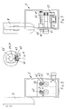
- the improved device comprises a flap cutting assembly, supported on a framework 5 which can be driven transversely of the paperboard material feeding direction.
- the framework 5 is driven by a worm screw 4, in turn driven by a geared motor unit, controlled by a specifically designed electronic apparatus.
- the geared motor unit 11 is supported by said framework 5 for operatively driving, through a toothed pulley 14, a toothed belt 13.
- the belt 13 rotatively drives at least four toothed pulleys 15, 16, 17 and 18 which are rigid with corresponding rotatively driven shafts.
- the two top shafts 60 and 61 as suitably supported, comprise two friction assemblies 51, which are electrically driven, for allowing motion to be transmitted from a primary shaft 60 and 61 to a secondary shaft 60' and 61', at electronically preset time periods.
- the two shafts 60 and 61 can be driven by electronically controlled motors.
- the secondary shafts 60' and 61' support two rotary devices 19 and 20 in turn supporting a plurality of cutting blades or knives 62.
- the cutting blades will respectively cut a paperboard material side flap, thereby forming the box paperboard flap 74, the length of which will be electronically preset, in setting the box dimensions.
- the joining flap 74 cutting blades 62 during the paperboard material cutting operation, turn with two bottom ring elements 21 and 22 made of a hardened steel material.
- the bottom ring elements 21 and 22 adjoin two further ring elements 23 and 24 coated by a rubber material and which, in tun, cooperate with top rubber wheels 23' and 24' supported by spring-urged arms.
- Said ring elements 23 and 24 and wheels 23' and 24' rotate with a peripheral speed equal to that of the splitting and counter-splitting discs of the splitting machine.
- the ring elements 23 and 24 and wheels 23' and 24' will cause the paperboard material to be evenly fed for cutting the joining flaps therefrom.
- the joining flap blades 62 supported by the two top secondary shafts 60' and 61' comprise resilient material spacer elements, allowing the cutting blades 62 to be urged by a constant pressure, thereby providing a perfect cutting of the joining flaps, independently from the paperboard material thickness and type or quality.
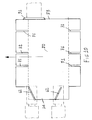
- the auxiliary trimming device for application to the paperboard material splitting machine and to corrugated paperboard material processing machines in general, comprises a supporting framework 6 which can be driven transversely of the paperboad material feeding direction.
- the supporting framework 6, in particular, is preferably driven by a geared motor unit 3, rotatively driving a worm screw 2 engaging with a ring-nut 10 applied to said supporting framework 6.
- a second geared motor unit 34 drives either a toothed pulley 35 or a pinion.
- the pulley 35 drives, through a toothed belt 37, at least four pulleys 40, 41 and 75, which are rigid with four shafts 30, 30', 38 and 39.
- Two of said shafts i.e. a top shaft and a bottom shaft, respectively support a blade 31 and a counter-blade 32 for trimming a side flaps 73 of the paperboard material.
- the rotary shaft 30' supports one or more top cross cutting blades 42 cooperating with a bottom roller, made of a steel material or coated by a polyurethane material 32, thereby transversely pre-cutting the paperboard material portion to be trimmed.
- the subject device further comprises, on the two sides thereof, spring-urged rubber wheels, cooperating with rubber coated ring elements for providing a perfect and even feeding of the paperboard material.
Landscapes
- Life Sciences & Earth Sciences (AREA)
- Forests & Forestry (AREA)
- Engineering & Computer Science (AREA)
- Mechanical Engineering (AREA)
- Making Paper Articles (AREA)
- Auxiliary Devices For And Details Of Packaging Control (AREA)
- Control And Other Processes For Unpacking Of Materials (AREA)
Abstract
Description
Claims (19)
- An improved device, to be applied to paperboard material splitting machines, for forming box joining-flaps, characterized in that said device comprises a supporting framework for supporting a joining flap cutting assembly, said supporting framework being driven transversely of the paperboard material feeding direction, as controlled by a worm screw in turn driven by an electronically controlled geared motor unit.
- An improved device according to Claim 1, characterized in that said joining-flap cutting assembly comprises a supporting framework supporting a geared motor unit which, through a toothed pulley, drives a toothed belt.
- An improved device according to Claim 1, characterized in that said supporting framework is driven by a chain-pinion assembly.
- An improved device according to Claim 2, characterized in that said toothed belt rotatively drives at least four toothed pulleys, which are rigid with corresponding rotary shafts.
- An improved device according to Claim 4, characterized in that said shafts comprise two top shafts supporting two mechanical friction assemblies, or electrically driven assemblies, for allowing motion to be transmitted from a primary shaft to a secondary shaft at mechanically or electronically set time periods.
- An improved device according to Claim 5, characterized in that said secondary shafts support two cutting blade supporting rotary devices.
- An improved device according to Claim 6, characterized in that, as said cutting blade supporting rotary devices are rotatively driven, they respectively cut a front and rear flap of the paperboard material, thereby providing the box paperboard joining flap, the length of said joining flap being electronically preset as the box dimensions are set.
- An improved device according to Claim 7, characterized in that said joining flap cutting blades are rotatively driven, for cutting the paperboard material, in cooperation with two bottom hardened steel ring elements.
- An improved device according to Claim 8, characterized in that said hardened steel bottom ring elements adjoin two further rubber coated ring elements which cooperate with top rubber wheel supported by spring-urged arms.
- An improved device according to Claim 9, characterized in that said rubber coated ring elements and wheels turn with a peripheral speed equal to that of the paperboard splitting and counter-splitting discs of the paperboard splitting machine.
- An improved device according to Claim 10, characterized in that said rubber coated ring elements and wheels cause said paperboard material to be evenly fed as said joining flap is cut therefrom.
- An improved device according to Claim 9, characterized in that said joining flap cutting blades, supported by said two top secondary shafts, comprise resilient material spacer elements applying on the cutting blades an even pressure so as to cut the joining flap independently from the thickness and type of the paperboard material.
- An improved device according to Claim 1, characterized in that said device further comprises an auxiliary trimming assembly, for application to paperboard material splitting or die-cutting machines and to corrugated board processing machines in general, said trimming assembly comprising a supporting framework which can be driven transversely of the paperboard material feeding direction.
- An improved device according to Claim 13, characterized in that said supporting framework is driven by a geared motor assembly rotatively driving a worm screw engaging with a ring-nut applied to said auxiliary supporting framework.
- An improved device according to Claim 1, characterized in that said device comprises a second geared motor unit driving a toothed pulley or a pinion.
- An improved device according to Claim 15, characterized in that said toothed pulley drives, through a toothed belt, a plurality of pulleys rigid with at least four shafts.
- An improved device according to Claim 16, characterized in that two of said four shafts, i.e. a top shaft and a bottom shaft, respectively support a cutting blade and a cutting counter-blade, for trimming a side flap of said paperboard material.
- An improved device according to Claim 17, characterized in that the other two shafts of said four shafts, which are also rotatively driven, respectively support one or more top cross cutting blades.
- An improved device according to Claim 18, characterized in that said one or more top cross cutting blades cooperate with a bottom roller, made of a steel material or of a polyurethane coated material, thereby cross pre-cutting the paperboard material portion to be trimmed.
Applications Claiming Priority (2)
| Application Number | Priority Date | Filing Date | Title |
|---|---|---|---|
| ITMI010716 | 2001-04-03 | ||
| IT2001MI000716A ITMI20010716A1 (en) | 2001-04-03 | 2001-04-03 | PERFECTED DEVICE APPLICABLE TO CUTTING MACHINES ABLE TO FIND THE JOINTING BASE PLATES OF THE BOXES |
Publications (2)
| Publication Number | Publication Date |
|---|---|
| EP1247625A2 true EP1247625A2 (en) | 2002-10-09 |
| EP1247625A3 EP1247625A3 (en) | 2004-10-13 |
Family
ID=11447434
Family Applications (1)
| Application Number | Title | Priority Date | Filing Date |
|---|---|---|---|
| EP20020006890 Withdrawn EP1247625A3 (en) | 2001-04-03 | 2002-03-26 | Device for forming box joining flaps in a box blanks splitting machine |
Country Status (3)
| Country | Link |
|---|---|
| US (1) | US6652434B2 (en) |
| EP (1) | EP1247625A3 (en) |
| IT (1) | ITMI20010716A1 (en) |
Cited By (2)
| Publication number | Priority date | Publication date | Assignee | Title |
|---|---|---|---|---|
| WO2013029768A1 (en) | 2011-08-31 | 2013-03-07 | Bobst Lyon | Device for treating a plate-shaped element, treatment unit, and machine for manufacturing packaging |
| CN103817728A (en) * | 2014-03-19 | 2014-05-28 | 吕孟强 | Transverse cutting machine |
Families Citing this family (3)
| Publication number | Priority date | Publication date | Assignee | Title |
|---|---|---|---|---|
| ITMI20020273A1 (en) * | 2002-02-12 | 2003-08-12 | Engico Srl | DIE CUTTER DEVICE SUITABLE FOR PERFORMING SLITS PERPENDICULAR TO THE DIRECTION FOR ADVANCING CARDBOARD SHEETS USED FOR THE FABBR |
| CN111497325A (en) * | 2019-03-13 | 2020-08-07 | 金洁 | Manufacturing mechanism of packing box |
| IT201900012114A1 (en) * | 2019-07-17 | 2021-01-17 | Emmeci Spa | NOTCHING MACHINE |
Family Cites Families (13)
| Publication number | Priority date | Publication date | Assignee | Title |
|---|---|---|---|---|
| US2807197A (en) * | 1956-12-05 | 1957-09-24 | Kieckhefer Container Company | Apparatus for cutting flattened containers |
| US2982189A (en) * | 1957-09-06 | 1961-05-02 | S & S Corrugated Paper Mach | Power driven adjusting means for slotting, scoring, creasing and slitting machine |
| US3443491A (en) * | 1966-08-29 | 1969-05-13 | Senior Products Ltd | Manufacture of boxes or cartons |
| US3552251A (en) * | 1968-12-03 | 1971-01-05 | Bobst Champlain Inc | Rotary slit cutter |
| US3776072A (en) * | 1971-02-26 | 1973-12-04 | Gerber Garment Technology Inc | Method and apparatus for cutting sheet material |
| US4030662A (en) * | 1975-05-14 | 1977-06-21 | Gess Larry C | Package and method and apparatus for producing same |
| US3985054A (en) * | 1975-06-23 | 1976-10-12 | Fedders Corporation | Cutting mechanism |
| JPS6040238A (en) * | 1983-08-12 | 1985-03-02 | 株式会社磯輪鉄工所 | Method of controlling positioning in corrugated board processing machine |
| US4596541A (en) * | 1983-09-09 | 1986-06-24 | The Ward Machinery Company | Slit-score method and apparatus |
| US5181899A (en) * | 1992-02-14 | 1993-01-26 | Lawrence Paper Company | Adjustable slotter wheel and sheet feeder retrofit apparatus for box blank making machines |
| GB2297682B (en) * | 1995-02-08 | 1997-01-15 | Gerber Garment Technology Inc | Apparatus and method for bite cutting pattern pieces for made to order garments |
| US5546838A (en) * | 1995-04-28 | 1996-08-20 | The Upper Deck Company | Notch timing device and method for card slitting machine |
| US5964686A (en) * | 1997-11-07 | 1999-10-12 | Griffin Automation, Inc. | Method for forming slotted and creased box blanks |
-
2001
- 2001-04-03 IT IT2001MI000716A patent/ITMI20010716A1/en unknown
-
2002
- 2002-03-26 EP EP20020006890 patent/EP1247625A3/en not_active Withdrawn
- 2002-04-01 US US10/113,349 patent/US6652434B2/en not_active Expired - Lifetime
Cited By (3)
| Publication number | Priority date | Publication date | Assignee | Title |
|---|---|---|---|---|
| WO2013029768A1 (en) | 2011-08-31 | 2013-03-07 | Bobst Lyon | Device for treating a plate-shaped element, treatment unit, and machine for manufacturing packaging |
| US11141947B2 (en) | 2011-08-31 | 2021-10-12 | Bobst Lyon | Device for processing a plate element, processing unit and packaging production machine |
| CN103817728A (en) * | 2014-03-19 | 2014-05-28 | 吕孟强 | Transverse cutting machine |
Also Published As
| Publication number | Publication date |
|---|---|
| ITMI20010716A0 (en) | 2001-04-03 |
| US6652434B2 (en) | 2003-11-25 |
| US20020142906A1 (en) | 2002-10-03 |
| EP1247625A3 (en) | 2004-10-13 |
| ITMI20010716A1 (en) | 2002-10-03 |
Similar Documents
| Publication | Publication Date | Title |
|---|---|---|
| EP1480790B1 (en) | Soft goods slitter and feed system for quilting | |
| JP3100240B2 (en) | Disk type rotary cutter | |
| EP2142694B1 (en) | Improved soft goods slitter and feed system for quilting | |
| EP1338389B1 (en) | Die-cutting device for performing slots perpendicular to the feeding direction of box-forming paperboard sheets | |
| US3974727A (en) | Rotary knife, assembly and machine for processing a product | |
| EP1121914A2 (en) | Method and module for making adhesive bandages | |
| US6652434B2 (en) | Device for forming box joining flaps in a box splitting machine | |
| JPH08187693A (en) | A method for cutting a flat printed material along a predetermined cutting line | |
| US7117776B1 (en) | High-speed shear for transverse cutting of a rolled strip | |
| US20020043145A1 (en) | Device for cutting large-format tiles | |
| KR20010070167A (en) | Rotary cutting machine for corrugated cardboard plate | |
| CN2230640Y (en) | Disc cutter | |
| US2948312A (en) | Machine to prepare precisely the edges of sheet material for veneering and the like | |
| EP0955156B1 (en) | Device for slotting and creasing a sheet cardboard material | |
| CN214025908U (en) | A shearing machine with strong versatility | |
| KR200312019Y1 (en) | Apparatus which is cutting bending grooves in cutting blades | |
| KR100504212B1 (en) | An auto-manufacturing apparatus for cutting part a plastics board | |
| KR200199293Y1 (en) | Corrugated cardbord cutting machine | |
| US6715393B2 (en) | Cutting apparatus having adjustable cutter assembly | |
| CZ412197A3 (en) | Tool for automatic cutting-off edges formed during moulding half-finished products of plastic | |
| EP0364300A3 (en) | Rotary die cutter | |
| RU2063155C1 (en) | Shoe part thickness leveling machine | |
| US20050103178A1 (en) | Device for trimming a print product | |
| CN222294102U (en) | Cutting machine for leather product processing | |
| KR20010098979A (en) | Corrugated cardbord cutting machine |
Legal Events
| Date | Code | Title | Description |
|---|---|---|---|
| PUAI | Public reference made under article 153(3) epc to a published international application that has entered the european phase |
Free format text: ORIGINAL CODE: 0009012 |
|
| AK | Designated contracting states |
Kind code of ref document: A2 Designated state(s): AT BE CH CY DE DK ES FI FR GB GR IE IT LI LU MC NL PT SE TR |
|
| AX | Request for extension of the european patent |
Free format text: AL;LT;LV;MK;RO;SI |
|
| RIC1 | Information provided on ipc code assigned before grant |
Ipc: 7B 31B 1/20 B Ipc: 7B 26D 3/14 B Ipc: 7B 26D 3/12 A |
|
| PUAL | Search report despatched |
Free format text: ORIGINAL CODE: 0009013 |
|
| AK | Designated contracting states |
Kind code of ref document: A3 Designated state(s): AT BE CH CY DE DK ES FI FR GB GR IE IT LI LU MC NL PT SE TR |
|
| AX | Request for extension of the european patent |
Extension state: AL LT LV MK RO SI |
|
| 17P | Request for examination filed |
Effective date: 20050321 |
|
| AKX | Designation fees paid |
Designated state(s): AT BE CH CY DE DK ES FI FR GB GR IE IT LI LU MC NL PT SE TR |
|
| STAA | Information on the status of an ep patent application or granted ep patent |
Free format text: STATUS: THE APPLICATION IS DEEMED TO BE WITHDRAWN |
|
| 18D | Application deemed to be withdrawn |
Effective date: 20061130 |