EP1247486A2 - Electronic blood pressure monitor - Google Patents
Electronic blood pressure monitor Download PDFInfo
- Publication number
- EP1247486A2 EP1247486A2 EP02005061A EP02005061A EP1247486A2 EP 1247486 A2 EP1247486 A2 EP 1247486A2 EP 02005061 A EP02005061 A EP 02005061A EP 02005061 A EP02005061 A EP 02005061A EP 1247486 A2 EP1247486 A2 EP 1247486A2
- Authority
- EP
- European Patent Office
- Prior art keywords
- wrist
- pressure
- pulse wave
- pressurizing unit
- blood pressure
- Prior art date
- Legal status (The legal status is an assumption and is not a legal conclusion. Google has not performed a legal analysis and makes no representation as to the accuracy of the status listed.)
- Withdrawn
Links
Images





Classifications
-
- A—HUMAN NECESSITIES
- A61—MEDICAL OR VETERINARY SCIENCE; HYGIENE
- A61B—DIAGNOSIS; SURGERY; IDENTIFICATION
- A61B5/00—Measuring for diagnostic purposes; Identification of persons
- A61B5/68—Arrangements of detecting, measuring or recording means, e.g. sensors, in relation to patient
- A61B5/6801—Arrangements of detecting, measuring or recording means, e.g. sensors, in relation to patient specially adapted to be attached to or worn on the body surface
- A61B5/6802—Sensor mounted on worn items
- A61B5/681—Wristwatch-type devices
-
- A—HUMAN NECESSITIES
- A61—MEDICAL OR VETERINARY SCIENCE; HYGIENE
- A61B—DIAGNOSIS; SURGERY; IDENTIFICATION
- A61B5/00—Measuring for diagnostic purposes; Identification of persons
- A61B5/02—Detecting, measuring or recording for evaluating the cardiovascular system, e.g. pulse, heart rate, blood pressure or blood flow
- A61B5/021—Measuring pressure in heart or blood vessels
- A61B5/022—Measuring pressure in heart or blood vessels by applying pressure to close blood vessels, e.g. against the skin; Ophthalmodynamometers
- A61B5/02233—Occluders specially adapted therefor
Definitions
- the present invention relates to an electronic blood pressure monitor for measuring a blood pressure at a wrist.
- An electronic blood pressure monitor for measuring a blood pressure at a wrist generally has a cuff to be wound around a wrist and a body provided integrally with or separately from the cuff.
- the cuff is provided with a pulse wave sensor for extracting pulse wave data of a region of an organism, and the body is provided with a display unit for displaying a blood pressure value and the like, and an operation unit for instructing start of measurement and the like.
- the radius 31, ulna 32, radial artery 33, and ulnar artery 34 exist in a wrist 30, the radius 31, ulna 32, radial artery 33, and ulnar artery 34 exist.
- the depth at which the radial artery 33 exists from the surface of an organism at the wrist 30 and that of the ulnar artery 34 at the wrist 30 are different from each other .
- the radial artery 33 is positioned closer to the surface of the wrist 30 than the ulnar artery 34.
- the cuff pressure obtained by checking the blood flow in the radial artery 33 and that in the ulnar artery 34 are different from each other.
- the blood flow in the radial artery 33 positioned closer to the surface of the wrist 30 is checked at the cuff pressure lower than that of the ulnar artery 34.
- a conventional wrist blood pressure monitor presses the radial artery 33 and the ulnar artery 34 simultaneously with a cuff wound around the wrist 30 and obtains a pulse wave signal. Consequently, when attention is paid to the radial artery 33, even if the cuff pressure achieves the cuff pressure obtained at which the blood flow in the radial artery 33 is completely checked (i.e., the highest blood pressure), there is a case that the blood flow in the ulnar artery 34 is not checked yet. In order to completely check the blood flow in the ulnar artery 34 as well, the cuff pressure has to be further increased.
- the cuff of the conventional wrist blood pressure monitor is a pressurizing unit having the same air line across the whole unit, the pressure of a pressing face attached to the wrist 30 on the radius side and that on the ulna side are the same.
- the pressure to the radial artery 33 and that to the ulnar artery 34 are different from each other. Consequently, pulse wave data obtained by the pulse wave sensor is combination of pulse wave data from the radial artery 33 and pulse wave data from the ulnar artery 34. More specifically, as shown in Fig.
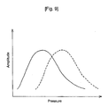
- an envelope of a pulse wave signal obtained by the cuff for the conventional wrist blood pressure monitor often has two peaks (refer to Fig. 9) such that a pulse wave signal from the radial artery 33 appears first and a pulse wave signal from the ulnar artery 34 appears next. Due to this, it has been difficult to determine the blood pressure accurately.
- the present invention has been achieved while paying attention to such a problem and provides an electronic blood pressure monitor with increased measurement accuracy in measurement at the wrist.
- An electronic blood pressure monitor of the present invention includes: a pressurizing unit to be mounted on a wrist of a subject for applying pressure to the wrist; a pressure-increase structure for applying to a portion of the wrist above ulna a pressure higher than a pressure applied to a portion of the wrist above radius, the structure being connected to the pressurizing unit; a pulse wave detecting device for extracting pulse wave data from measured pressure data of the pressurizing unit; a measuring device for measuring blood circulation dynamics using the pulse wave data; and a display unit for displaying a result of measurement of the blood circulation dynamics .
- the ulna portion is pressed by the pressure-increase structure with a pressure higher than a pressure applied to the radial portion.
- the ulnar artery is positioned on the inner side as compared with the radial artery from the surface of an organism, since the ulna portion is pressed with a stronger force, the pressure to the radial artery and that to the ulnar artery can be made substantially the same, and the blood flow in both of the radial and ulnar arteries is checked.
- the time of measuring the blood pressure unlike the conventional technique, only pulse wave data from the radial artery can be extracted, so that the blood pressure can be accurately measured.
- a pressure-increase structure for applying a pressure higher than the above-described pressure to the ulna portion may be also provided.
- the pressure-increase structure in the electronic blood pressure monitor has an extrusion provided on the pressurizing unit so that the extrusion is placed over ulna when the pressurizing unit is mounted on the wrist.
- the extrusion has a width narrower than a width of the pressurizing unit.
- the extrusion may be made of a non-compressible material or may be an air bag connected to an air line different from an air line connected to the pressurizing unit. When sandwiched between the pressurizing unit and the wrist, the non-compressible material is not so compressed as air but has moderate hardness to sufficiently closes the ulnar artery existing in the wrist.
- Substances corresponding to the material are gel, a polymer of high molecule compound, rubber, solution, liquid closed in a bag, sponge and the like.
- An electronic blood pressure monitor of another embodiment of the invention includes: a pressurizing unit to be mounted on a wrist of a subject for applying pressure to the wrist; a vibration absorption structure provided on or in the pressurizing unit for absorbing wave pulse vibration at a portion of the wrist above ulna; a pulse wave detecting device for extracting pulse wave data from measured pressure data of the pressurizing unit; a measuring device for measuring blood circulation dynamics using the pulse wave data; and a display unit for displaying a result of measurement of the blood circulation dynamics.
- pulse wave vibration from the ulnar artery is absorbed by the vibration absorption structure. More specifically, even in a state where although the blood flow in the radial artery is checked, the blood flow in the ulnar artery is not completely checked, the pulse wave vibration from the ulnar artery is absorbed by the vibration absorption structure. As a result, only the pulse wave data of the radial artery can be extracted and, similarly, the blood pressure can be measured accurately.
- the vibration absorption structure in the electronic blood pressure monitor has, for example, a vibration absorption material provided on or in the pressuring unit so that the absorption structure is placed over ulna when the pressuring unit is mounted on the wrist.
- a vibration absorption material is a shock absorbing gel
- the shock absorbing gel is made of, for example, a polymer of high molecule compound.
- blood circulation dynamics measured by the measuring device denotes pressure (the highest blood pressure and the lowest blood pressure) or a blood vessel state.
- Fig. 1 is a perspective view of an electronic blood pressure monitor according to an embodiment of the present invention.
- the electronic blood pressure monitor measures a blood pressure at the wrist, and includes a pressurizing unit (cuff) 1 mounted on the wrist, and a body 2 integrally or detachably provided for the cuff 1.
- the cuff 1 has an air bag inflated/deflated by charging/discharging air, a curler for holding the shape, and a pulse wave sensor for extracting pulse wave data at the wrist.
- the body 2 has a display unit 3 for displaying a blood pressure value, abnormal measurement, and the like, and an operation unit 4 for instructing start of measurement and the like.
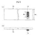
- Figs. 2A and 2B are a partially omitted plan view and a partially omitted side view, respectively, of an example of the shape of the cuff 1 in the electronic blood pressure monitor.
- This cuff 1A has a pressure-increase structure for making the pressure applied to the ulna side of the wrist higher than that applied to the radius side.
- an extrusion 10 having a width narrower than the width of the pressurizing unit is provided on the side corresponding to the ulnar portion.
- the extrusion 10 is positioned near to one end of the cuff 1A, projected from the surf ace of the cuff 1A, and positioned so as to face the ulnar portion when the cuff 1A is mounted on the wrist.
- a width W2 of the extrusion 10 is set to about the half of a width W1 of the cuff 1A.
- the width W2 of the extrusion 10 is 30 to 40 mm
- a length D1 of the extrusion 10 is 10 to 20 mm.
- the extrusion may be a non-compressible material or an air bag connected to an air line different from an air line connected to the pressurizing unit. When sandwiched between the pressurizing unit and the wrist, the non-compressible material is not so compressed as air but has moderate hardness to sufficiently closes the ulnar artery existing in the wrist.
- Substances corresponding to the material are gel, polymer of high molecule compound, rubber, solution, liquid closed in a bag, sponge and the like.
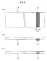
- Figs. 3A and 3B are a partially omitted plan view and a partially omitted side view, respectively, showing another example of the form of the cuff 1 in the electronic blood pressure monitor.
- This cuff 1B has a vibration absorption structure for absorbing pulse wave vibration on the ulna side of the wrist.
- the vibration absorption structure is achieved by providing a vibration absorption material 11 on the side facing the ulna side.
- the vibration absorption material 11 is a shock absorbing gelmadeof, for example, a polymer of high molecule compound.
- the vibration absorbing material 11 is provided over the full width in a position near to one end of the cuff 1B and is slightly projected from the surface of the cuff 1B.
- the length D2 of the vibration absorption material 11 is the same as the length D1 of the extrusion 10, which is 10 to 20 mm.
- the vibration absorption material 11 does not have to be protruded from the surface of the cuff 1B and, as shown in Fig. 3C, the surface of the vibration absorption material 11 and that of the cuff 1B may be approximately flush with each other.
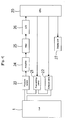
- Fig. 4 is a block diagram showing the general configuration of the electronic blood pressure monitor according to the embodiment.
- the electronic blood pressure monitor has a cuff 1 (the cuff 1A or 1B) mounted on the wrist to press the wrist, a pressurizing pump 21 for increasing the pressure in the cuff 1, an exhaust valve (pressure control unit) 22 for decreasing the pressure in the cuff 1, a pressure sensor (pressure detecting unit) 23 for detecting the pressure in the cuff 1, an amplifier 24 for amplifying an output from the pressure sensor 23, a filter 25 for extracting only a pulse wave component included in a cuff pressure signal as the output of the amplifier 24, an A/D converter 26 for converting analog signals from the amplifier 24 and filter 25 into digital signals and inputting the digital signals to a CPU 20, a display unit 27 for displaying a calculated blood pressure value and the like, and the CPU 20 for controlling the pressurizing pump 21, exhaust valve 22, display unit 27 and the like.
- the CPU 20 has a measuring function of measuring blood circulation dynamics (blood pressure and blood vessel state) on the basis of pulse wave data detected by the pressure sensor 23. That is, the CPU 20 applies a predetermined algorithm to the cuff pressure signal captured and determines the highest and lowest blood pressures.
- the configuration described above is similar to that of the conventional blood pressure monitor.
- the electronic blood pressure monitor according to the embodiment has a feature that the cuff 1 is the cuff 1A or 1B of the above structure.
- Figs. 5 and 6 show states where the cuffs 1A and 1B are mounted on the wrist.
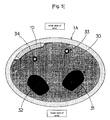
- Fig. 5 is a schematic sectional view showing a state where the cuff 1A is mounted on the wrist 30.
- the extrusion 10 faces the ulnar portion of the wrist 30 and the ulnar portion is pressed by the moderately hard extrusion 10.
- the ulnar portion is pressed harder by the extrusion 10. Consequently, even when the ulnar artery 34 is positioned on the inner side as compared with the radial artery 33 from the surface of an organism, the radial artery 33 and ulnar artery 34 are pressed with approximately same pressure, and the blood flow in both of the arteries is checked.
- the time of measuring the blood pressure only a signal from the radial artery 33 can be selectively extracted, and a signal from the ulnar artery 34 is not mixed, so that accurate blood pressure measurement can be achieved.
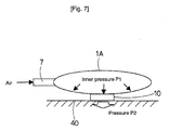
- the width W2 of the extrusion 10 is narrower than the width W1 of the cuff 1A (refer to Fig. 2A), a pressure P2 higher than an internal pressure P1 of the cuff 1A (equal to the pressure on the radius portion) is applied to the ulnar side.
- the principle is as follows.
- the width W2 of the extrusion 10 By setting the width W2 of the extrusion 10 to a fraction (for example, 1/2) of the width W1 of the cuff 1A by using the principle, the pressure of W1/W2 is applied to the ulnar portion. Therefore, by setting the widths W1 and W2 so that the ulnar artery 34 is closed at a usual lowest blood pressure (for example, 50 mmHg) or less, the ulnar artery 34 is closed at a lower cuff pressure as compared with the radial artery 33. As a result, at the time of measuring the blood pressure, only the signal from the radial artery 33 can be selectively extracted, and higher-precision blood pressure measurement can be therefore performed.
- a usual lowest blood pressure for example, 50 mmHg
- the pulse wave signal obtained by using the cuff 1A or 1B is only a pulse wave signal from the radial artery unlike the conventional case (Fig. 11) having two peaks in which the pulse wave signal from the ulnar artery is mixed.
- the pulse wave signal (broken line) from the ulnar artery appears subsequent to the pulse wave signal (solid line) from the radial artery at the time of measuring the blood pressure.
- the pulse wave signal from the ulnar artery does not appear.
- the electronic blood pressure monitor according to the present invention including either the pressurizing unit having the pressure-increase structure or the vibration absorption structure can extract only the pulse wave data from the radial artery at the time of measuring the blood pressure, so that the blood pressure can be accurately measured.
Landscapes
- Health & Medical Sciences (AREA)
- Life Sciences & Earth Sciences (AREA)
- Surgery (AREA)
- Pathology (AREA)
- Cardiology (AREA)
- Veterinary Medicine (AREA)
- Physics & Mathematics (AREA)
- Vascular Medicine (AREA)
- Biophysics (AREA)
- General Health & Medical Sciences (AREA)
- Engineering & Computer Science (AREA)
- Biomedical Technology (AREA)
- Heart & Thoracic Surgery (AREA)
- Medical Informatics (AREA)
- Molecular Biology (AREA)
- Public Health (AREA)
- Animal Behavior & Ethology (AREA)
- Ophthalmology & Optometry (AREA)
- Dentistry (AREA)
- Physiology (AREA)
- Measuring Pulse, Heart Rate, Blood Pressure Or Blood Flow (AREA)
Abstract
Description
Claims (9)
- An electronic blood pressure monitor comprising:a pressurizing unit to be mounted on a wrist of a subject for applying pressure to the wrist;a pressure-increase structure for applying to a portion of the wrist above ulna a pressure higher than a pressure applied to a portion of the wrist above radius, the structure being connected to the pressurizing unit;a pulse wave detecting device for extracting pulse wave data from measured pressure data of the pressurizing unit;a measuring device for measuring blood circulation dynamics using the pulse wave data ; anda display unit for displaying a result of measurement of the blood circulation dynamics.
- The electronic blood pressure monitor of claim 1, wherein the pressure-increase structure comprises an extrusion provided on the pressurizing unit so that the extrusion is placed over ulna when the pressurizing unit is mounted on the wrist, the extrusion having a width narrower than a width of the pressurizing unit.
- The electronic blood pressure monitor of claim 2, wherein the extrusion is made of a non-compressible material.
- The electronic blood pressure monitor of claim 2, wherein the extrusion comprises an air bag connected to an air line different from an air line connected to the pressurizing unit.
- An electronic blood pressure monitor comprising:a pressurizing unit to be mounted on a wrist of a subject for applying pressure to the wrist;a vibration absorption structure provided on or in the pressurizing unit for absorbing wave pulse vibration at a portion of the wrist above ulna;a pulse wave detecting device for extracting pulse wave data from measured pressure data of the pressurizing unit;a measuring device for measuring blood circulation dynamics using the pulse wave data; anda display unit for displaying a result of measurement of the blood circulation dynamics.
- The electronic blood pressure monitor of claim 5, wherein the absorption structure comprises a vibration absorption material provided on or in the pressurizing unit so that the absorption structure is placed over ulna when the pressurizing unit is mounted on the wrist.
- The electronic blood pressure monitor of claim 6, wherein the vibration absorbing material comprises a shock absorbing gel.
- The electronic blood pressure monitor of claim 7, wherein the sock absorbing gel is made of a polymer of high molecule compound.
- An electronic blood pressure monitor comprising:a pressurizing unit to be mounted on a wrist of a subject for applying pressure to the wrist;a pulse wave detecting device for extracting pulse wave data from measured pressure data of the pressurizing unit;a device for preventing a pulse wave generated by ulnaris from being detected by the pulse wave detecting device;a measuring device for measuring blood circulation dynamics using the pulse wave data; anda display unit for displaying a result of measurement of the blood circulation dynamics.
Applications Claiming Priority (2)
| Application Number | Priority Date | Filing Date | Title |
|---|---|---|---|
| JP2001098025A JP2002291708A (en) | 2001-03-30 | 2001-03-30 | Electronic sphygmomanometer |
| JP2001098025 | 2001-03-30 |
Publications (2)
| Publication Number | Publication Date |
|---|---|
| EP1247486A2 true EP1247486A2 (en) | 2002-10-09 |
| EP1247486A3 EP1247486A3 (en) | 2002-11-27 |
Family
ID=18951724
Family Applications (1)
| Application Number | Title | Priority Date | Filing Date |
|---|---|---|---|
| EP02005061A Withdrawn EP1247486A3 (en) | 2001-03-30 | 2002-03-06 | Electronic blood pressure monitor |
Country Status (4)
| Country | Link |
|---|---|
| US (1) | US20020147404A1 (en) |
| EP (1) | EP1247486A3 (en) |
| JP (1) | JP2002291708A (en) |
| CN (1) | CN1378815A (en) |
Cited By (1)
| Publication number | Priority date | Publication date | Assignee | Title |
|---|---|---|---|---|
| EP3539467A4 (en) * | 2016-11-23 | 2020-04-15 | Charmcare Co., Ltd. | Wrist blood pressure monitor |
Families Citing this family (29)
| Publication number | Priority date | Publication date | Assignee | Title |
|---|---|---|---|---|
| US7341561B2 (en) * | 2003-05-30 | 2008-03-11 | Casio Computer Co., Ltd. | Wrist-worn high-accuracy pulsation measuring apparatus |
| USD532519S1 (en) * | 2004-11-22 | 2006-11-21 | Aujla Baldev K | Disposable cover for a blood pressure cuff |
| USD526414S1 (en) | 2004-11-22 | 2006-08-08 | Medport, Llc | Blood pressure monitor |
| US20060111637A1 (en) * | 2004-11-23 | 2006-05-25 | Jacober Jeffrey M | Wrist-mount blood pressure monitor with auditory feature |
| KR101068116B1 (en) * | 2008-05-23 | 2011-09-27 | (주)한별메디텍 | Radial pulse wave sensing device and method for measuring non-invasive continuous blood pressure and arterial elasticity |
| US8123694B2 (en) * | 2008-07-18 | 2012-02-28 | Welch Allyn, Inc. | Electro pneumatic interface for blood pressure system |
| US9801780B2 (en) * | 2009-06-23 | 2017-10-31 | Lifecuff Technologies Inc. | Methods and devices for remote ischemic conditioning via partial limb occlusion |
| WO2011005538A2 (en) * | 2009-06-23 | 2011-01-13 | Boris Leschinsky | Methods and devices for remote ischemic preconditioning and near-continuous blood pressure monitoring |
| JP2012139286A (en) * | 2010-12-28 | 2012-07-26 | Omron Healthcare Co Ltd | Blood pressure measuring apparatus |
| US9724584B1 (en) | 2012-11-15 | 2017-08-08 | Airborne Athletics, Inc. | Sports training machine |
| US9668744B2 (en) | 2015-08-05 | 2017-06-06 | Vasoinnovations, Inc. | Apparatus and method to stop bleeding |
| US11564697B2 (en) | 2013-07-12 | 2023-01-31 | Vasoinnovations Inc. | Apparatus and method to stop bleeding |
| US10213214B2 (en) | 2013-07-12 | 2019-02-26 | Vasoinnovations, Inc. | Method to stop bleeding, with short hemostasis duration using a low dose of anticoagulant |
| US10342551B2 (en) | 2013-07-12 | 2019-07-09 | Vasoinnovations Inc. | Method to stop bleeding, with short hemostasis duration using a low dose of anticoagulant |
| US10888334B2 (en) | 2013-07-12 | 2021-01-12 | Vasoinnovations Inc. | Apparatus and method to stop bleeding |
| US9332994B2 (en) * | 2013-07-12 | 2016-05-10 | Vasoinnovations, Inc. | Apparatus and method to stop bleeding |
| US9308000B2 (en) | 2013-07-12 | 2016-04-12 | Vasoinnovations, Inc. | Method of transradial catheterization, device for ulnar artery compression, and method of use |
| US9949738B2 (en) | 2013-07-12 | 2018-04-24 | Vasoinnovations, Inc. | Method to stop bleeding, with short hemostasis duration using a low dose of anticoagulant |
| WO2017023499A1 (en) * | 2015-08-05 | 2017-02-09 | Vasoinnovations, Inc. | Apparatus and method to stop bleeding |
| CN108024818B (en) | 2015-09-03 | 2021-07-16 | 泰尔茂株式会社 | hemostatic device |
| US11577139B1 (en) | 2016-09-30 | 2023-02-14 | Airborne Athletics, Inc. | Basketball training system |
| US10596436B1 (en) | 2016-11-08 | 2020-03-24 | Airborne Athletics, Inc. | Basketball training system |
| CN107440702A (en) * | 2017-08-21 | 2017-12-08 | 四川康码科技有限公司 | Wearable remote information sends instrument for measuring blood pressure |
| USD972675S1 (en) | 2019-09-06 | 2022-12-13 | Airborne Athletics, Inc. | Basketball passing machine |
| US11135500B1 (en) | 2019-09-11 | 2021-10-05 | Airborne Athletics, Inc. | Device for automatic sensing of made and missed sporting attempts |
| KR102555603B1 (en) * | 2021-04-14 | 2023-07-18 | 계명대학교 산학협력단 | ring-type smart stethoscope and manufacturing method for manufacturing it |
| US12508485B1 (en) | 2021-10-20 | 2025-12-30 | Airborne Athletics, Inc. | Basketball training system |
| JP7757755B2 (en) * | 2021-12-09 | 2025-10-22 | オムロンヘルスケア株式会社 | blood pressure measuring device |
| US12194357B1 (en) | 2022-01-24 | 2025-01-14 | Airborne Athletics, Inc. | Basketball training system with computer vision functionality |
Family Cites Families (4)
| Publication number | Priority date | Publication date | Assignee | Title |
|---|---|---|---|---|
| JP2566280B2 (en) * | 1988-04-15 | 1996-12-25 | 松下電工株式会社 | Wrist blood pressure measurement device |
| FI932881A7 (en) * | 1993-06-22 | 1994-12-23 | Increa Oy | Device for recording parameters related to the circulatory system |
| US5832924A (en) * | 1995-02-16 | 1998-11-10 | Medwave, Inc. | Method of positioning a sensor for determining blood pressure of an artery |
| JP3591302B2 (en) * | 1998-05-08 | 2004-11-17 | オムロンヘルスケア株式会社 | Wrist sphygmomanometer cuff |
-
2001
- 2001-03-30 JP JP2001098025A patent/JP2002291708A/en active Pending
-
2002
- 2002-03-06 EP EP02005061A patent/EP1247486A3/en not_active Withdrawn
- 2002-03-22 US US10/103,130 patent/US20020147404A1/en not_active Abandoned
- 2002-03-28 CN CN02108313.4A patent/CN1378815A/en active Pending
Cited By (1)
| Publication number | Priority date | Publication date | Assignee | Title |
|---|---|---|---|---|
| EP3539467A4 (en) * | 2016-11-23 | 2020-04-15 | Charmcare Co., Ltd. | Wrist blood pressure monitor |
Also Published As
| Publication number | Publication date |
|---|---|
| CN1378815A (en) | 2002-11-13 |
| EP1247486A3 (en) | 2002-11-27 |
| US20020147404A1 (en) | 2002-10-10 |
| JP2002291708A (en) | 2002-10-08 |
Similar Documents
| Publication | Publication Date | Title |
|---|---|---|
| US20020147404A1 (en) | Electronic blood pressure monitor | |
| US8579826B2 (en) | Arteriosclerosis degree judgment device capable of judging arteriosclerosis degree precisely | |
| US7083573B2 (en) | Cuff of wrist-mount blood pressure monitor | |
| US6869403B2 (en) | Blood-pressure determining apparatus | |
| US6315734B1 (en) | Pulse-wave propagation information obtaining apparatus | |
| WO2002005726A3 (en) | Non-invasive measurement of suprasystolic signals | |
| WO1998004182A3 (en) | Diagnosing medical conditions by monitoring arterial tone | |
| US6802814B2 (en) | Pressure-pulse-wave detecting apparatus | |
| JP3604808B2 (en) | Body fluid analyzer | |
| JPH05269089A (en) | Sphygmomanometer and its cuff | |
| JPH04256727A (en) | Blood pressure detector | |
| US7182732B2 (en) | Blood pressure meter cuff | |
| JPH1024028A (en) | Body fluid analyzer | |
| JP4795777B2 (en) | Blood pressure measurement cuff, blood pressure measurement device, and blood pressure measurement method | |
| US20040171941A1 (en) | Blood flow amount estimating apparatus | |
| CN102724912B (en) | Blood pressure information measurement device and method for controlling the same | |
| JPH04102438A (en) | Pulse wave detector | |
| US20040199080A1 (en) | Pulse wave measuring apparatus of high measurement accuracy | |
| US20090275845A1 (en) | Method and device for the non-invasive detection of blood flow and associated parameters in particular arterial waveform and blood pressure | |
| JP2012152372A (en) | Blood pressure measurement device and blood pressure measurement method | |
| JP5187783B2 (en) | Automatic blood pressure monitor | |
| JPH0810301Y2 (en) | Pulse wave detector | |
| JPH105198A (en) | Body fluid analyzer | |
| JPH06311972A (en) | Photoelectric blood pressure measurement device | |
| JP2002191567A (en) | Blood pressure cuff |
Legal Events
| Date | Code | Title | Description |
|---|---|---|---|
| PUAI | Public reference made under article 153(3) epc to a published international application that has entered the european phase |
Free format text: ORIGINAL CODE: 0009012 |
|
| AK | Designated contracting states |
Kind code of ref document: A2 Designated state(s): AT BE CH CY DE DK ES FI FR GB GR IE IT LI LU MC NL PT SE TR |
|
| AX | Request for extension of the european patent |
Free format text: AL;LT;LV;MK;RO;SI |
|
| PUAL | Search report despatched |
Free format text: ORIGINAL CODE: 0009013 |
|
| AK | Designated contracting states |
Kind code of ref document: A3 Designated state(s): AT BE CH CY DE DK ES FI FR GB GR IE IT LI LU MC NL PT SE TR |
|
| AX | Request for extension of the european patent |
Free format text: AL;LT;LV;MK;RO;SI |
|
| AKX | Designation fees paid | ||
| REG | Reference to a national code |
Ref country code: DE Ref legal event code: 8566 |
|
| STAA | Information on the status of an ep patent application or granted ep patent |
Free format text: STATUS: THE APPLICATION IS DEEMED TO BE WITHDRAWN |
|
| 18D | Application deemed to be withdrawn |
Effective date: 20030528 |