EP1246346A2 - AC generator having air port in slip ring cover - Google Patents
AC generator having air port in slip ring cover Download PDFInfo
- Publication number
- EP1246346A2 EP1246346A2 EP02005532A EP02005532A EP1246346A2 EP 1246346 A2 EP1246346 A2 EP 1246346A2 EP 02005532 A EP02005532 A EP 02005532A EP 02005532 A EP02005532 A EP 02005532A EP 1246346 A2 EP1246346 A2 EP 1246346A2
- Authority
- EP
- European Patent Office
- Prior art keywords
- slip ring
- generator
- wall portion
- ring cover
- brush holder
- Prior art date
- Legal status (The legal status is an assumption and is not a legal conclusion. Google has not performed a legal analysis and makes no representation as to the accuracy of the status listed.)
- Granted
Links
Images



Classifications
-
- H—ELECTRICITY
- H02—GENERATION; CONVERSION OR DISTRIBUTION OF ELECTRIC POWER
- H02K—DYNAMO-ELECTRIC MACHINES
- H02K5/00—Casings; Enclosures; Supports
- H02K5/04—Casings or enclosures characterised by the shape, form or construction thereof
- H02K5/14—Means for supporting or protecting brushes or brush holders
-
- H—ELECTRICITY
- H02—GENERATION; CONVERSION OR DISTRIBUTION OF ELECTRIC POWER
- H02K—DYNAMO-ELECTRIC MACHINES
- H02K5/00—Casings; Enclosures; Supports
- H02K5/04—Casings or enclosures characterised by the shape, form or construction thereof
- H02K5/14—Means for supporting or protecting brushes or brush holders
- H02K5/141—Means for supporting or protecting brushes or brush holders for cooperation with slip-rings
-
- H—ELECTRICITY
- H02—GENERATION; CONVERSION OR DISTRIBUTION OF ELECTRIC POWER
- H02K—DYNAMO-ELECTRIC MACHINES
- H02K11/00—Structural association of dynamo-electric machines with electric components or with devices for shielding, monitoring or protection
- H02K11/04—Structural association of dynamo-electric machines with electric components or with devices for shielding, monitoring or protection for rectification
- H02K11/049—Rectifiers associated with stationary parts, e.g. stator cores
- H02K11/05—Rectifiers associated with casings, enclosures or brackets
Definitions
- the present invention relates to an AC generator for a vehicle mounted on a passenger car, a truck and the like.
- cooling air is introduced into the sliding contact portion between slip rings and brushes to prevent foreign matters such as water, oil and the like from entering that portion.
- a sealing rubber which has an air passage communicating with the sliding contact portion between the slip ring and the brush.
- the sealing rubber is pressed onto and made to abut against the edge portion of the slip ring cover in an elastically deformed state by a rear cover, thereby securing hermetic sealing around the slip ring.
- the sealing rubber can not uniformly be pressed onto the edge portion of the slip ring cover, so that it is difficult to secure stable hermetic sealing. Further, since the sealing rubber is elastically deformed, an air passage area formed by the sealing rubber is reduced to cause a shortage of cooling air passing through the sliding contact portion between the slip ring and the brush.
- a depression is formed on a brush holder and in which a partitioning portion formed on a slip ring cover is inserted into the depression to form a bent air passage communicating with the sliding contact portion of a slip ring. Since it has a labyrinth structure at the end portion in the axial direction, its size in the axial direction needs to be increased so as to secure a desired amount of suction air, which is contrary to a recent request for a reduction in size.
- an AC generator for a vehicle has a rotor and a brush unit.
- the rotor has a rotary shaft, a field winding, and a slip ring provided on one end of the rotary shaft and electrically connected to the field winding.
- the brush unit has a brush held in sliding contact with the slip ring, a spring for pressing the brush, a brush holder having a portion for receiving the brush, and a slip ring cover for covering the outer periphery of the slip ring.
- An air suction/discharge port is formed in a peripheral direction of the slip ring cover.
- an alternating current (AC) generator 1 is constructed with a stator 2, a rotor 3, frames 4, a brush unit 5, a rectifier 6, a rear cover 7 and the like.
- the stator 2 is provided with a stator core 22, a three-phase stator winding 23, and an insulator 24 for electrically insulating the stator core 22 from the stator winding 23.
- the rotor 3 is provided with a field winding 31 and pole cores 32.
- the field winding is formed by winding an insulated copper wire cylindrically and coaxially and is sandwiched from both sides by the pole cores 32.
- Each pole core 32 has six claws with a rotary shaft 33 inserted into the radial center thereof.
- a cooling fan 35 for discharging cooling air sucked from the front side in the axial direction and in the radial direction is mounted by welding on the axial end surface of the pole core 32 on the front side.
- a cooling fan 36 for discharging cooling air sucked from the rear side in the radial direction is mounted by welding on the axial end surface of the pole core 32 on the rear side.
- two slip rings 37 and 38 are formed in the vicinity of the axial end portion on the rear side of the rotary shaft 33. The slip rings 37 and 38 are electrically connected to both ends of the field winding 31 so that electricity is supplied to the field winding 31 from the brush unit 5.
- the frames 4 receive the stator 2 and the rotor 3.
- the rotor 3 is rotatably supported about the rotary shaft 33.
- the stator 2 is arranged and fixed on the outer peripheral side of the pole core 32 of the rotor 3 with a predetermined gap therebetween.
- the frame 4 has cooling air discharging windows 41 at the portion opposite the stator winding 23 projected from the end surface in the axial direction of the stator core 22 and cooling air sucking windows 42 at the end surface in the axial direction.
- the brush unit 5 is provided to pass an exciting current through the field winding 31 of the rotor 3 from a rectifier 6 and has brushes 51 and 52 pressed on the slip rings 37 and 38 formed on the rotary shaft 33 of the rotor 3.
- the rectifier 6 rectifies a three-phase AC voltage, which is generated as the output voltage of three-phase stator winding 23, to produce a direct current output power.
- the rear cover 7 covers and protects the brush unit 5, the rectifier 6, an IC regulator 9 and the like which are mounted on the outside of the rear side frame 4.
- This rear cover 7 is fastened to a bolt 43 extending from the rear side frame 4 with a metal nut 71 in the state where the rectifier 6 is sandwiched between the rear side frame 4 and the rear cover 7.
- the rotor 3 rotates in a predetermined direction.
- an exciting current is supplied in this state to the field winding 31 of the rotor 3 from the outside, the respective claws of the pole cores 32 are excited to generate a three-phase AC voltage in the stator winding 23 to output a direct current from an output terminal provided on the rectifier 6.
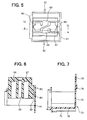
- the brush unit 5 comprises, as shown in Fig. 2 through Fig. 7, a brush holder 60 which is made of resin and in which connection terminals 61 and 62 are buried, a pig tail 63 for electrically connecting the pair of brushes 51 and 52 to the connection terminals 61 and 62, a slip ring cover 70 made of resin, and the springs 64 and 65.
- the brush holder 60 is generally shaped in a box and has openings of brush receiving portions 66, 67, pig tail receiving portions 68, 69 and a radial groove, into which the extending portion 73 of a cover portion 72 of the slip ring cover 70, in the side opposed to the slip rings 37 and 38. Further, on the brush holder 60 is formed a cover portion 81 for closing the end portion in the axial direction at the rear end (side end portion opposite to the pulley) of the rotary shaft 33.
- the pig tail 63 is connected and fixed to the brushes 51 and 52 by caulking copper power and is soldered to the connection terminals 61 and 62 buried in the brush holder 60 at the end portion in the radial direction, thereby being electrically connected to the other parts (the rectifier 6 and the IC regulator 9) connected to the connection terminals 61 and 62.
- the brushes 51 and 52 are pressed onto the slip rings 37 and 38 by the springs 64 and 65 arranged at the back end thereof (on the side opposite to the slip ring).
- the brush holder 60 and the slip ring cover 70 are combined with each other by fitting a projecting portion 74 formed on the cover portion 72 at the axial end of the slip ring cover 70 into an opening 82 formed in the cover portion 81 closing the axial end of the brush holder 60.
- These projecting portion 74 and the opening 82 form a fitting portion and the use of such a fitting portion makes it easy to fixedly assemble the brush holder 60 into the slip ring cover 70, which can improve workability in assembling and tightness.
- the slip ring cover 70 comprises the first wall portion 75, the second wall portion 76 which are nearly shaped like an arc and a side wall portion 77 in addition to the cover portion 72.
- the cover portion 72 is formed so as to close the axial end portion at the rear end of the rotary shaft 33.
- the second wall portion 76 is arranged inside the first wall portion 75 and overlaps the first wall portion 75 in the peripheral direction. Thus, it has air suction/discharge ports 79 in the peripheral direction. That is, the suction/discharge ports 79 each are formed at a portion of the second wall portion 76 and the first wall portion 75 is formed so as to cover the suction/discharge ports 79 to thereby prevent foreign matters from entering the suction/discharge ports 79. Further, a part of the cover portion 81 of the brush holder 60 extends to the first wall portion 75 and closes a gap formed at the axial end side between the second wall portion 76 and the first wall portion 75, thereby preventing the foreign matters from entering the suction/discharge port 79 through the gap.
- the first wall portion 75 has an opening formed in a space communicating with the suction/discharge ports 79 and a projecting portion 78 facing outward in the radial direction is formed along the edge of the opening. The direction of travel of the foreign matters entering the opening along the outer periphery of the first wall portion 75 is changed by the projecting portion 78.
- suction/discharge port 79 is so formed as to face nearly toward the ground in the state where the AC generator 1 is mounted on the vehicle. This can reliably prevent the entry of water drops which become the most significant problem.
- the cover portion 72 of the slip ring cover 70 has an extending portion 73 extending in the radial direction. Then, the extending portion 73 is inserted into the radial groove 80 formed in the brush holder 60 and the cover portion 72 is made to abut against the cover portion 81 to thereby prevent the entry of the foreign matters from the axial end portion. Further, in order to more easily insert the extending portion 73 into the radial groove 80, a tapered surface 83 is formed in the radial groove 80 in the brush holder 60.
- a cylindrical portion formed at the frame side end portion by the brush holder 60 and the slip ring cover 70 is fitted into the center hole, which is formed in the rear side frame 4 to pass the rotary shaft 33, with a small gap. This can secure water tightness at this portion.
- suction/discharge ports 79 are formed in the peripheral direction of the slip ring cover 70 in this manner, when the brush unit 5 is assembled into the AC generator 1, it is possible to prevent the suction/discharge ports 79 from being deformed and thus an air passage area from being reduced, which results in securing a sufficient amount of cooling air. Further, even if the suction/discharge ports 79 each having a sufficient area are formed, they are not increased in size in the axial direction, so that it is possible to reduce the size of the brush unit 5.
- suction/discharge ports 79 are formed without the use of a sealing rubber, it is possible to prevent that an unnecessary gap might be formed between suction/discharge port 79 and the sealing rubber, depending on the state where the brush unit 5 is assembled into the AC generator, and therefore to secure sufficiently hermetic sealing around the slip rings 37 and 38.
- the suction/discharge ports 79 are formed between the first wall portion 75 and the second wall portion 76, the second wall portion 76 can block the foreign matters entering when the cooling air is sucked and therefore can surely prevent the entry of the foreign matters.
- the second wall portion 76 overlaps the first wall portion 75 in the peripheral direction and covers the suction/discharge ports 79, the space communicating with the suction/discharge ports 79 from the outside can be made to have a labyrinth structure and thus can further surely prevent the entry of the foreign matters.
- the first wall portion 75 and the second wall portion 76 may be properly changed in position to thereby properly change the positions of the suction/discharge ports 79.
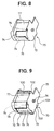
- the slip ring cover 70 may be so modified as shown in Fig. 8. In this modification, the positions of the first wall portion 75 and the second wall portion 76 are changed in the peripheral direction, whereby the position of the suction/discharge ports 79 are changed in the peripheral direction.
- the slip ring cover 70 may be modified as shown in Fig. 9.
- rib-shaped projections 100 and grooves 102 which are both formed on the slip ring cover 70 abutting against the brush holder 60.
- the rib-shaped projections 100 and the grooves 102 both extending in the direction perpendicular to the direction of insertion of the slip ring cover 70 into the brush holder 60.
- the slip ring cover 70 can be assembled into the brush holder 60 in the state where they surely abuts against each other by these projections 100, it is possible to block the foreign matters entering from the gap between the brush holder 60 and the slip ring cover 70 by capillary action.
- the area where the slip ring cover 70 abuts against the brush holder 60 is divided into a plurality of portions by forming the grooves 12, it is possible to block the foreign matters entering from the gap between the brush holder 60 and the slip ring cover 70 by capillary action.
- these rib-shaped projections 100 or the grooves 102 may be formed on all the surfaces of the slip ring cover 70 where the slip ring cover 70 abuts against the brush holder 60. Further, the rib-shaped projections 100 or the grooves 102 may be connected to each other. Still further, only ones of the rib-shaped projections 100 and the grooves 102 may be formed. In particular, even if some of them are formed, the abutting area can be divided into the plurality of portions.
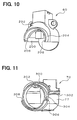
- the brush holder 60 and the slip ring cover 70 may be modified as shown in Fig. 10 and Fig. 11, respectively.
- Fig. 10 shows the shape when viewed in the direction in which the brush holder 60 is assembled into the frame 4
- Fig. 11 shows the shape when viewed in the direction in which the slip ring cover 70 is assembled into the frame.
- These modified brush holder 60 and slip ring cover 70 are assembled as shown in Fig. 12.
- the brush holder 60 shown and the slip ring cover 70 are formed such that a wall portion 200 extending in the axial direction of the brush holder 60 and a wall portion 202 extending in the radial direction covers a part of the slip ring cover 70.
- This construction closes the gap formed between the wall portion 202 and the end portion 300 in the axial direction of the slip ring cover 70 and prevents foreign matters from entering through the gap.
- a rib-shaped projection 302 is formed on the side wall portion 77 of the slip ring cover 77 and the axial end portion 300 (where the slip ring cover 70 is made to abut against the brush holder 60) and is made to abut against the brush holder 60, it is possible to realize a more reliable abutting state.
- a depression 206 is formed on a wall portion 204 extending in the axial direction of the brush holder 60 and a projection 306 is formed on a wall portion 304 of the slip ring cover 70 abutting against the wall portion 204.
- the projection 306 is fitted in the depression 206 to form a fitting portion, the slip ring cover 70 can be easily assembled into and fixed to the brush holder 60. Therefore, this can improve workability in assembling and hermetic sealing.
Landscapes
- Engineering & Computer Science (AREA)
- Power Engineering (AREA)
- Motor Or Generator Current Collectors (AREA)
- Motor Or Generator Frames (AREA)
- Synchronous Machinery (AREA)
- Motor Or Generator Cooling System (AREA)
Abstract
Description
Claims (12)
- An AC generator (1) for a vehicle comprising:wherein a suction/discharge port (79) is formed in a peripheral direction of the slip ring cover.a rotor (3) having a rotary shaft (33), a field winding (31), and a slip ring (37, 38) provided on one end of the rotary shaft and electrically connected to the field winding; anda brush unit (5) having a brush (51, 52) held in sliding contact with the slip ring, a spring (64, 65) for pressing the brush, a brush holder (60) having a portion for receiving the brush, and a slip ring cover (70) for covering the outer periphery of the slip ring,
- The AC generator (1) as in claim 1, wherein the slip ring cover (70) has a first wall portion (75) formed in a shape of an arc in cross section perpendicular to the rotary shaft, and a second wall portion (76) formed inside the first wall portion, and the suction/discharge port (79) is formed between the first wall portion and the second wall portion.
- The AC generator (1) as in claim 2, wherein the first wall portion (75) and the second wall portion (76) overlap in the peripheral direction and covers the suction/discharge port (79).
- The AC generator (1) as in claim 2 or 3, wherein the brush holder (60) partially extends to the first wall portion.
- The AC generator (1) as in any of claims 1 to 4, wherein the suction/discharge port (79) generally faces toward a ground in a state where the AC generator is mounted on a vehicle.
- The AC generator (1) as in any of claims 1 to 5, wherein each of the brush holder (60) and the slip ring cover (70) has a cover portion (72, 81) for closing its end portion at one axial end side of the rotary shaft, and the brush holder (60) is mounted on the slip ring cover (70) in the state where these cover portions are made to abut against each other.
- The AC generator (1) as in claim 6, wherein engaging portions (74, 82) are formed on the cover portions (72, 81) and engaged with each other.
- The AC generator (1) as in any of claims 2 to 4, wherein the first wall portion (75) has an opening made in a space communicating with the suction/discharge port (79), and a projection (100) facing toward outside in the radial direction is formed along the edge of the opening.
- The AC generator (1) as in any of claims 1 to 8, wherein the slip ring cover (70) has a side wall portion (77) formed perpendicularly with respect to the direction of the rotary shaft (33), and at least one of a projection (100) and a groove (102) are formed on the side wall portion to divide area where the slip ring cover (70) abuts against the brush holder (60) into a plurality of portions.
- The AC generator (1) as in any of claims 1 to 9, wherein the brush holder (60) and the slip ring cover (70) have a cylindrical portion formed at a frame side end portion, and the cylindrical portion is fitted with a small gap in a center hole made in a frame (4) to which the brush holder (60) is fixed to pass the rotary shaft (33).
- The AC generator (1) as in any of claims 1 to 10, wherein an extending portion (73) is formed on at least one of end portions of the slip ring cover (70) in an axial direction to extend in a radial direction, and is inserted into a radial groove (80) formed on the brush holder (60).
- The AC generator (1) as in claim 11, wherein the slip ring cover (70) has a rib-shaped projection formed on a surface where the slip ring cover abuts against the brush holder and is made to abut against the brush holder.
Applications Claiming Priority (4)
| Application Number | Priority Date | Filing Date | Title |
|---|---|---|---|
| JP2001096916 | 2001-03-29 | ||
| JP2001096916 | 2001-03-29 | ||
| JP2001383520 | 2001-12-17 | ||
| JP2001383520A JP3855762B2 (en) | 2001-03-29 | 2001-12-17 | AC generator for vehicles |
Publications (3)
| Publication Number | Publication Date |
|---|---|
| EP1246346A2 true EP1246346A2 (en) | 2002-10-02 |
| EP1246346A3 EP1246346A3 (en) | 2003-07-16 |
| EP1246346B1 EP1246346B1 (en) | 2006-05-31 |
Family
ID=26612603
Family Applications (1)
| Application Number | Title | Priority Date | Filing Date |
|---|---|---|---|
| EP02005532A Expired - Lifetime EP1246346B1 (en) | 2001-03-29 | 2002-03-11 | AC generator having air port in slip ring cover |
Country Status (6)
| Country | Link |
|---|---|
| US (1) | US6710499B2 (en) |
| EP (1) | EP1246346B1 (en) |
| JP (1) | JP3855762B2 (en) |
| KR (1) | KR100454691B1 (en) |
| CN (1) | CN1244193C (en) |
| DE (1) | DE60211786T2 (en) |
Cited By (1)
| Publication number | Priority date | Publication date | Assignee | Title |
|---|---|---|---|---|
| FR2905536A1 (en) * | 2006-09-05 | 2008-03-07 | Valeo Equip Electr Moteur | ARRANGEMENT FOR ASSEMBLING AN ADJUSTING CAPSULE AND A PROTECTOR FOR A MANIFOLD OF A ROTATING ELECTRIC MACHINE |
Families Citing this family (18)
| Publication number | Priority date | Publication date | Assignee | Title |
|---|---|---|---|---|
| JP4111172B2 (en) * | 2004-06-16 | 2008-07-02 | 株式会社デンソー | AC generator for vehicles |
| JP4265571B2 (en) * | 2005-06-01 | 2009-05-20 | 株式会社デンソー | Vehicle alternator |
| JP4556808B2 (en) * | 2005-08-23 | 2010-10-06 | 株式会社デンソー | Vehicle alternator |
| JP4566868B2 (en) * | 2005-09-08 | 2010-10-20 | 三菱電機株式会社 | Rotating electric machine for vehicles |
| JP4434154B2 (en) | 2006-02-07 | 2010-03-17 | 株式会社デンソー | Brush generator for AC generator for vehicle |
| JP2007221879A (en) * | 2006-02-15 | 2007-08-30 | Denso Corp | AC generator for vehicles |
| JP4697018B2 (en) * | 2006-04-14 | 2011-06-08 | 株式会社デンソー | AC generator for tandem vehicles |
| JP4687604B2 (en) * | 2006-08-02 | 2011-05-25 | 株式会社デンソー | AC generator for vehicles |
| JP5007537B2 (en) | 2006-08-24 | 2012-08-22 | 株式会社デンソー | AC generator for vehicles |
| US7615908B2 (en) | 2006-09-11 | 2009-11-10 | Denso Corporation | Vehicle alternator with improved operation reliability |
| JP4565345B2 (en) * | 2006-09-11 | 2010-10-20 | 株式会社デンソー | Vehicle alternator |
| DE102008033681B4 (en) | 2007-11-01 | 2022-03-24 | Denso Corporation | Vehicle alternator having a brush assembly covered with an enclosing wall |
| JP4479799B2 (en) * | 2008-01-28 | 2010-06-09 | 株式会社デンソー | Vehicle alternator |
| JP5058298B2 (en) | 2010-05-26 | 2012-10-24 | 三菱電機株式会社 | AC generator for vehicles |
| WO2013021444A1 (en) * | 2011-08-08 | 2013-02-14 | 三菱電機株式会社 | Rotary electric equipment integrated with control device and method for assembly and disassembly thereof |
| JP2016226231A (en) * | 2015-06-03 | 2016-12-28 | 株式会社デンソー | Rotary electric machine |
| JP7027811B2 (en) * | 2017-10-31 | 2022-03-02 | 株式会社デンソー | Brush unit and rotary electric machine |
| DE102020111398A1 (en) | 2020-04-27 | 2021-10-28 | Seg Automotive Germany Gmbh | Brush guide for an electrical machine, slip ring assembly and electrical machine |
Family Cites Families (11)
| Publication number | Priority date | Publication date | Assignee | Title |
|---|---|---|---|---|
| JPS626830Y2 (en) * | 1980-06-10 | 1987-02-17 | ||
| JPS57148554A (en) * | 1981-03-06 | 1982-09-13 | Hitachi Ltd | Cooler for blower driving motor |
| JPS5986851U (en) * | 1982-11-30 | 1984-06-12 | 三菱電機株式会社 | Vehicle alternator |
| JPS602051A (en) | 1983-06-16 | 1985-01-08 | Nippon Denso Co Ltd | Ac generator for vehicle |
| JPS605750A (en) | 1983-06-22 | 1985-01-12 | Hitachi Ltd | Vehicle alternator |
| US4959576A (en) * | 1987-11-25 | 1990-09-25 | Nippondenso Co., Ltd. | Automotive alternator |
| US5047678A (en) * | 1988-08-25 | 1991-09-10 | Mitsubishi Denki K.K. | Generator for vehicle |
| JPH0479224A (en) | 1990-07-20 | 1992-03-12 | Seiko Epson Corp | Cleaning device |
| JP3232706B2 (en) * | 1991-11-06 | 2001-11-26 | 株式会社デンソー | Explosion-proof rotary electric machine |
| JP3911879B2 (en) * | 1998-11-02 | 2007-05-09 | 株式会社デンソー | AC generator for vehicles |
| JP4003334B2 (en) * | 1999-02-04 | 2007-11-07 | 株式会社デンソー | AC generator for vehicles |
-
2001
- 2001-12-17 JP JP2001383520A patent/JP3855762B2/en not_active Expired - Fee Related
-
2002
- 2002-03-01 US US10/085,408 patent/US6710499B2/en not_active Expired - Lifetime
- 2002-03-11 DE DE60211786T patent/DE60211786T2/en not_active Expired - Lifetime
- 2002-03-11 EP EP02005532A patent/EP1246346B1/en not_active Expired - Lifetime
- 2002-03-27 KR KR10-2002-0016739A patent/KR100454691B1/en not_active Expired - Fee Related
- 2002-03-29 CN CNB021049866A patent/CN1244193C/en not_active Expired - Fee Related
Cited By (2)
| Publication number | Priority date | Publication date | Assignee | Title |
|---|---|---|---|---|
| FR2905536A1 (en) * | 2006-09-05 | 2008-03-07 | Valeo Equip Electr Moteur | ARRANGEMENT FOR ASSEMBLING AN ADJUSTING CAPSULE AND A PROTECTOR FOR A MANIFOLD OF A ROTATING ELECTRIC MACHINE |
| WO2008029036A1 (en) * | 2006-09-05 | 2008-03-13 | Valeo Equipements Electriques Moteur | Arrangement for assembling an adjustment cap and a protector for the slip ring assembly of a rotary electrical machine |
Also Published As
| Publication number | Publication date |
|---|---|
| US6710499B2 (en) | 2004-03-23 |
| CN1379532A (en) | 2002-11-13 |
| EP1246346A3 (en) | 2003-07-16 |
| DE60211786D1 (en) | 2006-07-06 |
| JP2002359951A (en) | 2002-12-13 |
| CN1244193C (en) | 2006-03-01 |
| US20020140314A1 (en) | 2002-10-03 |
| EP1246346B1 (en) | 2006-05-31 |
| JP3855762B2 (en) | 2006-12-13 |
| KR100454691B1 (en) | 2004-11-05 |
| KR20020077148A (en) | 2002-10-11 |
| DE60211786T2 (en) | 2006-10-05 |
Similar Documents
| Publication | Publication Date | Title |
|---|---|---|
| EP1246346B1 (en) | AC generator having air port in slip ring cover | |
| KR100225248B1 (en) | Ac generator for a vehicle | |
| US7417353B2 (en) | On-vehicle alternator with brush/slip ring structure | |
| US8193682B2 (en) | Vehicle alternator provided with brushes, brush holder, and slip rings | |
| US20030156954A1 (en) | Compressor unit | |
| US6515398B1 (en) | Alternator having passage for ventilating slip-ring surface | |
| JP2000139058A (en) | AC generator for vehicles | |
| US7057315B2 (en) | Automotive alternator having cooling fan coupled to rotor shaft | |
| US6492752B2 (en) | AC generator for vehicle | |
| US7348700B2 (en) | Automotive alternator having water shield for protecting brushes from water damage | |
| KR20040078158A (en) | Electric Motor | |
| EP1608051B1 (en) | Alternator having a slip-ring cover connected to brush holder | |
| EP1009087A2 (en) | Miniature electric motor | |
| CN107996016B (en) | Vehicle Rotary Electric Machine | |
| KR100440877B1 (en) | Alternator for vehicle | |
| JP4284887B2 (en) | Vehicle alternator | |
| JP2002119009A (en) | Electric rotating machine for vehicles | |
| JP3785964B2 (en) | AC generator for vehicles | |
| JP2002315283A (en) | Electric rotating machine for vehicles | |
| US8089193B2 (en) | Automotive alternator having brush device covered with surrounding wall | |
| KR200168221Y1 (en) | An alternator | |
| KR100406719B1 (en) | Alternator for vehicle | |
| JP2003174754A (en) | Rotating electric machine | |
| JP2001078383A (en) | AC generator for vehicles | |
| JPH11311264A (en) | Exciter for electromagnetic coupling device |
Legal Events
| Date | Code | Title | Description |
|---|---|---|---|
| PUAI | Public reference made under article 153(3) epc to a published international application that has entered the european phase |
Free format text: ORIGINAL CODE: 0009012 |
|
| AK | Designated contracting states |
Kind code of ref document: A2 Designated state(s): AT BE CH CY DE DK ES FI FR GB GR IE IT LI LU MC NL PT SE TR |
|
| AX | Request for extension of the european patent |
Free format text: AL;LT;LV;MK;RO;SI |
|
| PUAL | Search report despatched |
Free format text: ORIGINAL CODE: 0009013 |
|
| AK | Designated contracting states |
Designated state(s): AT BE CH CY DE DK ES FI FR GB GR IE IT LI LU MC NL PT SE TR |
|
| AX | Request for extension of the european patent |
Extension state: AL LT LV MK RO SI |
|
| 17P | Request for examination filed |
Effective date: 20031108 |
|
| AKX | Designation fees paid |
Designated state(s): DE FR GB IT |
|
| 17Q | First examination report despatched |
Effective date: 20050224 |
|
| GRAP | Despatch of communication of intention to grant a patent |
Free format text: ORIGINAL CODE: EPIDOSNIGR1 |
|
| GRAS | Grant fee paid |
Free format text: ORIGINAL CODE: EPIDOSNIGR3 |
|
| GRAA | (expected) grant |
Free format text: ORIGINAL CODE: 0009210 |
|
| AK | Designated contracting states |
Kind code of ref document: B1 Designated state(s): DE FR GB IT |
|
| PG25 | Lapsed in a contracting state [announced via postgrant information from national office to epo] |
Ref country code: IT Free format text: LAPSE BECAUSE OF FAILURE TO SUBMIT A TRANSLATION OF THE DESCRIPTION OR TO PAY THE FEE WITHIN THE PRESCRIBED TIME-LIMIT;WARNING: LAPSES OF ITALIAN PATENTS WITH EFFECTIVE DATE BEFORE 2007 MAY HAVE OCCURRED AT ANY TIME BEFORE 2007. THE CORRECT EFFECTIVE DATE MAY BE DIFFERENT FROM THE ONE RECORDED. Effective date: 20060531 |
|
| REG | Reference to a national code |
Ref country code: GB Ref legal event code: FG4D |
|
| REF | Corresponds to: |
Ref document number: 60211786 Country of ref document: DE Date of ref document: 20060706 Kind code of ref document: P |
|
| ET | Fr: translation filed | ||
| PLBE | No opposition filed within time limit |
Free format text: ORIGINAL CODE: 0009261 |
|
| STAA | Information on the status of an ep patent application or granted ep patent |
Free format text: STATUS: NO OPPOSITION FILED WITHIN TIME LIMIT |
|
| 26N | No opposition filed |
Effective date: 20070301 |
|
| REG | Reference to a national code |
Ref country code: FR Ref legal event code: PLFP Year of fee payment: 15 |
|
| REG | Reference to a national code |
Ref country code: FR Ref legal event code: PLFP Year of fee payment: 16 |
|
| REG | Reference to a national code |
Ref country code: FR Ref legal event code: PLFP Year of fee payment: 17 |
|
| PGFP | Annual fee paid to national office [announced via postgrant information from national office to epo] |
Ref country code: GB Payment date: 20190320 Year of fee payment: 18 Ref country code: IT Payment date: 20190325 Year of fee payment: 18 Ref country code: DE Payment date: 20190321 Year of fee payment: 18 Ref country code: FR Payment date: 20190322 Year of fee payment: 18 |
|
| REG | Reference to a national code |
Ref country code: DE Ref legal event code: R119 Ref document number: 60211786 Country of ref document: DE |
|
| PG25 | Lapsed in a contracting state [announced via postgrant information from national office to epo] |
Ref country code: DE Free format text: LAPSE BECAUSE OF NON-PAYMENT OF DUE FEES Effective date: 20201001 Ref country code: FR Free format text: LAPSE BECAUSE OF NON-PAYMENT OF DUE FEES Effective date: 20200331 |
|
| GBPC | Gb: european patent ceased through non-payment of renewal fee |
Effective date: 20200311 |
|
| PG25 | Lapsed in a contracting state [announced via postgrant information from national office to epo] |
Ref country code: GB Free format text: LAPSE BECAUSE OF NON-PAYMENT OF DUE FEES Effective date: 20200311 |
|
| PG25 | Lapsed in a contracting state [announced via postgrant information from national office to epo] |
Ref country code: IT Free format text: LAPSE BECAUSE OF NON-PAYMENT OF DUE FEES Effective date: 20200311 |