EP1246322A2 - Method and apparatus for minimising gain deviation in optical fibre amplifier - Google Patents
Method and apparatus for minimising gain deviation in optical fibre amplifier Download PDFInfo
- Publication number
- EP1246322A2 EP1246322A2 EP02251194A EP02251194A EP1246322A2 EP 1246322 A2 EP1246322 A2 EP 1246322A2 EP 02251194 A EP02251194 A EP 02251194A EP 02251194 A EP02251194 A EP 02251194A EP 1246322 A2 EP1246322 A2 EP 1246322A2
- Authority
- EP
- European Patent Office
- Prior art keywords
- optical fiber
- amplifier
- temperature
- optical
- gain
- Prior art date
- Legal status (The legal status is an assumption and is not a legal conclusion. Google has not performed a legal analysis and makes no representation as to the accuracy of the status listed.)
- Withdrawn
Links
Images








Classifications
-
- H—ELECTRICITY
- H01—ELECTRIC ELEMENTS
- H01S—DEVICES USING THE PROCESS OF LIGHT AMPLIFICATION BY STIMULATED EMISSION OF RADIATION [LASER] TO AMPLIFY OR GENERATE LIGHT; DEVICES USING STIMULATED EMISSION OF ELECTROMAGNETIC RADIATION IN WAVE RANGES OTHER THAN OPTICAL
- H01S3/00—Lasers, i.e. devices using stimulated emission of electromagnetic radiation in the infrared, visible or ultraviolet wave range
- H01S3/05—Construction or shape of optical resonators; Accommodation of active medium therein; Shape of active medium
- H01S3/06—Construction or shape of active medium
- H01S3/063—Waveguide lasers, i.e. whereby the dimensions of the waveguide are of the order of the light wavelength
- H01S3/067—Fibre lasers
- H01S3/06754—Fibre amplifiers
-
- H—ELECTRICITY
- H01—ELECTRIC ELEMENTS
- H01S—DEVICES USING THE PROCESS OF LIGHT AMPLIFICATION BY STIMULATED EMISSION OF RADIATION [LASER] TO AMPLIFY OR GENERATE LIGHT; DEVICES USING STIMULATED EMISSION OF ELECTROMAGNETIC RADIATION IN WAVE RANGES OTHER THAN OPTICAL
- H01S3/00—Lasers, i.e. devices using stimulated emission of electromagnetic radiation in the infrared, visible or ultraviolet wave range
- H01S3/05—Construction or shape of optical resonators; Accommodation of active medium therein; Shape of active medium
- H01S3/06—Construction or shape of active medium
- H01S3/063—Waveguide lasers, i.e. whereby the dimensions of the waveguide are of the order of the light wavelength
- H01S3/067—Fibre lasers
- H01S3/06704—Housings; Packages
-
- H—ELECTRICITY
- H01—ELECTRIC ELEMENTS
- H01S—DEVICES USING THE PROCESS OF LIGHT AMPLIFICATION BY STIMULATED EMISSION OF RADIATION [LASER] TO AMPLIFY OR GENERATE LIGHT; DEVICES USING STIMULATED EMISSION OF ELECTROMAGNETIC RADIATION IN WAVE RANGES OTHER THAN OPTICAL
- H01S3/00—Lasers, i.e. devices using stimulated emission of electromagnetic radiation in the infrared, visible or ultraviolet wave range
- H01S3/10—Controlling the intensity, frequency, phase, polarisation or direction of the emitted radiation, e.g. switching, gating, modulating or demodulating
- H01S3/10007—Controlling the intensity, frequency, phase, polarisation or direction of the emitted radiation, e.g. switching, gating, modulating or demodulating in optical amplifiers
- H01S3/10013—Controlling the intensity, frequency, phase, polarisation or direction of the emitted radiation, e.g. switching, gating, modulating or demodulating in optical amplifiers by controlling the temperature of the active medium
-
- H—ELECTRICITY
- H01—ELECTRIC ELEMENTS
- H01S—DEVICES USING THE PROCESS OF LIGHT AMPLIFICATION BY STIMULATED EMISSION OF RADIATION [LASER] TO AMPLIFY OR GENERATE LIGHT; DEVICES USING STIMULATED EMISSION OF ELECTROMAGNETIC RADIATION IN WAVE RANGES OTHER THAN OPTICAL
- H01S3/00—Lasers, i.e. devices using stimulated emission of electromagnetic radiation in the infrared, visible or ultraviolet wave range
- H01S3/10—Controlling the intensity, frequency, phase, polarisation or direction of the emitted radiation, e.g. switching, gating, modulating or demodulating
- H01S3/10007—Controlling the intensity, frequency, phase, polarisation or direction of the emitted radiation, e.g. switching, gating, modulating or demodulating in optical amplifiers
- H01S3/10023—Controlling the intensity, frequency, phase, polarisation or direction of the emitted radiation, e.g. switching, gating, modulating or demodulating in optical amplifiers by functional association of additional optical elements, e.g. filters, gratings, reflectors
-
- H—ELECTRICITY
- H01—ELECTRIC ELEMENTS
- H01S—DEVICES USING THE PROCESS OF LIGHT AMPLIFICATION BY STIMULATED EMISSION OF RADIATION [LASER] TO AMPLIFY OR GENERATE LIGHT; DEVICES USING STIMULATED EMISSION OF ELECTROMAGNETIC RADIATION IN WAVE RANGES OTHER THAN OPTICAL
- H01S2301/00—Functional characteristics
- H01S2301/04—Gain spectral shaping, flattening
-
- H—ELECTRICITY
- H01—ELECTRIC ELEMENTS
- H01S—DEVICES USING THE PROCESS OF LIGHT AMPLIFICATION BY STIMULATED EMISSION OF RADIATION [LASER] TO AMPLIFY OR GENERATE LIGHT; DEVICES USING STIMULATED EMISSION OF ELECTROMAGNETIC RADIATION IN WAVE RANGES OTHER THAN OPTICAL
- H01S3/00—Lasers, i.e. devices using stimulated emission of electromagnetic radiation in the infrared, visible or ultraviolet wave range
- H01S3/005—Optical devices external to the laser cavity, specially adapted for lasers, e.g. for homogenisation of the beam or for manipulating laser pulses, e.g. pulse shaping
- H01S3/0078—Frequency filtering
Definitions
- the present invention relates to improvements in optical fiber amplifiers, and more particularly to an apparatus and method for minimizing gain deviation for erbium optical amplifiers.
- WDM wavelength division multiplexing systems
- All fiber optic cables absorb a small fraction of the light passing along their length. If optical information is to be transmitted over long distances then optical amplifiers must be included along the length of the fiber optic cable. These amplifiers boost the signal strength in order to overcome this absorption. However, if an optical amplifier is included in an optical transmission system then the number of channels is limited by the amplifier gain bandwidth. Amplifiers having a broad gain bandwidth are therefore preferred.
- EDFA erbium doped fiber amplifiers
- EDFA's have gain over a large optical bandwidth. Over this bandwidth the gain may depend strongly on the wavelength of the input signal. For many applications, especially long distance fiber communications, however, it is highly desirable to operate with wavelength independent gain.
- signals with different wavelengths falling within the gain bandwidth of the EDFA are carried simultaneously on the same optical fibers. If these signals experience different gains, they will have different powers at the output of the fibers. This imbalance becomes more acute as the signals pass through each successive EDFA, and can be significant for very long distances.
- Gain ripple is a measure of the maximum to minimum deviation in gain against a defined wave gain.
- the best achievable gain ripple, i.e. the minimum, in EDFA's, for a specific operating gain is determined by the accuracy of the optical filter shape match to the EDFA gain shape and by the operating temperature of the device. Filter shapes are in general targeted to provide minimum gain ripple at the nominal operating temperature but cannot be matched due to manufacturing limitations.
- Figure 1 illustrates the phenomenon of gain ripple 1 and shows the gain ripple 1 in a full band (e.g. 1528-1563nm) EDFA achieved by matching the gain flattening filter profile 8 to the unflattened gain spectrum 9 of the EDFA.
- variable optical attenuation VOA
- pump power adjustment can also be used to equalize gain for temperature effects. Whilst this does not address the fundamental shape changes it will remove any gain tilt versus temperature effects. In this case, however, the combination is again costly in terms of pump power provision and VOA cost.
- the spectral gain deviation in erbium fiber increases with decreasing temperature, but the magnitude of the change is influenced by the initial gain shape as determined by the degree of filter match and induced gain ripple.
- Limiting the temperature excursion of the fiber has been demonstrated to reduce the over-temperature induced gain ripple, but importantly, the choice of fiber length can be used to offset temperature effects based on the nature of the filter error.
- selecting the correct fiber length and limiting the temperature excursion of the optical amplifier, as opposed to providing complete temperature control, is viewed as an efficient way of minimizing gain deviation over temperature for EDFA's.
- the invention provides a method of amplifying a signal in a fiber using an optical amplifier having a predetermined operating temperature range, said method comprising maintaining the temperature of said optical fibre in the predetermined operating temperature range of the optical amplifier; said optical fibre having an optimal length such as to minimize gain ripple in the optical fibre amplifier over the operating temperature range.
- the optical amplifier includes at least one mandrel onto which the optical fiber is spooled, a temperature monitor and a heater both coupled thermally to the or each said mandrel, and a temperature control circuit responsive to the temperature monitor; the mandrel or mandrels together having a capacity for spooling an optimal length of said optical fiber, said optimal length being such as to minimize gain ripple in said amplifier over an operating temperature range bounded by said first and second threshold temperatures; said method comprising: maintaining the temperature of said optical fiber in the operating range of said optical amplifier bounded by said first and second threshold temperatures.
- the optical amplifier includes a gain flattening filter and said method further comprises determining the filter error function for the amplifier; and calculating the optimal length of said optical fiber for minimum gain ripple over the operating temperature of said amplifier from the filter error function.
- the invention provides a method of manufacture of an optical fiber amplifierwhich includes a gain flattening filter, a length of optical fiber and a predetermined operating temperature range, said method comprising:
- a technique for calculating the optimal length of optical fibre is by determining a filter error function for said optical fibre amplifier and calculating from said filter error function the optimal length of optical fibre.
- the reference gain spectrum for the optical fibre can be measured.
- the optimal length of optical fibre may comprise one or more spools of optical fibre, the combined length of optical fibre in said spools being substantially equal to the optimal length.
- the optical fibre may be spooled on to one or more mandrels.
- the invention provides an optical fiber amplifier comprising an optimal length of fiber, said optimal length being such as to minimize gain ripple in said amplifier over a predetermined operating temperature range of said amplifier and a means for controlling the temperature of said optimal length of optical fiber.
- the means for controlling the temperature of the length of optical fibre includes a heater and a temperature monitor, both coupled thermally to the optimal length of fibre.
- the means for controlling the temperature of the length of optical fibre further includes a temperature control circuit responsive to said temperature monitor signaling a temperature below a first predetermined threshold temperature to energize said heater, and responsive to said temperature monitor signaling a temperature above a second predetermined threshold temperature, higher than said first threshold temperature, to de-energize the heater.
- a temperature control circuit responsive to said temperature monitor signaling a temperature below a first predetermined threshold temperature to energize said heater, and responsive to said temperature monitor signaling a temperature above a second predetermined threshold temperature, higher than said first threshold temperature, to de-energize the heater.
- the amplifier further comprises a gain flattening filter; wherein a filter error function is calculable for the filter, the optimal length of said optical fiber for minimum gain ripple over the operating temperature of the amplifier being determinable from the filter error function.
- the optimal length of optical fibre may comprise one or more spools of optical fibre, the combined length of optical fibre in said spool or spools being substantially equal to said optimal length.
- the optical fibre amplifier may also comprise at least one mandrel onto which optical fiber is spoolable in use, the mandrel or mandrels together having a capacity for spooling a total length of fiber substantially equal to an optimal length of said optical fiber, said optimal length being such as to minimize gain deviation in said amplifier over a predetermined operating temperature range of said amplifier.
- an optical system comprising:
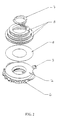
- a concentric foil heater 2 and a temperature monitoring device 3 are co-mounted within a housing 4 which is disposed around erbium spools 5 of an optical amplifier.
- a thermal interface 6 lies between the heater 2 and the erbium spools 5, allowing thermal communication between the heater 2 and the erbium spools 5.
- the heater, the thermal interface and erbium spools are held in position by a locking ring 7 which at one end engages within the erbium spools 5, and at the other end engages within the housing 4.
- Both the heater 2 and temperature monitoring device 3 are connected to a feedback circuit 11 which dynamically produces a control signal in response to the measured temperature of the erbium fiber dropping below a pre-determined threshold temperature, normally the nominal operating temperature.
- a signal is received by the heater to which activates it to heat the erbium fiber to a pre-determined maximum temperature.
- the actual pre-determined values are chosen based on the amplifier design and recognized nominal operating temperature of the amplifier.
- the temperature monitoring device 3 is integrated into the heater 2 in the form of an etched nickel wire, whereby the wire's resistance changes linearly with temperature.
- the wire forms part of the feedback circuit 11 as the wire's temperature dependence on resistivity is used in a 5V biased potential divider circuit for monitoring the temperature of the EDF.
- the temperature of the EDF in the spools 5 relative to the response of the wire 3 is determined by calibration.
- FIG. 3 shows a schematic diagram of the feedback circuit 11 where the signal from the potential divider is fed to an Analog to Digital converter (ADC) 12.
- ADC Analog to Digital converter
- the resulting digital signal (temperature signal) is input to a comparator 13 that compares the temperature signal against a preset value, Tset point (16), indicative of the threshold temperature. If the temperature signal is found to be less than the threshold temperature, the comparator sends a signal to a Proportional Integral compensator (PI compensator) 14 that applies error compensation, in respect of the heater driver circuit, to the signal.
- PI compensator Proportional Integral compensator
- the compensated signal is then input into a heater driver circuit for energizing the heater 2.
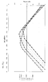
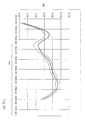
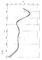
- Erbium fiber is inherently temperature dependent with respect to its gain spectrum. This property is illustrated in figure 6 which shows a part of a typical unfiltered game profile for EDF against wavelength for different temperatures. It can be seen that the gain spectrum varies over temperature, and that the gain spectrum is dominated by tilt effects especially at longer wavelengths. The rate of change of gain (dynamic gain variation) for the spectrum of figure 6 for different temperatures is shown in figure 7, and again this illustrates the inherent temperature dependence of erbium fiber.
- the characteristic shape of the gain deviation profile and hence gain ripple 1 for an EDF depends on the matching of the gain flattening filter profile 8 to the unfiltered gain spectrum 9. More particularly, it depends on the mismatch in shape of the two.
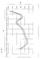
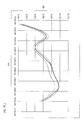
- Figures 5a, 5c, 5e and 5g illustrate the behaviour of gain ripple for different temperatures against the fiber length for different filter errors.
- Figures 5b, 5d, 5f and 5h respectively show the gain flattening filter profiles used to obtain the plots of figures 5a, 5c, 5e and 5g respectively.
- the plot characteristics vary according to the type of filter error.
- the plot of figure 5a exhibits a very large temperature dependence for a low loss red end filter error.
- the optimum EDF length is chosen for achieving minimum gain ripple over the operating temperature range imposed by the EDF spools 5.
- the operating temperature range in which the EDFA will be used i.e. the operating conditions.
- the optimum fiber length can be picked for maintaining minimal gain ripple over the temperature range the heater will be maintaining.
- most terrestrial optical communication systems with which the invention could be used have operating temperatures of about 35oC to 40oC at the nodes where the amplifier would be used.
- the optimum length selection for minimum gain ripple at a minimum temperature of 40oC can be determined by selecting the fiber length where the plot has a minimal gain value for 40oC and the temperature dependence of the plot is not too great, i.e. where the plot has "bottomed out". For example, for a low loss red end filter error, the plot shown in figure 5a "bottoms out” at about 14.3m to 14.4m and minimal gain occurs at a fiber length of 14.4m.
- the selected length of EDF is then used to load the spools 5 and is spliced into the optical amplifier. Afterwards, whilst in operation, the erbium spools 5 are temperature controlled using a temperature monitoring device 3 and heater 2, as previously described above, achieving efficient minimization of EDFA gain flatness over temperature.
- the optimum length of fiber is the total length of fiber to be used in the amplifier in order to achieve minimal gain deviation.
- Amplifiers suffer from losses due to the filters used in their construction, as well as the other components with which they are integrated in order that the amplifiers may be utilised in a communication system. If the losses are buried at the beginning of the amplifier, the noise performance of the amplifiers is degraded, and if the losses are buried at the end of the amplifier, then the output power of the amplifier is negatively affected. It is therefore more efficient to distribute losses throughout the whole of the amplifier, e.g. in the middle. So, rather than taking a fiber of optimal length and spooling it on to one mandrel, the optimal length of fiber is divided in to a number of sections, typically between two to four.
- Each section of fiber is spooled on to a corresponding mandrel and spliced in to the EDFA.
- the number and length of sections that the optimal length fiber is divided into depends on the specific amplifier, the communication system the amplifier is to be used in, and their associated loss characteristics.
- erbium doped fiber Although the description specifically mentions the use of erbium doped fiber, the present invention would work with other types of optical fiber, for example other types of doped optical fiber. Optical fibers that exhibit dynamic gain tilt characteristics would be particularly suited for use within the present invention. Such dopements could include co-dopements, for instance erbium doped fiber co-doped with bismuth, or erbium fiber co-doped with thulium. Use of these alternative optical fiber types as substantially described herein is considered to fall within the scope of the invention.
- the invention provides a method of amplifying a signal in an optical fiber in an optical fiber amplifier having a pre-determined operating temperature range, whereby the temperature of the fiber in the pre-determined operating temperature range is maintained, and the fiber has an optimal length so as to minimize gain ripple in the amplifier over the operating temperature range.
- the invention also provides an optical fiber amplifier having an optimal length of fiber, a heater and a temperature monitor both coupled thermally to the fiber. The temperature monitor is responsive to the temperature falling below the pre-determined operating temperature range of the amplifier to energize the heater, and is responsive to the temperature rising higher than the pre-determined operating temperature range of the amplifier to de-energize the heater.
Landscapes
- Physics & Mathematics (AREA)
- Electromagnetism (AREA)
- Engineering & Computer Science (AREA)
- Plasma & Fusion (AREA)
- Optics & Photonics (AREA)
- Microelectronics & Electronic Packaging (AREA)
- Lasers (AREA)
- Optical Communication System (AREA)
Abstract
Description
Claims (14)
- A method of amplifying a signal in an optical fiber in an optical fiber amplifier having a predetermined operating temperature range, said method comprising:maintaining the temperature of said optical fiber in said predetermined operating temperature range of said optical amplifier;said optical fiber having an optimal length such as to minimize gain ripple in said optical fiber amplifier over said operating temperature range.
- A method of manufacture of an optical fiber amplifier which includes a gain flattening filter, a length of optical fiber and a predetermined operating temperature range, said method comprising:calculating an optimal length of said optical fiber for minimum gain ripple over said operating temperature range of said optical fiber amplifier;and making said optical fiber amplifier from said optical fiber of said optimal length.
- A method according to claim 2 wherein the optimal length of optical fibre is calculated by determining a filter error function for said optical fibre amplifier and calculating from said filter error function the optimal length of optical fibre.
- A method according to claim 2 wherein the optimal length of optical fibre is calculated by:measuring the total passive loss of the optical fiber amplifier including said gain flattening filter, without the presence of optical fiber, at substantially nominal operating temperature;deriving an amplifier gain spectrum from a reference gain spectrum for said optical fiber and from said measurement of the total passive loss; andcalculating gain ripple against optical fiber length over temperature from said amplifier gain spectrum.
- A method of manufacture according to claim 4 further comprising measuring said reference gain spectrum for said optical fiber.
- A method according to any of the preceding claims wherein said optimal length of optical fiber comprises one or more spools (5) of optical fiber, the combined length of optical fiber in said spool or spools being substantially equal to said optimal length.
- A method according to any of the preceding claims wherein said optical fiber amplifier is an erbium doped fiber amplifier, and said optical fiber is erbium doped fiber.
- An optical fiber amplifier comprising:an optimal length of fiber, said optimal length being such as to minimize gain ripple in said amplifier over a predetermined operating temperature range of said amplifier; anda means for controlling the temperature of said optimal length of optical fiber.
- An optical fiber amplifier according to claim 8 wherein the means for controlling the temperature said optimal length of optical fibre includes a heater (2) and a temperature monitor device (3) both coupled thermally to said optimal length of optical fibre.
- An optical fibre amplifier according to claim 9 wherein the means for controlling the temperature of said optimal length of optical fibre further includes a temperature control circuit (11) responsive to said temperature monitor signaling a temperature below a first predetermined threshold temperature to energize said heater, and responsive to said temperature monitor signaling a temperature above a second predetermined threshold temperature, higher than said first threshold temperature, to de-energize the heater.
- An optical fiber amplifier according to any of claims 8-10 further comprising a gain flattening filter which has a filter error function, the optimal length of said optical fiber for minimum gain ripple over the operating temperature of the amplifier being a function of said filter error function.
- An optical fiber amplifier according to any of claims 8-11 wherein said optimal length of optical fiber comprises one or more spools (5) of optical fiber, the combined length of optical fiber in said spool or spools being substantially equal to said optimal length.
- An optical fiber amplifier according to any of claims 8-12 wherein said optical fiber amplifier is an erbium doped fiber amplifier and said optical fiber is erbium doped fiber.
- An optical system comprising:a transmitter for transmitting optical signals;a receiver for receiving said optical signals from said transmitter;a transmission channel connecting said transmitter to said receiver and along which said optical signals travel from said transmitter to said receiver; andan optical fiber amplifier for amplifying said optical signals as they travel along said transmission channel, said optical fiber amplifier comprising one or more spools (5) of optical fiber; the combined length of optical fiber in said spool or spools being substantially equal to an optimal length of said optical fiber, said optimal length being such as to minimize gain deviation in said amplifier over a predetermined operating temperature range of said amplifier; a heater means (2) for heating said optical fiber; and a monitor means (3) for monitoring the temperature of said optical fiber, and responsive to the temperature falling below the predetermined operating temperature range of said amplifier to energize heater means, and responsive to the temperature rising higher than said predetermined operating range of said amplifier to de-energize the heater means.
Applications Claiming Priority (2)
| Application Number | Priority Date | Filing Date | Title |
|---|---|---|---|
| US82158001A | 2001-03-29 | 2001-03-29 | |
| US821580 | 2001-03-29 |
Publications (2)
| Publication Number | Publication Date |
|---|---|
| EP1246322A2 true EP1246322A2 (en) | 2002-10-02 |
| EP1246322A3 EP1246322A3 (en) | 2005-01-26 |
Family
ID=25233748
Family Applications (1)
| Application Number | Title | Priority Date | Filing Date |
|---|---|---|---|
| EP02251194A Withdrawn EP1246322A3 (en) | 2001-03-29 | 2002-02-21 | Method and apparatus for minimising gain deviation in optical fibre amplifier |
Country Status (2)
| Country | Link |
|---|---|
| EP (1) | EP1246322A3 (en) |
| CA (1) | CA2374557A1 (en) |
Cited By (3)
| Publication number | Priority date | Publication date | Assignee | Title |
|---|---|---|---|---|
| WO2005078875A1 (en) * | 2004-02-10 | 2005-08-25 | Bookham Technology Plc | Optical amplifiers |
| US9184554B2 (en) | 2013-08-27 | 2015-11-10 | Lijie Qiao | Reducing thermal dependence of amplifier gain |
| US9680284B2 (en) | 2013-08-27 | 2017-06-13 | Lijie Qiao | Lessening variations of spectral characteristic of an optical device |
Family Cites Families (4)
| Publication number | Priority date | Publication date | Assignee | Title |
|---|---|---|---|---|
| FR2715481B1 (en) * | 1994-01-26 | 1996-02-16 | Mathilde Semenkoff | Optical fiber optic amplifier in doped fluorinated glass and method of manufacturing this amplifier. |
| US5920424A (en) * | 1997-02-18 | 1999-07-06 | Lucent Technologies Inc. | Article comprising a broadband optical fiber amplifier |
| US6166851A (en) * | 1998-12-29 | 2000-12-26 | Nortel Networks Limited | Optical amplifier manufacture |
| US6147795A (en) * | 1999-06-21 | 2000-11-14 | Lucent Technologies Inc. | Retrofit heater for erbium fiber in an erbium-doped fiber amplifier (EDFA) |
-
2002
- 2002-02-21 EP EP02251194A patent/EP1246322A3/en not_active Withdrawn
- 2002-03-05 CA CA002374557A patent/CA2374557A1/en not_active Abandoned
Cited By (7)
| Publication number | Priority date | Publication date | Assignee | Title |
|---|---|---|---|---|
| WO2005078875A1 (en) * | 2004-02-10 | 2005-08-25 | Bookham Technology Plc | Optical amplifiers |
| GB2424119A (en) * | 2004-02-10 | 2006-09-13 | Bookham Technology Plc | Optical amplifiers |
| GB2424119B (en) * | 2004-02-10 | 2007-09-12 | Bookham Technology Plc | Optical amplifiers |
| US7308182B2 (en) | 2004-02-10 | 2007-12-11 | Bookham Technology Plc | Optical amplifiers |
| CN100411260C (en) * | 2004-02-10 | 2008-08-13 | 波科海姆技术公共有限公司 | optical amplifier |
| US9184554B2 (en) | 2013-08-27 | 2015-11-10 | Lijie Qiao | Reducing thermal dependence of amplifier gain |
| US9680284B2 (en) | 2013-08-27 | 2017-06-13 | Lijie Qiao | Lessening variations of spectral characteristic of an optical device |
Also Published As
| Publication number | Publication date |
|---|---|
| EP1246322A3 (en) | 2005-01-26 |
| CA2374557A1 (en) | 2002-09-29 |
Similar Documents
| Publication | Publication Date | Title |
|---|---|---|
| US5982791A (en) | Wavelength tracking in adjustable optical systems | |
| US6545799B1 (en) | Method and apparatus for optical system link control | |
| US7081988B2 (en) | Optical amplifier, communication system and method for control tilt of a communication system | |
| US6731423B1 (en) | Optical amplifier and method | |
| US8320758B2 (en) | Channel monitor and method for estimating optical power | |
| JPH11119030A (en) | Dispersion compensating device | |
| US6337764B1 (en) | Optical fiber amplifier for controlling gain flatness | |
| JP2003535554A (en) | Optical transmission system | |
| US7202996B2 (en) | Optical amplifier | |
| US6525870B1 (en) | Method and system for controlling Raman gain flatness sensitivity to pump laser wavelength variation | |
| KR20010053319A (en) | Thermal tuning of optical amplifiers and use of same in wavelength division multiplexed systems | |
| CA2374557A1 (en) | Method and apparatus for minimising gain deviation in optical fibre amplifiers | |
| EP1675283B1 (en) | Method of controlling the gain of a raman amplifier | |
| CN1784849B (en) | Method for pre-emphasizing an optical multiplexed signal | |
| US9184554B2 (en) | Reducing thermal dependence of amplifier gain | |
| US20050052731A1 (en) | Optical amplifier control in wdm communications systems | |
| KR100251557B1 (en) | Optical fiber amplifier | |
| US7495825B2 (en) | Integration of a gain equalization filter in a gain medium | |
| EP1456977A2 (en) | Method and apparatus for optical wdm signal transmission using raman amplification | |
| US7130110B2 (en) | Temperature control in an optical amplification system | |
| EP1313235B1 (en) | Optical amplifier and optical communication system including the same | |
| US7236700B1 (en) | Scalable and exchangeable erbium doped fiber amplifier for DWDM | |
| JP2013523037A (en) | ASE correction of optical amplifier | |
| KR100367085B1 (en) | Device for Compensation of Loss Variation in Optical Transmission Line | |
| JP2004117568A (en) | Gain equalizer manufacturing method, gain equalizer, and optical amplifier |
Legal Events
| Date | Code | Title | Description |
|---|---|---|---|
| PUAI | Public reference made under article 153(3) epc to a published international application that has entered the european phase |
Free format text: ORIGINAL CODE: 0009012 |
|
| AK | Designated contracting states |
Kind code of ref document: A2 Designated state(s): AT BE CH CY DE DK ES FI FR GB GR IE IT LI LU MC NL PT SE TR |
|
| AX | Request for extension of the european patent |
Free format text: AL;LT;LV;MK;RO;SI |
|
| RAP1 | Party data changed (applicant data changed or rights of an application transferred) |
Owner name: BOOKHAM TECHNOLOGY PLC |
|
| 111Z | Information provided on other rights and legal means of execution |
Free format text: ATBECHCYDEDKESFIFRGBGRIEITLILUMCNLPTSETR Effective date: 20031030 |
|
| PUAL | Search report despatched |
Free format text: ORIGINAL CODE: 0009013 |
|
| STAA | Information on the status of an ep patent application or granted ep patent |
Free format text: STATUS: THE APPLICATION IS DEEMED TO BE WITHDRAWN |
|
| AK | Designated contracting states |
Kind code of ref document: A3 Designated state(s): AT BE CH CY DE DK ES FI FR GB GR IE IT LI LU MC NL PT SE TR |
|
| AX | Request for extension of the european patent |
Extension state: AL LT LV MK RO SI |
|
| RIC1 | Information provided on ipc code assigned before grant |
Ipc: 7H 04B 10/17 B Ipc: 7H 01S 3/067 A |
|
| 18D | Application deemed to be withdrawn |
Effective date: 20040831 |