EP1246221A1 - Methods of producing shrink-sealed metal halide arc tubes - Google Patents
Methods of producing shrink-sealed metal halide arc tubes Download PDFInfo
- Publication number
- EP1246221A1 EP1246221A1 EP02252124A EP02252124A EP1246221A1 EP 1246221 A1 EP1246221 A1 EP 1246221A1 EP 02252124 A EP02252124 A EP 02252124A EP 02252124 A EP02252124 A EP 02252124A EP 1246221 A1 EP1246221 A1 EP 1246221A1
- Authority
- EP
- European Patent Office
- Prior art keywords
- arm
- seal
- tube body
- arc tube
- electrode assembly
- Prior art date
- Legal status (The legal status is an assumption and is not a legal conclusion. Google has not performed a legal analysis and makes no representation as to the accuracy of the status listed.)
- Withdrawn
Links
Images
Classifications
-
- H—ELECTRICITY
- H01—ELECTRIC ELEMENTS
- H01J—ELECTRIC DISCHARGE TUBES OR DISCHARGE LAMPS
- H01J9/00—Apparatus or processes specially adapted for the manufacture, installation, removal, maintenance of electric discharge tubes, discharge lamps, or parts thereof; Recovery of material from discharge tubes or lamps
- H01J9/24—Manufacture or joining of vessels, leading-in conductors or bases
- H01J9/32—Sealing leading-in conductors
- H01J9/323—Sealing leading-in conductors into a discharge lamp or a gas-filled discharge device
Definitions
- the invention relates to a method of making metal halide arc tubes, more specifically arc tubes for use in metal halide arc lamps
- Shrink sealing refers to the process of making metal halide arc tubes and lamps without the use of a separate exhaust tube for pressurizing and depressurizing the tube and for inserting vaporizable doses of mercury and halide compounds.
- the arc tube body material typically quartz, is given an internal pressure lower than the ambient atmospheric pressure and is then heated and allowed to shrink down on an electrode assembly, thus capturing the electrode in the desired position.
- the mercury and halide doses are inserted, and then a shrink seal is formed near the midsection containing the doses. Formation of the shrink seal near the newly inserted doses may cause them to vaporize and contaminate the vacuum system. It would be desirable to minimize the possibility of halide vaporization and resultant contamination of the vacuum system. Another contamination problem may arise if hydrocarbons from the vacuum system enter the arc tube body and interfere with the subsequent function of the lamp. It would thus be desirable to minimize the possibility of hydrocarbon contamination of the arc tube body from the vacuum system.
- a reflective coating is often applied to the exterior of the arc tube body.
- the electrode leads should be protected during application of the coating so as to remain unfouled.
- a method of producing a metal halide arc tube comprises the steps of providing an arc tube body having first and second ends; inserting a first electrode assembly and a second electrode assembly into the arc tube body, and creating first, second, third and fourth seals in the arc tube body.
- Each seal is formed by heating the arc tube body at a desired location while maintaining a gas pressure inside the arc tube body lower than the pressure outside the arc tube body. A first portion including the first end and one of the seals is removed, and a second portion including the second end and another of the seals is removed.
- an aspect of the method according to the invention begins with the provision of a pre-formed quartz arc tube body 10 having a bulbous midsection 12 and two arms 14, 16, each projecting in opposite directions from the midsection. Each arm has an outer end 15, 17.
- the arc tube body is seized in the headstock and tailstock of a lathe (not shown) having the capacity to rotate the arc tube body on its axis, evacuate the arc tube body, apply heat sufficient to melt the arc tube body, and supply appropriate fill gases to the arc tube body.
- Electrode assemblies 18, 20 are inserted into the arc tube body.
- Each electrode assembly has a molybdenum foil 32, a spring clip 34 attached to the foil, a tungsten shank 36 attached to the molybdenum foil, and a coil 38 attached to the tip of the shank.
- the spring clip and shank each project in opposite directions from the foil.
- Each electrode assembly is positioned in an arm with its spring clip projecting toward the outer end of the arm.
- the electrode assemblies are placed in the arc tube body so that the space between the coils is in the arc chamber 13, preferably defined by the bulbous midsection 12, and the distance between the coils is appropriate for the size and rating of the lamp.
- the arc chamber is preferably essentially centrally located in the arc tube body, between the electrode assemblies.
- the spring clip serves to temporarily hold the electrode assembly in place until the electrode assembly is sealed in place in the arc tube body.
- a first seal 42 is made by simultaneously rotating, evacuating, and heating the tube until the quartz melts and collapses.
- This seal is made, preferably between the molybdenum foil 32 of electrode assembly 18 and the adjacent outer end 15 of the arm 14 seized in the tailstock of the lathe, more preferably between the electrode assembly 18 and the adjacent outer end 15 of the arm 14 seized in the tailstock of the lathe.
- a vacuum is drawn from a tail stock pump while the head stock is blanked off. After this first seal is formed the interior of the arc tube body is protected from contaminants originating from the tail stock vacuum system.
- a second seal 44 is formed to encompass a central portion of electrode assembly 18, preferably at the foil 32 of the electrode assembly 18, in the same arm 14 as the first seal 42.
- Forming a seal at a central portion of the electrode assembly such as the molybdenum foil ensures that part of the electrode assembly will extend from each side of the seal, allowing passage of electricity through the seal via the electrode assembly.
- the second seal is also formed by rotating, evacuating and heating the tube until the quartz melts and collapses. The vacuum is drawn from the headstock through outer end 17 during the formation of the second seal. Following the formation of the second seal, doses of halide compound 46 and of mercury 48 are inserted into the arc chamber, as shown in Fig. 4.
- the halide doses typically comprise a mixture of the bromides or iodides of sodium, scandium, and thorium, but may contain any of the commonly used halides for high intensity discharge lamps. These include iodides and bromides of thallium, dysprosium, holmium, thulium, cerium, cesium, and calcium.
- the insertion of the doses is generally performed with the assistance of gravity without moving the already-positioned electrode assemblies. This is best done by placing the arc tube body with its long axis in a vertical position with the open arm facing upward, and then releasing the doses into the arc tube body from a position above the electrode. Even if the doses strike the electrode assembly, they will generally move downward past the assembly and into the bulbous midsection without substantially changing the position of either electrode assembly. This is important, as any substantial change in the position of the electrode assembly which would require repositioning of the electrode assembly to ensure proper function of the arc tube.
- the use of a small halide pellet allows sufficient clearance for the pellet to move past the electrode.
- the doses can be introduced separately, or in combination.
- the arc tube body is re-pressurized with a fill gas through outer end 17.
- Typical fill gases are argon, krypton, xenon, or mixtures thereof.
- Typical fill gas pressures are 20-500 torr.
- a third seal 50 is made, preferably between the molybdenum foil 32 of electrode assembly 20 and the outer end 17 of the arm 16, more preferably between the electrode assembly 20 and the outer end 17 of the arm 16.
- This seal is also made by heating and rotating the arc tube body along its axis. Because the pressure in the arc tube body is less than the ambient pressure, the quartz will collapse to form the seal when heated.
- the seal 50 By making the seal 50 at a distance from the arc chamber 13, rather than at foil 20, less heat is transferred to the halide doses 46 and vaporization of the halide doses is reduced or avoided. Thus contamination of the headstock by halide vapor escaping through outer end 17 is also reduced or avoided.
- a fourth seal 52 is made at a central portion of the electrode assembly 32, preferably at the foil 32 of the electrode assembly 20 in the same arm 16 as the third seal 50.
- This seal is also formed by rotating and heating the tube until the quartz melts and collapses.
- the sub-atmospheric pressure of the fill gas in the arc tube body will result in the quartz tube collapsing when softened by heating, as it did during formation of the third seal.
- cooling of the tube may be necessary to maintain the gas pressure in the arc tube body below ambient pressure.
- an outer coating may be applied to the arc tube body.
- Outer coatings are generally used to reflect infrared radiation back into the arc chamber. This helps to ensure that a sufficiently high temperature is maintained on the interior of the arc chamber. Typically the central portion of the bulbous midsection will be masked off to prevent deposition of the coating in that region.
- an arc tube body 10 is shown with a coating 54 substantially covering the surface except for a central portion of the bulbous midsection 12.
- the coating is typically a single or multiple layer thin film of an alumina material, although other known coatings such as zirconia, tantala, silica, titania, or combinations thereof may be used. Seals 42 and 50 ensure that the coating is not deposited on spring clips 34 of electrode assemblies 18 and 20.
- the ends of the arc tube body are removed, resulting in an arc tube body with two seals and two outer ends 60, 62.
- the spring clips 34 are trimmed, leaving two electrode leads 56, 58 for connection to a source of electrical energy. By following this procedure, contamination of the leads by the coating process is avoided.
Landscapes
- Engineering & Computer Science (AREA)
- Manufacturing & Machinery (AREA)
- Vessels And Coating Films For Discharge Lamps (AREA)
- Manufacture Of Electron Tubes, Discharge Lamp Vessels, Lead-In Wires, And The Like (AREA)
Abstract
A method of producing a metal halide arc tube (10) is provided, in which four seals (42,44,50,52) are made in the arc tube body (10). Electrode assemblies (18,20) are inserted and the arc tube body (10) is sealed (42) at one end (15), blocking contamination from that end. A second seal (44) encloses the electrode assembly (18) nearer the first seal (42). Halide (46) and mercury (48) doses are introduced into the central arc chamber (13) through the open end of the arc tube body (10). A third seal (50) is made at the open end at a distance from the arc chamber (13), reducing vaporization of the doses and contamination of equipment. A fourth seal (52) encloses the electrode assembly (20) nearer the third seal (50). The electrode assemblies (18,20) are thus protected and a reflective coating (54) may be applied without electrode contamination. The ends (15,17) of the arc tube body (10) are then removed, exposing the electrodes.
Description
- The invention relates to a method of making metal halide arc tubes, more specifically arc tubes for use in metal halide arc lamps
- Shrink sealing refers to the process of making metal halide arc tubes and lamps without the use of a separate exhaust tube for pressurizing and depressurizing the tube and for inserting vaporizable doses of mercury and halide compounds. For each seal, the arc tube body material, typically quartz, is given an internal pressure lower than the ambient atmospheric pressure and is then heated and allowed to shrink down on an electrode assembly, thus capturing the electrode in the desired position.
- Typically the mercury and halide doses are inserted, and then a shrink seal is formed near the midsection containing the doses. Formation of the shrink seal near the newly inserted doses may cause them to vaporize and contaminate the vacuum system. It would be desirable to minimize the possibility of halide vaporization and resultant contamination of the vacuum system. Another contamination problem may arise if hydrocarbons from the vacuum system enter the arc tube body and interfere with the subsequent function of the lamp. It would thus be desirable to minimize the possibility of hydrocarbon contamination of the arc tube body from the vacuum system.
- After the halide doses and electrodes are sealed in place, a reflective coating is often applied to the exterior of the arc tube body. The electrode leads should be protected during application of the coating so as to remain unfouled.
- According to the present invention, a method of producing a metal halide arc tube is provided. The method comprises the steps of providing an arc tube body having first and second ends; inserting a first electrode assembly and a second electrode assembly into the arc tube body, and creating first, second, third and fourth seals in the arc tube body. Each seal is formed by heating the arc tube body at a desired location while maintaining a gas pressure inside the arc tube body lower than the pressure outside the arc tube body. A first portion including the first end and one of the seals is removed, and a second portion including the second end and another of the seals is removed.
- An embodiment of the invention will now be described, by way of example, with reference to the accompanying drawings, in which:
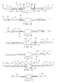
- Fig. 1 is an elevation of an arc tube body following insertion of electrodes.
- Fig. 2 is an elevation of an arc tube body following creation of a first seal between an electrode and an outer end of an arm of the arc tube body.
- Fig. 3 is an elevation of an arc tube body following creation of a second seal encompassing an electrode.
- Fig. 4 is an elevation of an arc tube body following insertion of mercury and halide doses and creation of a third seal between an electrode and an outer end of an arm of the arc tube body.
- Fig. 5 is an elevation of an arc tube body following creation of a fourth seal encompassing an electrode.
- Fig. 6 is an elevation of an arc tube body following application of a coating.
- Fig. 7 is an elevation of an arc tube body following removal of the outer parts of the arms and trimming of the electrode assembly leads.
-
- In the description that follows and in the claims, when a preferred range, such as 5-25, is given, this means preferably at least 5, and separately and independently, preferably not more than 25.Referring to Fig. 1, an aspect of the method according to the invention begins with the provision of a pre-formed quartz
arc tube body 10 having abulbous midsection 12 and twoarms outer end Electrode assemblies molybdenum foil 32, aspring clip 34 attached to the foil, atungsten shank 36 attached to the molybdenum foil, and acoil 38 attached to the tip of the shank. The spring clip and shank each project in opposite directions from the foil. Each electrode assembly is positioned in an arm with its spring clip projecting toward the outer end of the arm. The electrode assemblies are placed in the arc tube body so that the space between the coils is in thearc chamber 13, preferably defined by thebulbous midsection 12, and the distance between the coils is appropriate for the size and rating of the lamp. The arc chamber is preferably essentially centrally located in the arc tube body, between the electrode assemblies. The spring clip serves to temporarily hold the electrode assembly in place until the electrode assembly is sealed in place in the arc tube body. - Referring to Fig. 2, a
first seal 42 is made by simultaneously rotating, evacuating, and heating the tube until the quartz melts and collapses. This seal is made, preferably between themolybdenum foil 32 ofelectrode assembly 18 and the adjacentouter end 15 of thearm 14 seized in the tailstock of the lathe, more preferably between theelectrode assembly 18 and the adjacentouter end 15 of thearm 14 seized in the tailstock of the lathe. A vacuum is drawn from a tail stock pump while the head stock is blanked off. After this first seal is formed the interior of the arc tube body is protected from contaminants originating from the tail stock vacuum system. - Referring to Fig. 3, a
second seal 44 is formed to encompass a central portion ofelectrode assembly 18, preferably at thefoil 32 of theelectrode assembly 18, in thesame arm 14 as thefirst seal 42. Forming a seal at a central portion of the electrode assembly such as the molybdenum foil ensures that part of the electrode assembly will extend from each side of the seal, allowing passage of electricity through the seal via the electrode assembly. The second seal is also formed by rotating, evacuating and heating the tube until the quartz melts and collapses. The vacuum is drawn from the headstock throughouter end 17 during the formation of the second seal. Following the formation of the second seal, doses ofhalide compound 46 and ofmercury 48 are inserted into the arc chamber, as shown in Fig. 4. The halide doses typically comprise a mixture of the bromides or iodides of sodium, scandium, and thorium, but may contain any of the commonly used halides for high intensity discharge lamps. These include iodides and bromides of thallium, dysprosium, holmium, thulium, cerium, cesium, and calcium. - The insertion of the doses is generally performed with the assistance of gravity without moving the already-positioned electrode assemblies. This is best done by placing the arc tube body with its long axis in a vertical position with the open arm facing upward, and then releasing the doses into the arc tube body from a position above the electrode. Even if the doses strike the electrode assembly, they will generally move downward past the assembly and into the bulbous midsection without substantially changing the position of either electrode assembly. This is important, as any substantial change in the position of the electrode assembly which would require repositioning of the electrode assembly to ensure proper function of the arc tube. The use of a small halide pellet allows sufficient clearance for the pellet to move past the electrode. The doses can be introduced separately, or in combination.
- Following insertion of the doses, the arc tube body is re-pressurized with a fill gas through
outer end 17. Typical fill gases are argon, krypton, xenon, or mixtures thereof. Typical fill gas pressures are 20-500 torr. - It is desirable to maintain sub-atmospheric pressure in the arc tube body during the formation of the seals. During operation of the lamp the temperature and pressure of the fill gas will rise. Nevertheless, if a higher operating pressure is desired than can be provided by introducing a subatmospheric gas fill at ambient temperature, then the arc tube body, the gas fill, or both may be cooled during pressurization. This will allow more gas to be introduced into the arc tube body, while maintaining sub-atmospheric gas pressure in the arc tube body during manufacture.
- Following insertion of the doses and pressurization, a
third seal 50 is made, preferably between themolybdenum foil 32 ofelectrode assembly 20 and theouter end 17 of thearm 16, more preferably between theelectrode assembly 20 and theouter end 17 of thearm 16. This seal is also made by heating and rotating the arc tube body along its axis. Because the pressure in the arc tube body is less than the ambient pressure, the quartz will collapse to form the seal when heated. By making theseal 50 at a distance from thearc chamber 13, rather than atfoil 20, less heat is transferred to thehalide doses 46 and vaporization of the halide doses is reduced or avoided. Thus contamination of the headstock by halide vapor escaping throughouter end 17 is also reduced or avoided. - Referring to Fig. 5, a
fourth seal 52 is made at a central portion of theelectrode assembly 32, preferably at thefoil 32 of theelectrode assembly 20 in thesame arm 16 as thethird seal 50. This seal is also formed by rotating and heating the tube until the quartz melts and collapses. The sub-atmospheric pressure of the fill gas in the arc tube body will result in the quartz tube collapsing when softened by heating, as it did during formation of the third seal. As with formation of the third seal, cooling of the tube may be necessary to maintain the gas pressure in the arc tube body below ambient pressure. - Following formation of the fourth seal, an outer coating may be applied to the arc tube body. Outer coatings are generally used to reflect infrared radiation back into the arc chamber. This helps to ensure that a sufficiently high temperature is maintained on the interior of the arc chamber. Typically the central portion of the bulbous midsection will be masked off to prevent deposition of the coating in that region. In Fig. 6, an
arc tube body 10 is shown with acoating 54 substantially covering the surface except for a central portion of thebulbous midsection 12. The coating is typically a single or multiple layer thin film of an alumina material, although other known coatings such as zirconia, tantala, silica, titania, or combinations thereof may be used.Seals electrode assemblies - After the coating is deposited on the arc tube body, the ends of the arc tube body are removed, resulting in an arc tube body with two seals and two
outer ends - For completeness, various aspects of the invention are set out in the following numbered clauses:
- 1. A method of producing a metal halide arc tube comprising the steps of providing an arc tube body (10) having first and second ends (15,17); inserting a first electrode assembly and a second electrode assembly (18,20) into the arc tube body; creating first, second, third and fourth seals (42,44,50,52) in the arc tube body (10), each seal being formed by heating the arc tube body (10) at a desired location while maintaining a gas pressure inside the arc tube body (10) lower than the pressure outside the arc tube body (10); removing a first portion of the arc tube body (10), the first portion comprising the first end (15) and one of the seals (42,44,50,52); and removing a second portion of the arc tube body (10), the second portion comprising the second end (17) and another of the seals (42,44,50,52).
- 2. A method according to clause 1, wherein the first seal (42) is formed before the second, third, and fourth seals (44,50,52), the first seal (42) being formed between a central portion of the first electrode (18) assembly and the first end (15).
- 3. A method according to clause 2, further comprising the step of maintaining a reduced gas pressure inside the arc tube body (10) while forming the first seal (42), said reduced gas pressure being maintained by blanking off the second end (17) and evacuating gas from the first end (15).
- 4. A method according to clause 2, further comprising the step of positioning the first electrode assembly (18) between the first end (15) and an arc chamber (13), said arc chamber (13) being essentially centrally located in said arc tube body (10).
- 5. A method according to clause 2, wherein the second seal (44) is formed before the third and fourth seals (50,52), the second seal (44) being formed so as to encompass a central portion of the first electrode assembly (18).
- 6. A method according to clause 5, further comprising the step of positioning the first electrode assembly (18) between the first end (15) and an arc chamber (13), said arc chamber (13) being essentially centrally located in said arc tube body (10).
- 7. A method according to clause 5, further comprising the step of maintaining a reduced gas pressure inside the arc tube body (10) while forming the second seal (44) by evacuating gas from the second end (17).
- 8. A method according to clause 5, wherein the third seal (50) is formed before the fourth seal (52) is formed, the third seal (50) being formed between a central portion of the second electrode (20) and the second end (17).
- 9. A method according to clause 8, further comprising the step of positioning the second electrode (20) between the first electrode (18) and the second end (17).
- 10. A method according to clause 8, further comprising the step of forming the fourth seal (52) so as to encompass a central portion of the second electrode assembly (20).
- 11. A method according to clause 1, comprising the further step of placing a dose of mercury (48) and a dose of halide compound (46) in the tube (10) after forming the second seal (44).
- 12. A method according to clause 11, wherein the doses of mercury (48) and of halide compound (46) are placed in the arc tube body (10) after the first and second electrode assemblies (18,20) are placed in the arc tube body (10).
- 13. A method according to
clause 12, wherein the doses of mercury (48) and of halide compound (46) are placed in the arc tube body (10) without substantially changing the position of either electrode assembly (18,20). - 14. A method according to clause 1, wherein a reduced gas pressure in the arc tube body (10) is maintained while forming the third seal (50) by introduction of a fill gas at a pressure of 20-500 torr.
- 15. A method according to clause 1, wherein the arc tube body (10) is a quartz arc tube body.
- 16. A method of producing a metal halide arc tube comprising the steps of providing a quartz tube (10) comprising a bulbous section (12), a first arm (14) and a second arm (16), each arm extending from the bulbous section (12), and each arm having an outer end (15,17); inserting a first electrode assembly (18) and a second electrode assembly (20) into the quartz tube (10) so that the electrode assemblies (18,20) are a predetermined distance apart from each other and one electrode assembly (18,20) is disposed in each arm (14,16), each electrode assembly (18,20) comprising a foil (32), a spring clip (34) attached to the foil (32) and extending away from the bulbous section (12), a shank (36) attached to the foil (32) and extending toward the bulbous section (12), and a coil (38) attached to the shank (36); reducing the gas pressure in the quartz tube (10) by evacuating gas from the first arm's (14) outer end (15) while blanking off the second arm's (16) outer end (17); creating a first seal (42) in the first arm (14) of the quartz tube (10) between the electrode assembly (18,20) disposed in the first arm (14) and the outer end (15) of the first arm (14) by rotating and heating the quartz tube (10) at the desired location until the quartz tube (10) melts and collapses; then evacuating gas from the second arm's (16) outer end (17) to reduce pressure in the quartz tube (10) between the first seal (42) and the second arm's (16) outer end (17); creating a second seal (44) in the first arm (14) at the location of the foil (32) of the electrode assembly (18,20) in the first arm (14) by rotating and heating the quartz tube (10) until the quartz tube (10) melts and collapses on the foil (32); placing a dose of mercury (48) and a dose of halide compound (46) into the bulbous section (12); pressurizing the quartz tube (10) between the second seal (44) and the second arm's (16) outer end (17) with a fill gas to a pressure of 20-500 torr; creating a third seal (50) in the second arm (16) of the quartz tube (10) between the electrode assembly (18,20) disposed in the second arm (16) and the outer end (17) of the second arm (16) by rotating and heating the quartz tube (10) at the desired location until the quartz tube (10) melts and collapses; creating a fourth seal (52) in the second arm (16) of the quartz tube (10) at the location of the foil (32) by rotating and heating the quartz tube (10) at the desired location until the quartz tube (10) melts and collapses; applying an external coating (54) to the quartz tube (10); removing a section of each arm (14,16) between the outer end (15,17) of the arm and the foil (32); and trimming each spring clip (34) to a desired length.
-
Claims (10)
- A method of producing a metal halide arc tube comprising the steps of providing an arc tube body (10) having first and second ends (15,17); inserting a first electrode assembly and a second electrode assembly (18,20) into the arc tube body; creating first, second, third and fourth seals (42,44,50,52) in the arc tube body (10), each seal being formed by heating the arc tube body (10) at a desired location while maintaining a gas pressure inside the arc tube body (10) lower than the pressure outside the arc tube body (10); removing a first portion of the arc tube body (10), the first portion comprising the first end (15) and one of the seals (42,44,50,52); and removing a second portion of the arc tube body (10), the second portion comprising the second end (17) and another of the seals (42,44,50,52).
- A method according to claim 1, wherein the first seal (42) is formed before the second, third, and fourth seals (44,50,52), the first seal (42) being formed between a central portion of the first electrode (18) assembly and the first end (15).
- A method according to claim 2, further comprising the step of maintaining a reduced gas pressure inside the arc tube body (10) while forming the first seal (42), said reduced gas pressure being maintained by blanking off the second end (17) and evacuating gas from the first end (15).
- A method according to claim 2, further comprising the step of positioning the first electrode assembly (18) between the first end (15) and an arc chamber (13), said arc chamber (13) being essentially centrally located in said arc tube body (10).
- A method according to claim 2, wherein the second seal (44) is formed before the third and fourth seals (50,52), the second seal (44) being formed so as to encompass a central portion of the first electrode assembly (18).
- A method according to claim 1, comprising the further step of placing a dose of mercury (48) and a dose of halide compound (46) in the tube (10) after forming the second seal (44).
- A method according to claim 6, wherein the doses of mercury (48) and of halide compound (46) are placed in the arc tube body (10) after the first and second electrode assemblies (18,20) are placed in the arc tube body (10).
- A method according to claim 1, wherein a reduced gas pressure in the arc tube body (10) is maintained while forming the third seal (50) by introduction of a fill gas at a pressure of 20-500 torr.
- A method according to claim 1, wherein the arc tube body (10) is a quartz arc tube body.
- A method of producing a metal halide arc tube comprising the steps of providing a quartz tube (10) comprising a bulbous section (12), a first arm (14) and a second arm (16), each arm extending from the bulbous section (12), and each arm having an outer end (15,17); inserting a first electrode assembly (18) and a second electrode assembly (20) into the quartz tube (10) so that the electrode assemblies (18,20) are a predetermined distance apart from each other and one electrode assembly (18,20) is disposed in each arm (14,16), each electrode assembly (18,20) comprising a foil (32), a spring clip (34) attached to the foil (32) and extending away from the bulbous section (12), a shank (36) attached to the foil (32) and extending toward the bulbous section (12), and a coil (38) attached to the shank (36); reducing the gas pressure in the quartz tube (10) by evacuating gas from the first arm's (14) outer end (15) while blanking off the second arm's (16) outer end (17); creating a first seal (42) in the first arm (14) of the quartz tube (10) between the electrode assembly (18,20) disposed in the first arm (14) and the outer end (15) of the first arm (14) by rotating and heating the quartz tube (10) at the desired location until the quartz tube (10) melts and collapses; then evacuating gas from the second arm's (16) outer end (17) to reduce pressure in the quartz tube (10) between the first seal (42) and the second arm's (16) outer end (17); creating a second seal (44) in the first arm (14) at the location of the foil (32) of the electrode assembly (18,20) in the first arm (14) by rotating and heating the quartz tube (10) until the quartz tube (10) melts and collapses on the foil (32); placing a dose of mercury (48) and a dose of halide compound (46) into the bulbous section (12); pressurizing the quartz tube (10) between the second seal (44) and the second arm's (16) outer end (17) with a fill gas to a pressure of 20-500 torr; creating a third seal (50) in the second arm (16) of the quartz tube (10) between the electrode assembly (18,20) disposed in the second arm (16) and the outer end (17) of the second arm (16) by rotating and heating the quartz tube (10) at the desired location until the quartz tube (10) melts and collapses; creating a fourth seal (52) in the second arm (16) of the quartz tube (10) at the location of the foil (32) by rotating and heating the quartz tube (10) at the desired location until the quartz tube (10) melts and collapses; applying an external coating (54) to the quartz tube (10); removing a section of each arm (14,16) between the outer end (15,17) of the arm and the foil (32); and trimming each spring clip (34) to a desired length.
Applications Claiming Priority (2)
| Application Number | Priority Date | Filing Date | Title |
|---|---|---|---|
| US817653 | 2001-03-26 | ||
| US09/817,653 US20010024089A1 (en) | 2000-03-23 | 2001-03-26 | Outer seals for shrink-sealed metal halide arc tubes |
Publications (1)
| Publication Number | Publication Date |
|---|---|
| EP1246221A1 true EP1246221A1 (en) | 2002-10-02 |
Family
ID=25223563
Family Applications (1)
| Application Number | Title | Priority Date | Filing Date |
|---|---|---|---|
| EP02252124A Withdrawn EP1246221A1 (en) | 2001-03-26 | 2002-03-25 | Methods of producing shrink-sealed metal halide arc tubes |
Country Status (3)
| Country | Link |
|---|---|
| US (1) | US20010024089A1 (en) |
| EP (1) | EP1246221A1 (en) |
| JP (1) | JP2002352716A (en) |
Families Citing this family (1)
| Publication number | Priority date | Publication date | Assignee | Title |
|---|---|---|---|---|
| US20060226783A1 (en) * | 2004-07-13 | 2006-10-12 | Abbas Lamouri | Krypton metal halide lamps |
Citations (6)
| Publication number | Priority date | Publication date | Assignee | Title |
|---|---|---|---|---|
| US4810932A (en) * | 1985-11-15 | 1989-03-07 | General Electric Company | Tungsten-halogen incandescent and metal vapor discharge lamps and processes of making such |
| US4891555A (en) * | 1985-11-15 | 1990-01-02 | General Electric Company | Metal vapor discharge lamps |
| EP0374677A2 (en) * | 1988-12-19 | 1990-06-27 | Patent-Treuhand-Gesellschaft für elektrische Glühlampen mbH | Method for producing a two-sided high-pressure discharge lamp |
| US5045748A (en) * | 1985-11-15 | 1991-09-03 | General Electric Company | Tungsten-halogen incandescent and metal vapor discharge lamps and processes of making such |
| US5087218A (en) * | 1985-11-15 | 1992-02-11 | General Electric Company | Incandesent lamps and processes for making same |
| EP0962955A2 (en) * | 1998-05-25 | 1999-12-08 | Matsushita Electric Industrial Co., Ltd. | Lamp and manufacturing method thereof |
-
2001
- 2001-03-26 US US09/817,653 patent/US20010024089A1/en not_active Abandoned
-
2002
- 2002-03-25 EP EP02252124A patent/EP1246221A1/en not_active Withdrawn
- 2002-03-25 JP JP2002082197A patent/JP2002352716A/en not_active Withdrawn
Patent Citations (6)
| Publication number | Priority date | Publication date | Assignee | Title |
|---|---|---|---|---|
| US4810932A (en) * | 1985-11-15 | 1989-03-07 | General Electric Company | Tungsten-halogen incandescent and metal vapor discharge lamps and processes of making such |
| US4891555A (en) * | 1985-11-15 | 1990-01-02 | General Electric Company | Metal vapor discharge lamps |
| US5045748A (en) * | 1985-11-15 | 1991-09-03 | General Electric Company | Tungsten-halogen incandescent and metal vapor discharge lamps and processes of making such |
| US5087218A (en) * | 1985-11-15 | 1992-02-11 | General Electric Company | Incandesent lamps and processes for making same |
| EP0374677A2 (en) * | 1988-12-19 | 1990-06-27 | Patent-Treuhand-Gesellschaft für elektrische Glühlampen mbH | Method for producing a two-sided high-pressure discharge lamp |
| EP0962955A2 (en) * | 1998-05-25 | 1999-12-08 | Matsushita Electric Industrial Co., Ltd. | Lamp and manufacturing method thereof |
Also Published As
| Publication number | Publication date |
|---|---|
| JP2002352716A (en) | 2002-12-06 |
| US20010024089A1 (en) | 2001-09-27 |
Similar Documents
| Publication | Publication Date | Title |
|---|---|---|
| EP0903771B1 (en) | High-pressure discharge lamp and method for manufacturing the same | |
| JPH09185944A (en) | Manufacture of low pressure mercury discharge lamp and low pressure mercury discharge lamp | |
| JPH07282719A (en) | High-pressure gas electric-discharge lamp | |
| CN100538966C (en) | Manufacturing is provided with the method for the electric light of outer bulb | |
| US5176558A (en) | Methods for removing contaminants from arc discharge lamps | |
| JPH04220941A (en) | Metal halide thin film for protection of high-pressure electrodeless discharge lamp | |
| EP1246221A1 (en) | Methods of producing shrink-sealed metal halide arc tubes | |
| EP0410512B1 (en) | Electric lamp | |
| EP1390963A1 (en) | High intensity discharge lamps, arc tubes and methods of manufacture | |
| US4746316A (en) | Method for manufacturing a luminous tube for discharge lamp | |
| US20070210714A1 (en) | Glass tubes for lamps, method for manufacturing the same, and lamps | |
| US7432657B2 (en) | Ceramic lamp having shielded niobium end cap and systems and methods therewith | |
| JPH11162409A (en) | High pressure discharge lamp and method of manufacturing the same | |
| EP1168408A1 (en) | Method for producing a discharge lamp and discharge lamp | |
| CN100550258C (en) | High intensity discharge lamp, arc tube and method of manufacturing the same | |
| EP0093383A2 (en) | Gas lamp and method of manufacture | |
| JPH04248247A (en) | Protective film for high-luminous intensity metal halide discharge lamp | |
| EP0410511A1 (en) | Electric lamp | |
| JP2003109504A (en) | Method for manufacturing high pressure discharge lamp and high pressure discharge lamp | |
| JPH01120728A (en) | Manufacture of metal vapor discharge lamp | |
| JP3319265B2 (en) | High pressure metal vapor discharge lamp | |
| JP4507040B2 (en) | Metal vapor discharge lamp and method for producing metal vapor discharge lamp | |
| US20040014391A1 (en) | High intensity discharge lamps, arc tubes and methods of manufacture | |
| JPH0687403B2 (en) | Method for manufacturing low-pressure mercury vapor discharge lamp | |
| JP2009211914A (en) | Method of manufacturing discharge lamp |
Legal Events
| Date | Code | Title | Description |
|---|---|---|---|
| PUAI | Public reference made under article 153(3) epc to a published international application that has entered the european phase |
Free format text: ORIGINAL CODE: 0009012 |
|
| AK | Designated contracting states |
Kind code of ref document: A1 Designated state(s): AT BE CH CY DE DK ES FI FR GB GR IE IT LI LU MC NL PT SE TR |
|
| AX | Request for extension of the european patent |
Free format text: AL;LT;LV;MK;RO;SI |
|
| 17P | Request for examination filed |
Effective date: 20030402 |
|
| AKX | Designation fees paid |
Designated state(s): DE FR GB IT |
|
| STAA | Information on the status of an ep patent application or granted ep patent |
Free format text: STATUS: THE APPLICATION IS DEEMED TO BE WITHDRAWN |
|
| 18D | Application deemed to be withdrawn |
Effective date: 20091001 |