EP1245831A2 - Pump assembly - Google Patents
Pump assembly Download PDFInfo
- Publication number
- EP1245831A2 EP1245831A2 EP02006215A EP02006215A EP1245831A2 EP 1245831 A2 EP1245831 A2 EP 1245831A2 EP 02006215 A EP02006215 A EP 02006215A EP 02006215 A EP02006215 A EP 02006215A EP 1245831 A2 EP1245831 A2 EP 1245831A2
- Authority
- EP
- European Patent Office
- Prior art keywords
- pump
- inlet
- crescent
- fluid
- manifold
- Prior art date
- Legal status (The legal status is an assumption and is not a legal conclusion. Google has not performed a legal analysis and makes no representation as to the accuracy of the status listed.)
- Withdrawn
Links
- 239000012530 fluid Substances 0.000 claims abstract description 66
- 238000005086 pumping Methods 0.000 claims description 21
- 238000006073 displacement reaction Methods 0.000 claims description 6
- 238000007789 sealing Methods 0.000 claims description 6
- 238000011144 upstream manufacturing Methods 0.000 claims description 6
- 239000011800 void material Substances 0.000 claims description 6
- 230000003068 static effect Effects 0.000 abstract description 7
- 230000007423 decrease Effects 0.000 abstract description 3
- 230000001939 inductive effect Effects 0.000 abstract description 3
- 238000004891 communication Methods 0.000 description 4
- 230000009471 action Effects 0.000 description 2
- 238000012986 modification Methods 0.000 description 2
- 230000004048 modification Effects 0.000 description 2
- 238000000926 separation method Methods 0.000 description 2
- 229910000831 Steel Inorganic materials 0.000 description 1
- 230000005540 biological transmission Effects 0.000 description 1
- 230000015572 biosynthetic process Effects 0.000 description 1
- 230000003247 decreasing effect Effects 0.000 description 1
- 230000006872 improvement Effects 0.000 description 1
- 239000000463 material Substances 0.000 description 1
- 238000000034 method Methods 0.000 description 1
- 239000000203 mixture Substances 0.000 description 1
- 230000002028 premature Effects 0.000 description 1
- 230000009467 reduction Effects 0.000 description 1
- 239000010959 steel Substances 0.000 description 1
- 238000003466 welding Methods 0.000 description 1
Images




Classifications
-
- F—MECHANICAL ENGINEERING; LIGHTING; HEATING; WEAPONS; BLASTING
- F04—POSITIVE - DISPLACEMENT MACHINES FOR LIQUIDS; PUMPS FOR LIQUIDS OR ELASTIC FLUIDS
- F04C—ROTARY-PISTON, OR OSCILLATING-PISTON, POSITIVE-DISPLACEMENT MACHINES FOR LIQUIDS; ROTARY-PISTON, OR OSCILLATING-PISTON, POSITIVE-DISPLACEMENT PUMPS
- F04C15/00—Component parts, details or accessories of machines, pumps or pumping installations, not provided for in groups F04C2/00 - F04C14/00
- F04C15/06—Arrangements for admission or discharge of the working fluid, e.g. constructional features of the inlet or outlet
- F04C15/062—Arrangements for supercharging the working space
Definitions
- the present invention relates generally to a positive displacement fluid pump and more specifically to a gerotor pump assembly suitable for use in hydraulic systems.
- a ring gear and a pinion gear inside of the ring gear are supported in a pump housing for rotation about parallel, laterally separated centerlines.
- the teeth on the respective gears cooperate to define a plurality of variable volume pumping chambers whereupon during rotation of the gear members, a pumping chamber increases in volume to a maximum volume and then decreases in volume. Fluid from the relatively low pressure inlet port of the pump is drawn into pumping chambers that are increasing in volume. Upon further rotation of the gerotor when the pumping chambers are decreasing in volume, the fluid is pushed out through the outlet port of the pump at a relatively higher pressure.
- the inlet and the outlet ports are separated angularly or "timed" to prevent the pump chambers from simultaneously overlapping both the inlet port and the outlet port.
- a common limitation exhibited by many gerotor pumps is excessive noise caused by cavitation (the rapid formation and collapse of bubbles in the pumped fluid). Cavitation in gerotor pumps is generally caused by the pump speed being greater than the time required to fill the pumping chambers. The incomplete charge of the pumping chambers entraps air or other vapor within the fluid. If not accounted for, the entrapped vapor bubbles collapse in the discharge port creating noise inducing pressure pulses that also decrease pump efficiency.
- the present invention provides a pump assembly with improved charging and timing conditions to reduce cavitation and resulting noise.
- the present invention provides a new and improved positive displacement pump assembly with improved timing, porting geometry and inlet fluid mechanics to improve fill and reduce cavitation.
- a pump assembly in accordance with an embodiment of the present invention, includes a gerotor pump and a manifold.
- An aspirating member is positioned between an inlet cavity in the manifold and a fluid reservoir proximate the pump assembly.
- High pressure fluid diverted by a flow control valve accelerates as it passes between the aspirating member and the manifold.
- the resulting lower static pressure draws the fluid out of the reservoir where it mixes with the relatively higher velocity diverted fluid.
- the static pressure increases to "supercharge" the inlet cavity resulting in an improvement in the inlet fill and a reduction in cavitation.
- a gerotor pump is provided with a plurality of pump chambers defined by the teeth of a ring gear and a pinion gear.
- the pumping chambers expand in an inlet half of a crescent-shaped cavity created between the ring gear and the pinion gear and collapse in a discharge half of the crescent-shaped cavity.
- An inlet port in a planar member faces the inlet half of the crescent-shaped cavity.
- a discharge port in the planar member faces the discharge half of the crescent-shaped cavity and is timed relative to the inlet port for pumping the fluid.
- the timing and geometry of the input port and output port are optimized to prevent noise inducing pressure spikes while maintaining sufficient back pressure in the pump chambers to collapse entrapped vapor bubbles in the fluid.
- Fig. 1 is an exploded perspective view of an embodiment of the present invention showing a manifold and gerotor pump.
- Fig. 2 is a partial sectional view of the manifold according to Fig. 1 showing an aspirating member according to a preferred embodiment.
- Fig. 3 is a cross-sectional view of the manifold and aspirating member along the line 3-3 in Fig. 2.
- Fig. 4 is a cross-sectional view of the manifold and aspirating member along the line 4-4 in Fig. 3.
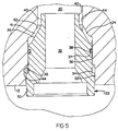
- Fig. 5 is an enlarged cross-sectional view of the aspirating member according to Fig. 2.
- Fig. 6 is a view of the gerotor pump showing a pinion gear and a ring gear positioned within a housing.
- Fig. 7 is a view of a planar member showing an inlet port and a discharge port.
- Fig. 8 is a cross-sectional view of a second embodiment of the aspirating member.
- Fig. 9 is a cross-sectional view of the second embodiment of the aspirating member along the line 9-9 in Fig. 8.
- Pump assembly 10 preferably for use in supplying fluid to a wet clutch and more preferably for use with a wet clutch of a motor vehicle.
- Pump assembly 10 generally includes a manifold 12 and a gerotor pump 14.
- Manifold 12 is placed in communication with a fluid reservoir (not illustrated) and is designed to route the flow of a fluid from the reservoir, through pump 14 and into a wet clutch (not illustrated).
- manifold 12 is preferably formed of a strong material, such as a steel or a high strength plastic, and generally includes a body 13 having a duct therethrough to allow passage of an input shaft (not illustrated) that transmits torque between a wet clutch and a transmission.
- Body 13 preferably includes a planar connecting structure 15 defining an inlet cavity 16 and an outlet cavity 18 therein.
- Manifold 12 further includes an intake port 20 that is preferably placed in direct communication with inlet cavity 16 and is designed to receive an aspirating member 22.
- a first duct 24 is preferably provided within body 13 that terminates on one end in intake port 20 and on the other end at an orifice 26.
- First duct 24 is preferably laterally offset to one side of a geometric center of aspirating member 22 to promote a vortex-like action in a fluid as the fluid flows from first duct 24 into intake port 20.
- a second duct 28 is preferably provided within body 13 that terminates on one end into first duct 24 and on the other end at an orifice (not illustrated).
- a flow control valve (not illustrated) is provided in the orifice to redirect a portion of the total fluid output of pump 14 in order to maintain the useful fluid output of pump 14 within a predetermined range. Fluid that is redirected by the flow control valve will flow through second duct 28 and first duct 24 into intake port 20.
- aspirating member 22 includes a generally cylindrical body 30 defining a duct 32 therethrough to allow passage of a fluid.
- Body 30 includes a first outer surface 33 preferably having a first annular cavity 34 disposed therein to receive a locking member 35, such as a rigid pin.
- a second outer surface 36 is provided having a diameter that is preferably smaller than first outer surface 33 and preferably includes a second annular cavity 37 disposed therein for receiving a sealing member 38, such as an o-ring.
- a radially contracting conical surface 39 extends from second outer surface 36 to a third outer surface 40 having a diameter that is preferably smaller than second outer surface 36.
- sealing member 38 in second annular cavity 37 sealingly engages a corresponding wall in intake port 20.
- a first annular void 41 is created between conical surface 39 and a corresponding conical surface 42 in intake port 20.
- a second annular void 43 is created between third outer surface 40 and a corresponding surface 44 in intake port 20.
- Voids 41 and 43 permit the free flow of fluid between aspirating member 22 and intake port 20 as the fluid enters intake 20 through first duct 24. Referring to Figs. 2 and 5, aspirating member 22 is preferably secured in intake port 20 by inserting locking member 35 into the area formed between cavities 34 and 44.
- An inlet tube 50 is secured to manifold 12 proximate aspirating member 22 to provide communication between aspirating member 22 and a remote fluid reservoir.
- Inlet tube 50 is preferably attached to manifold 12 via a plurality of threaded fasteners (not illustrated). However, it is recognized that other methods of attachment known in the art, such as welding, may be utilized to secure inlet tube 50 to manifold 12.
- pump 14 generally includes a housing 52 sandwiched between a flat inboard side 54 of a planar member 56 and a flat outboard side 58 of a cover 60. Relative rotation between housing 52, planar member 56 and cover 60 is prevented by a plurality of dowels 62 that are inserted through a plurality of commonly positioned apertures 63 in housing 52, planar member 56 and cover 60. A plurality of fasteners 64 positioned through cover 60, housing 52 and planar member 56 secure pump 14 to manifold 12.
- Pump 14 further includes a ring gear 66 having a cylindrical outside surface 68 that cooperates with a cylindrical inside surface 70 of housing 52 in supporting ring gear 66 for rotation about a first longitudinal centerline 72 parallel to and laterally separated from a second longitudinal centerline 73 of pump 14, as shown in Fig. 6.
- a pinion gear 74 of pump 14 is disposed inside of ring gear 66 and coupled to an input device (not illustrated) for rotation as a unit with the input device about second longitudinal centerline 73.
- the lateral separation between the first and second longitudinal centerlines 72, 73 defines a crescent-shaped cavity 80 between ring gear 66 and pinion gear 74.
- Cavity 80 is closed on opposite sides by flat inboard side 54 of planar member 56 and flat outboard side 58 of cover 60, respectively.
- the wedge-shaped ends of the crescent shaped cavity 80 are separated from each other by a tooth 82 on pinion gear 74 in full mesh with a pair of teeth 83A, 83B on ring gear 66.
- tooth 84 on pinion gear 74 cooperates with a tooth 85 on ring gear 66 in dividing the crescent-shaped cavity 80 into an inlet half 86 and a discharge half 88.
- the gear teeth on pinion gear 74 and ring gear 66 cooperate in defining a plurality of pump chambers 90 that expand in inlet half 86 of crescent-shaped cavity 80 and collapse in discharge half 88 of crescent-shaped cavity 80.
- an inlet port 92 in planar member 56 is disposed therethrough and faces inlet half 86 of crescent-shaped cavity 80.
- inlet port 92 is designed to communicate with the aforesaid fluid reservoir through inlet cavity 16 of manifold 12.
- inlet port 92 is preferably crescent-shaped and more preferably includes a relatively narrow upstream end 96 that expands into a relatively wider downstream end 98.
- the expanding width of inlet port 92 is preferably sized to match the similarly expanding width of inlet half 86 of crescent-shaped cavity 80.
- a discharge port 94 in planar member 56 is disposed therethrough and faces discharge half 88 of crescent-shaped cavity 80.
- Discharge port 94 is preferably crescent-shaped and more preferably includes a relatively wide upstream end 96' that contracts into a more narrow downstream end 98'. Like inlet port 92, the narrowing width of discharge port 94 is preferably sized to match the similarly narrowing width of discharge half 88 of crescent-shaped cavity 80. Matching the width of inlet port 92 and discharge port 94 to the width of inlet half 86 and discharge half 88, respectively, maximizes the fill efficiency of pump 14. Discharge port 94 communicates with the aforesaid clutch through outlet cavity 18 in manifold 12. The timing between inlet port 92 and a top-dead-center 99 of pump 14 is characterized by an angle theta 1 .
- the timing between top-dead-center 99 of pump 14 and discharge port 94 is characterized by an angle theta 2 .
- theta 1 is in the range of approximately 0° to 17° and more preferably approximately 7°.
- Theta 2 is preferably in the range of approximately 0° to 37° and more preferably approximately 37°.
- cover 60 preferably includes an inlet groove 100 characterized by geometry substantially similar to inlet port 92.
- Inlet groove 100 faces and therefore "shadows" inlet port 92 on the opposite side of crescent-shaped cavity 80 from inlet port 92.
- a discharge groove 102 characterized by geometry substantially similar to discharge port 94 is preferably disposed in cover 60 facing discharge port 94 on the opposite side of crescent-shaped cavity 80 from discharge port 94. Grooves 100, 102 balance the pressure within crescent-shaped cavity 80 to reduce friction and prevent premature wear of the components.
- a second embodiment of an aspirating member 22' having a generally cylindrical body 30' that includes a duct 32' therethrough to allow passage of a fluid from a fluid reservoir to inlet cavity 16 in manifold 12.
- Aspirating member 22' generally includes a first outer surface 33' preferably having a first annular cavity 34' disposed therein to receive a locking member 35'.
- Locking member 35' is preferably substantially similar in form and function to locking member 35 in the preferred embodiment of aspirating member 22.
- a second outer surface 36' is provided having a diameter that is preferably smaller than first outer surface 33' and more preferably includes a second annular cavity 37' for receiving a sealing member 38', such as an o-ring.
- An annular groove 104 extends from second outer surface 36' to a third outer surface 40' having a diameter that is preferably substantially similar to the diameter of second outer surface 36'.
- Third outer surface 40' preferably includes a third annular cavity 106 designed to receive a sealing member 38'.
- sealing members 38' in cavities 37' and 106 sealingly engage a corresponding wall 108 in intake port 20'.
- an annular void 41' is created between groove 104 and wall 108 in intake port 20'. Void 41' permits the free flow of fluid between aspirating member 22' and intake port 20' as the fluid enters intake port 20' through first duct 24.
- ducts 110 may be slightly angled when viewed axially to enhance the vortex-like action in the fluid.
- the operation of aspirating member 22' is substantially similar in operation to the preferred embodiment of aspirating member 22, as described in further detail below.
- first duct 24 creates a vortex in the fluid as it passes through voids 41 and 43 to further amplify the pressure drop.
- the high velocity fluid mixes with the relatively lower velocity inlet fluid, thereby transferring the momentum of the high velocity fluid to the inlet fluid.
- the mix of fluid then enters inlet cavity 16 at a mean velocity that, when slowed in inlet cavity 16, results in an increase in the static pressure at the pump inlet.
- Operation of aspirating member 22 transfers fluid from the reservoir to inlet cavity 16 of pump 14 at a moderate charging pressure to suppress cavitation at the expanding pump chambers 90 of pump 14 in the inlet half 86 of the crescent-shaped cavity 80.
- Inlet half 86 of crescent-shaped cavity 80 expands as it passes inlet cavity 16 and the corresponding inlet port 92 in planar member 56.
- the expanding pumping chambers 90 draw in the "supercharged” inlet flow as pumping chambers 90 traverse crescent-shaped cavity 80.
- the extended timing of inlet port 92 and "supercharged” inlet flow cooperate to permit pumping chambers 90 to completely fill with fluid.
- the extended timing and "supercharged” inlet flow alone operate to improve the volumetric efficiency of pump 14, even when no cavitation is present.
Landscapes
- Engineering & Computer Science (AREA)
- Chemical & Material Sciences (AREA)
- Combustion & Propulsion (AREA)
- Mechanical Engineering (AREA)
- General Engineering & Computer Science (AREA)
- Rotary Pumps (AREA)
- Details And Applications Of Rotary Liquid Pumps (AREA)
Abstract
Description
- The present invention relates generally to a positive displacement fluid pump and more specifically to a gerotor pump assembly suitable for use in hydraulic systems.
- In a positive displacement fluid pump commonly referred to as a gerotor pump, a ring gear and a pinion gear inside of the ring gear are supported in a pump housing for rotation about parallel, laterally separated centerlines. The teeth on the respective gears cooperate to define a plurality of variable volume pumping chambers whereupon during rotation of the gear members, a pumping chamber increases in volume to a maximum volume and then decreases in volume. Fluid from the relatively low pressure inlet port of the pump is drawn into pumping chambers that are increasing in volume. Upon further rotation of the gerotor when the pumping chambers are decreasing in volume, the fluid is pushed out through the outlet port of the pump at a relatively higher pressure. The inlet and the outlet ports are separated angularly or "timed" to prevent the pump chambers from simultaneously overlapping both the inlet port and the outlet port.
- A common limitation exhibited by many gerotor pumps is excessive noise caused by cavitation (the rapid formation and collapse of bubbles in the pumped fluid). Cavitation in gerotor pumps is generally caused by the pump speed being greater than the time required to fill the pumping chambers. The incomplete charge of the pumping chambers entraps air or other vapor within the fluid. If not accounted for, the entrapped vapor bubbles collapse in the discharge port creating noise inducing pressure pulses that also decrease pump efficiency. The present invention provides a pump assembly with improved charging and timing conditions to reduce cavitation and resulting noise.
- The present invention provides a new and improved positive displacement pump assembly with improved timing, porting geometry and inlet fluid mechanics to improve fill and reduce cavitation.
- In accordance with an embodiment of the present invention, a pump assembly is provided that includes a gerotor pump and a manifold. An aspirating member is positioned between an inlet cavity in the manifold and a fluid reservoir proximate the pump assembly. High pressure fluid diverted by a flow control valve accelerates as it passes between the aspirating member and the manifold. The resulting lower static pressure draws the fluid out of the reservoir where it mixes with the relatively higher velocity diverted fluid. As the combined fluid is slowed, the static pressure increases to "supercharge" the inlet cavity resulting in an improvement in the inlet fill and a reduction in cavitation.
- In accordance with another embodiment of this invention, a gerotor pump is provided with a plurality of pump chambers defined by the teeth of a ring gear and a pinion gear. The pumping chambers expand in an inlet half of a crescent-shaped cavity created between the ring gear and the pinion gear and collapse in a discharge half of the crescent-shaped cavity. An inlet port in a planar member faces the inlet half of the crescent-shaped cavity. A discharge port in the planar member faces the discharge half of the crescent-shaped cavity and is timed relative to the inlet port for pumping the fluid. The timing and geometry of the input port and output port are optimized to prevent noise inducing pressure spikes while maintaining sufficient back pressure in the pump chambers to collapse entrapped vapor bubbles in the fluid.
- Various additional aspects and advantages of this invention will become apparent to those skilled in the art from the following detailed description of the preferred embodiment, when read in light of the accompanying drawings.
- The features and inventive aspects of the present invention will become more apparent upon reading the following detailed description, claims, and drawings, of which the following is a brief description:
- Fig. 1 is an exploded perspective view of an embodiment of the present invention showing a manifold and gerotor pump.
- Fig. 2 is a partial sectional view of the manifold according to Fig. 1 showing an aspirating member according to a preferred embodiment.
- Fig. 3 is a cross-sectional view of the manifold and aspirating member along the line 3-3 in Fig. 2.
- Fig. 4 is a cross-sectional view of the manifold and aspirating member along the line 4-4 in Fig. 3.
- Fig. 5 is an enlarged cross-sectional view of the aspirating member according to Fig. 2.
- Fig. 6 is a view of the gerotor pump showing a pinion gear and a ring gear positioned within a housing.
- Fig. 7 is a view of a planar member showing an inlet port and a discharge port.
- Fig. 8 is a cross-sectional view of a second embodiment of the aspirating member.
- Fig. 9 is a cross-sectional view of the second embodiment of the aspirating member along the line 9-9 in Fig. 8.
- Referring now to the drawings, two preferred embodiments of the present invention are described in detail. Referring to Fig. 1, a preferred embodiment of the present invention is shown that includes a pump assembly 10, preferably for use in supplying fluid to a wet clutch and more preferably for use with a wet clutch of a motor vehicle. Pump assembly 10 generally includes a
manifold 12 and agerotor pump 14. Manifold 12 is placed in communication with a fluid reservoir (not illustrated) and is designed to route the flow of a fluid from the reservoir, throughpump 14 and into a wet clutch (not illustrated). - Referring to Figs. 1, 2 and 3,
manifold 12 is preferably formed of a strong material, such as a steel or a high strength plastic, and generally includes abody 13 having a duct therethrough to allow passage of an input shaft (not illustrated) that transmits torque between a wet clutch and a transmission.Body 13 preferably includes a planar connectingstructure 15 defining aninlet cavity 16 and anoutlet cavity 18 therein. Manifold 12 further includes anintake port 20 that is preferably placed in direct communication withinlet cavity 16 and is designed to receive an aspiratingmember 22. As shown in Figs. 3 and 4, afirst duct 24 is preferably provided withinbody 13 that terminates on one end inintake port 20 and on the other end at anorifice 26.First duct 24 is preferably laterally offset to one side of a geometric center of aspiratingmember 22 to promote a vortex-like action in a fluid as the fluid flows fromfirst duct 24 intointake port 20. Asecond duct 28 is preferably provided withinbody 13 that terminates on one end intofirst duct 24 and on the other end at an orifice (not illustrated). A flow control valve (not illustrated) is provided in the orifice to redirect a portion of the total fluid output ofpump 14 in order to maintain the useful fluid output ofpump 14 within a predetermined range. Fluid that is redirected by the flow control valve will flow throughsecond duct 28 andfirst duct 24 intointake port 20. - Referring to Fig. 5, in a preferred embodiment, aspirating
member 22 includes a generallycylindrical body 30 defining aduct 32 therethrough to allow passage of a fluid.Body 30 includes a firstouter surface 33 preferably having a firstannular cavity 34 disposed therein to receive alocking member 35, such as a rigid pin. A secondouter surface 36 is provided having a diameter that is preferably smaller than firstouter surface 33 and preferably includes a secondannular cavity 37 disposed therein for receiving asealing member 38, such as an o-ring. A radially contractingconical surface 39 extends from secondouter surface 36 to a thirdouter surface 40 having a diameter that is preferably smaller than secondouter surface 36. When aspiratingmember 22 is received inintake port 20, sealingmember 38 in secondannular cavity 37 sealingly engages a corresponding wall inintake port 20. Additionally, a firstannular void 41 is created betweenconical surface 39 and a correspondingconical surface 42 inintake port 20. Similarly, a secondannular void 43 is created between thirdouter surface 40 and acorresponding surface 44 inintake port 20.Voids member 22 andintake port 20 as the fluid enters intake 20 throughfirst duct 24. Referring to Figs. 2 and 5, aspiratingmember 22 is preferably secured inintake port 20 by insertinglocking member 35 into the area formed betweencavities inlet tube 50 is secured to manifold 12 proximate aspiratingmember 22 to provide communication between aspiratingmember 22 and a remote fluid reservoir.Inlet tube 50 is preferably attached tomanifold 12 via a plurality of threaded fasteners (not illustrated). However, it is recognized that other methods of attachment known in the art, such as welding, may be utilized to secureinlet tube 50 to manifold 12. - Referring to Figs. 1 and 6,
pump 14 generally includes ahousing 52 sandwiched between a flatinboard side 54 of aplanar member 56 and aflat outboard side 58 of acover 60. Relative rotation betweenhousing 52,planar member 56 andcover 60 is prevented by a plurality ofdowels 62 that are inserted through a plurality of commonly positionedapertures 63 inhousing 52,planar member 56 andcover 60. A plurality offasteners 64 positioned throughcover 60,housing 52 andplanar member 56secure pump 14 to manifold 12.Pump 14 further includes aring gear 66 having a cylindricaloutside surface 68 that cooperates with a cylindricalinside surface 70 ofhousing 52 in supportingring gear 66 for rotation about a firstlongitudinal centerline 72 parallel to and laterally separated from a secondlongitudinal centerline 73 ofpump 14, as shown in Fig. 6. Apinion gear 74 ofpump 14 is disposed inside ofring gear 66 and coupled to an input device (not illustrated) for rotation as a unit with the input device about secondlongitudinal centerline 73. - Referring to Fig. 6, the lateral separation between the first and second
longitudinal centerlines cavity 80 betweenring gear 66 andpinion gear 74.Cavity 80 is closed on opposite sides by flatinboard side 54 ofplanar member 56 and flatoutboard side 58 ofcover 60, respectively. The wedge-shaped ends of the crescent shapedcavity 80 are separated from each other by atooth 82 onpinion gear 74 in full mesh with a pair ofteeth ring gear 66. With counterclockwise rotation ofring gear 66 andpinion gear 74 as indicated by the directional arrows in Fig. 6,tooth 84 onpinion gear 74 cooperates with atooth 85 onring gear 66 in dividing the crescent-shapedcavity 80 into aninlet half 86 and adischarge half 88. The gear teeth onpinion gear 74 andring gear 66 cooperate in defining a plurality ofpump chambers 90 that expand ininlet half 86 of crescent-shapedcavity 80 and collapse indischarge half 88 of crescent-shapedcavity 80. - Referring to Fig. 7, an
inlet port 92 inplanar member 56 is disposed therethrough and facesinlet half 86 of crescent-shapedcavity 80. Upon assembly ofpump 14,inlet port 92 is designed to communicate with the aforesaid fluid reservoir throughinlet cavity 16 ofmanifold 12. Like crescent-shapedcavity 80,inlet port 92 is preferably crescent-shaped and more preferably includes a relatively narrowupstream end 96 that expands into a relatively widerdownstream end 98. The expanding width ofinlet port 92 is preferably sized to match the similarly expanding width ofinlet half 86 of crescent-shapedcavity 80. Adischarge port 94 inplanar member 56 is disposed therethrough and facesdischarge half 88 of crescent-shapedcavity 80.Discharge port 94 is preferably crescent-shaped and more preferably includes a relatively wide upstream end 96' that contracts into a more narrow downstream end 98'. Likeinlet port 92, the narrowing width ofdischarge port 94 is preferably sized to match the similarly narrowing width ofdischarge half 88 of crescent-shapedcavity 80. Matching the width ofinlet port 92 anddischarge port 94 to the width ofinlet half 86 anddischarge half 88, respectively, maximizes the fill efficiency ofpump 14.Discharge port 94 communicates with the aforesaid clutch throughoutlet cavity 18 inmanifold 12. The timing betweeninlet port 92 and a top-dead-center 99 ofpump 14 is characterized by an angle theta1. The timing between top-dead-center 99 ofpump 14 anddischarge port 94 is characterized by an angle theta2. In a preferred embodiment, theta1 is in the range of approximately 0° to 17° and more preferably approximately 7°. Theta2 is preferably in the range of approximately 0° to 37° and more preferably approximately 37°. In this configuration, thetime inlet half 86 of crescent-shapedcavity 80 spends in communication withinlet port 92 is maximized such thatinlet half 86 completely fills with fluid to prevent cavitation within pumpingchambers 90. - Referring to Fig. 1, cover 60 preferably includes an
inlet groove 100 characterized by geometry substantially similar toinlet port 92.Inlet groove 100 faces and therefore "shadows"inlet port 92 on the opposite side of crescent-shapedcavity 80 frominlet port 92. Similarly, adischarge groove 102 characterized by geometry substantially similar to dischargeport 94 is preferably disposed incover 60 facingdischarge port 94 on the opposite side of crescent-shapedcavity 80 fromdischarge port 94.Grooves cavity 80 to reduce friction and prevent premature wear of the components. - Referring to Fig. 8, a second embodiment of an aspirating member 22' is provided having a generally cylindrical body 30' that includes a duct 32' therethrough to allow passage of a fluid from a fluid reservoir to
inlet cavity 16 inmanifold 12. Aspirating member 22' generally includes a first outer surface 33' preferably having a first annular cavity 34' disposed therein to receive a locking member 35'. Locking member 35' is preferably substantially similar in form and function to lockingmember 35 in the preferred embodiment of aspiratingmember 22. A second outer surface 36' is provided having a diameter that is preferably smaller than first outer surface 33' and more preferably includes a second annular cavity 37' for receiving a sealingmember 38', such as an o-ring. An annular groove 104 extends from second outer surface 36' to a third outer surface 40' having a diameter that is preferably substantially similar to the diameter of second outer surface 36'. Third outer surface 40' preferably includes a thirdannular cavity 106 designed to receive a sealingmember 38'. When aspirating member 22' is received in an intake port 20', sealingmembers 38' incavities 37' and 106 sealingly engage acorresponding wall 108 in intake port 20'. Additionally, an annular void 41' is created between groove 104 andwall 108 in intake port 20'. Void 41' permits the free flow of fluid between aspirating member 22' and intake port 20' as the fluid enters intake port 20' throughfirst duct 24. The fluid entering fromfirst duct 24 is accelerated through a plurality ofducts 110 exiting at a relatively high velocity. Additionally, as shown in Fig. 9,ducts 110 may be slightly angled when viewed axially to enhance the vortex-like action in the fluid. The operation of aspirating member 22' is substantially similar in operation to the preferred embodiment of aspiratingmember 22, as described in further detail below. - Operation of the inventive pump assembly 10 will be described with reference to Figs. 1, 3, 4, 5 and 6. Rotation of the input device (not illustrated) causes the
pinion gear 74 andring gear 66 to rotate. High pressure fluid diverted by the flow control valve (not illustrated) travels throughsecond duct 28 andfirst duct 24 until it encounters aspiratingmember 22. The high pressure fluid is accelerated throughvoids member 22. The low static pressure at the outlet of aspiratingmember 22 works as a suction to draw in fluid from the reservoir throughduct 32. Additionally, the offset offirst duct 24 creates a vortex in the fluid as it passes throughvoids inlet cavity 16 at a mean velocity that, when slowed ininlet cavity 16, results in an increase in the static pressure at the pump inlet. Operation of aspiratingmember 22 transfers fluid from the reservoir toinlet cavity 16 ofpump 14 at a moderate charging pressure to suppress cavitation at the expandingpump chambers 90 ofpump 14 in theinlet half 86 of the crescent-shapedcavity 80. -
Inlet half 86 of crescent-shapedcavity 80 expands as it passesinlet cavity 16 and thecorresponding inlet port 92 inplanar member 56. The expandingpumping chambers 90 draw in the "supercharged" inlet flow as pumpingchambers 90 traverse crescent-shapedcavity 80. The extended timing ofinlet port 92 and "supercharged" inlet flow cooperate to permit pumpingchambers 90 to completely fill with fluid. The extended timing and "supercharged" inlet flow alone operate to improve the volumetric efficiency ofpump 14, even when no cavitation is present. Moreover, by removing upstream end 96' ofoutlet port 94 an angle of theta2 from top-dead-center 99 ofpump 14, the entering fluid is pre-compressed to reduce cavitation and resulting noise. As each of pumpingchambers 90 traverses crescent-shapedcavity 80 frominlet half 86 to dischargehalf 88, the fluid in pumpingchambers 90 is momentarily completely trapped to assure separation betweeninlet cavity 16 andoutlet cavity 18. The fluid is expelled from the collapsingpump chambers 90 indischarge half 88 of crescent-shapedcavity 80 throughdischarge port 94 and intooutlet cavity 18. - Although certain preferred embodiments of the present invention have been described, the invention is not limited to the illustrations described and shown herein, which are deemed to be merely illustrative of the best modes of carrying out the invention. A person of ordinary skill in the art will realize that certain modifications and variations will come within the teachings of this invention and that such variations and modifications are within its spirit and the scope as defined by the claims.
Claims (20)
- A positive displacement fluid pump assembly comprising:a pumping unit;a manifold for directing fluid flow to and from said pumping unit;an aspirating member positioned between a pump inlet cavity in said manifold and a fluid reservoir, said aspirating member having a duct therethrough to permit passage of a fluid from said reservoir into said inlet cavity.
- A pump according to claim 1, wherein said aspirating member is received in said manifold.
- A pump according to claim 2, wherein said aspirating member and said manifold define at least one void therebetween to permit passage of a portion of said fluid flow generated by said pumping unit into said inlet cavity.
- A pump according to claim 2, wherein said aspirating member further includes at least one annular cavity having a sealing member disposed therein.
- A pump according to claim 2, wherein said manifold further includes a duct to supply said portion of said fluid flow generated by said pumping unit to said aspirating member.
- A pump according to claim 5, wherein said duct is laterally offset to one side of a geometric center of said aspirating member.
- A pump according to claim 1, wherein said pumping unit includes a planar member having an outlet port and an inlet port disposed therethrough.
- A pump according to claim 7, wherein said inlet port and outlet port in said planar member correspond to said inlet cavity and an outlet cavity in said manifold.
- A pump according to claim 7, wherein said inlet port is generally crescent shaped having a downstream end removed an angle theta1 from a top-dead-center of said pumping unit.
- A pump according to claim 9, wherein said angle theta1 is in a range of approximately 0° to 17°.
- A pump according to claim 10, wherein said angle theta1 is approximately 7°.
- A pump according to claim 7, wherein said outlet port is generally crescent shaped having an upstream end removed an angle theta2 from a top-dead-center of said pumping unit.
- A pump according to claim 12, wherein said angle theta2 is in a range of approximately 0° to 37°.
- A pump according to claim 13, wherein said angle theta2 is approximately 37°.
- A positive displacement fluid pump comprising:an outer ring gear rotatable in a housing of said pump about a first centerline;an inner pinion gear inside of said ring gear rotatable on said housing of said pump about a second centerline parallel to and separated from said first centerline so that a crescent-shaped cavity is defined between said ring gear and said pinion gear;a pair of planar sides of said housing enclosing opposite sides of said crescent-shaped cavity;a plurality of gear teeth on said ring gear and on said pinion gear cooperating in dividing said crescent-shaped cavity into an inlet half and a discharge half and into a plurality of pump chambers traversing said crescent-shaped cavity from said inlet half to said discharge half;an inlet port in a first one of said pair of planar sides of said housing facing said inlet half of said crescent-shaped cavity, said inlet port having a downstream end that is separated angularly from a top-dead-center of said pump by a timing angle theta1; anda discharge port in said first one of said pair of planar sides of said housing facing said discharge half of said crescent-shaped cavity, said outlet port having an upstream end that is separated angularly from said top-dead-center by a timing angle theta2.
- A pump according to claim 15, wherein said angle theta1 is in a range of approximately 0° to 17°.
- A pump according to claim 16, wherein said angle theta1 is approximately 7°.
- A pump according to claim 15, wherein said angle theta2 is in a range of approximately 0° to 37°.
- A pump according to claim 18, wherein said angle theta2 is approximately 37°.
- A positive displacement fluid pump assembly for use in supplying a fluid to operate a wet clutch assembly, said pump assembly comprising:wherein said aspirating member and said manifold define at least one void therebetween to permit passage of a portion of said fluid flow generated by said gerotor pump into said inlet cavity.a gerotor pump having an outer ring gear rotatable in a housing of said pump about a first centerline, an inner pinion gear inside of said ring gear rotatable on said housing of said pump about a second centerline parallel to and separated from said first centerline so that a crescent-shaped cavity is defined between said ring gear and said pinion gear, a pair of planar sides of said housing closing opposite sides of said crescent-shaped cavity, a plurality of gear teeth on said ring gear and on said pinion gear cooperating in dividing said crescent-shaped cavity into an inlet half and a discharge half and into a plurality of pump chambers traversing said crescent-shaped cavity from said inlet half to said discharge half, an inlet port in a first one of said pair of planar sides of said housing facing said inlet half of said crescent-shaped cavity, said inlet port having a downstream end that is separated angularly from a top-dead-center of said pump by a timing angle theta1 that exceeds zero degrees, and a discharge port in said first one of said pair of planar sides of said housing facing said discharge half of said crescent-shaped cavity, said outlet port having an upstream end that is separated angularly from said top-dead-center by a timing angle theta2 that exceeds zero degrees;a manifold secured to said gerotor pump for directing fluid flow to and from said gerotor pump, said manifold including a port designed to receive an aspirating member, said aspirating member having a duct therethrough to permit passage of a fluid from a reservoir into an pump inlet cavity in said manifold; and
Applications Claiming Priority (2)
| Application Number | Priority Date | Filing Date | Title |
|---|---|---|---|
| US822059 | 2001-03-30 | ||
| US09/822,059 US6572339B2 (en) | 2001-03-30 | 2001-03-30 | Positive displacement fluid pump having improved fill characteristics |
Publications (2)
| Publication Number | Publication Date |
|---|---|
| EP1245831A2 true EP1245831A2 (en) | 2002-10-02 |
| EP1245831A3 EP1245831A3 (en) | 2002-12-04 |
Family
ID=25235008
Family Applications (1)
| Application Number | Title | Priority Date | Filing Date |
|---|---|---|---|
| EP02006215A Withdrawn EP1245831A3 (en) | 2001-03-30 | 2002-03-20 | Pump assembly |
Country Status (2)
| Country | Link |
|---|---|
| US (1) | US6572339B2 (en) |
| EP (1) | EP1245831A3 (en) |
Cited By (1)
| Publication number | Priority date | Publication date | Assignee | Title |
|---|---|---|---|---|
| US9719232B2 (en) | 2011-12-22 | 2017-08-01 | Ihc Engineering Business Limited | Pump apparatus and underwater trenching apparatus |
Families Citing this family (5)
| Publication number | Priority date | Publication date | Assignee | Title |
|---|---|---|---|---|
| US7168247B1 (en) | 2003-07-24 | 2007-01-30 | Hydro-Gear Limited Partnership | Charge pump |
| US7192257B2 (en) * | 2003-09-12 | 2007-03-20 | Ford Global Technologies, Llc | Jet pump for boosting pressure at an inlet supplied from a sump and second fluid source |
| US20070201989A1 (en) * | 2005-10-14 | 2007-08-30 | Parker-Hannifin | Low ripple gear pump/motor |
| US20080273992A1 (en) * | 2007-05-03 | 2008-11-06 | Metaldyne Company Llc. | Cavitation-deterring energy-efficient fluid pump system and method of operation |
| CA2967606C (en) | 2017-05-18 | 2023-05-09 | Peter Neufeld | Seal housing and related apparatuses and methods of use |
Citations (2)
| Publication number | Priority date | Publication date | Assignee | Title |
|---|---|---|---|---|
| US3348491A (en) | 1966-03-07 | 1967-10-24 | Borg Warner | Hydraulic pump and sump |
| US5395217A (en) | 1991-06-07 | 1995-03-07 | Schwabische Huttenwerke Gmbh | Gear pump for oil for an internal-combustion engine, in particular for motor vehicles |
Family Cites Families (18)
| Publication number | Priority date | Publication date | Assignee | Title |
|---|---|---|---|---|
| US3166018A (en) | 1963-11-08 | 1965-01-19 | Jr Cresswell E Stedman | Fluid pump body and gear set |
| US3563674A (en) * | 1968-07-16 | 1971-02-16 | Gen Signal Corp | Aspirating device |
| GB1353010A (en) * | 1970-08-25 | 1974-05-15 | Plessey Co Ltd | Systems for the supply of liquid to a consumer more particularly of liquid fuel to gasturbine engines |
| US3922113A (en) * | 1972-01-06 | 1975-11-25 | Plessey Co Ltd | Metered supply of liquids |
| NL7406050A (en) | 1973-05-08 | 1974-11-12 | ||
| US4488852A (en) * | 1976-11-26 | 1984-12-18 | Engineers Sales-Service Co., Inc. | Submersible pump apparatus |
| US4183425A (en) | 1977-08-11 | 1980-01-15 | G. M. Sommer Company, Inc. | Clutch-brake with speed differential coolant pump |
| US4420292A (en) | 1981-03-09 | 1983-12-13 | Borg-Warner Corporation | Bi-directional internal/external gear pump with advanced porting |
| GB2110759A (en) | 1981-11-27 | 1983-06-22 | Concentric Pumps Ltd | Rotary positive-displacement fluid-machines |
| US4408961A (en) * | 1982-02-16 | 1983-10-11 | Chandler Evans, Inc. | Jet pump with integral pressure regulator |
| GB2150981A (en) | 1983-11-10 | 1985-07-10 | Vs Eng Ltd | Apparatus and method for pumping a fluid |
| US5544540A (en) | 1994-12-29 | 1996-08-13 | Dana Corporation | Gerotor pump for vehicle transmission lubrication system |
| HU219961B (en) | 1995-09-14 | 2001-10-28 | Edward Grenke | Wellhead drive brake, pump system and method for actuating it |
| JP3530664B2 (en) | 1996-01-25 | 2004-05-24 | 富士重工業株式会社 | Internal gear type fluid device |
| KR100528952B1 (en) * | 1997-09-04 | 2005-11-16 | 스미또모 덴꼬 쇼오께쯔 고오낑 가부시끼가이샤 | Internal gear pump |
| US6106240A (en) * | 1998-04-27 | 2000-08-22 | General Motors Corporation | Gerotor pump |
| US6113360A (en) * | 1998-07-27 | 2000-09-05 | Ford Motor Company | Gerotor pump |
| DE19942567A1 (en) | 1999-09-07 | 2001-03-22 | Fluidtech Gmbh | Fluid pumping device |
-
2001
- 2001-03-30 US US09/822,059 patent/US6572339B2/en not_active Expired - Lifetime
-
2002
- 2002-03-20 EP EP02006215A patent/EP1245831A3/en not_active Withdrawn
Patent Citations (2)
| Publication number | Priority date | Publication date | Assignee | Title |
|---|---|---|---|---|
| US3348491A (en) | 1966-03-07 | 1967-10-24 | Borg Warner | Hydraulic pump and sump |
| US5395217A (en) | 1991-06-07 | 1995-03-07 | Schwabische Huttenwerke Gmbh | Gear pump for oil for an internal-combustion engine, in particular for motor vehicles |
Cited By (1)
| Publication number | Priority date | Publication date | Assignee | Title |
|---|---|---|---|---|
| US9719232B2 (en) | 2011-12-22 | 2017-08-01 | Ihc Engineering Business Limited | Pump apparatus and underwater trenching apparatus |
Also Published As
| Publication number | Publication date |
|---|---|
| US6572339B2 (en) | 2003-06-03 |
| US20020141878A1 (en) | 2002-10-03 |
| EP1245831A3 (en) | 2002-12-04 |
Similar Documents
| Publication | Publication Date | Title |
|---|---|---|
| EP0785361B1 (en) | Oil pump apparatus | |
| KR20210108396A (en) | Pump assembly with two pumps provided in a single housing | |
| JPS62121885A (en) | Rotating volume type blower and method of improving air transmission noise and volume efficiency by using said device | |
| JP6381871B2 (en) | Fluid pump | |
| US6332522B1 (en) | Hydraulic coupling for vehicle drivetrain | |
| US6572339B2 (en) | Positive displacement fluid pump having improved fill characteristics | |
| JPH05263770A (en) | Oil pump | |
| US6527505B2 (en) | Regenerative fuel pump flow chamber | |
| US3614266A (en) | Compact positive displacement pump | |
| US6287094B1 (en) | Inlet tube diffuser element for a hydraulic pump | |
| US4355964A (en) | Gear pump having fluid deaeration capability | |
| US4347047A (en) | Hydraulic pump for power steering | |
| JPH08210210A (en) | Fuel delivery pump for fuel injection pump of internal combustion engine | |
| EP4326990A1 (en) | Submersible pump | |
| US4347048A (en) | Hydraulic pump for power steering | |
| US5685704A (en) | Rotary gear pump having asymmetrical convex tooth profiles | |
| JP2785386B2 (en) | Mission oil passage | |
| KR20190018359A (en) | Triangular rotary pump equipped with pulsation reducing means | |
| JPH06213093A (en) | Conveyor of fuel from storage tank to internal combustion engine of automobile | |
| KR100381801B1 (en) | Rotary displacement pump | |
| EP1357290A2 (en) | Pump apparatus with bypass flow control valve | |
| JPH0613869B2 (en) | Dual vane pump | |
| US11795945B2 (en) | Pump device with air introduction hole that opens into pump chamber at predetermined opening time immediately before suction stroke | |
| US7168247B1 (en) | Charge pump | |
| JP3853939B2 (en) | Trochoid pump |
Legal Events
| Date | Code | Title | Description |
|---|---|---|---|
| PUAI | Public reference made under article 153(3) epc to a published international application that has entered the european phase |
Free format text: ORIGINAL CODE: 0009012 |
|
| AK | Designated contracting states |
Kind code of ref document: A2 Designated state(s): AT BE CH CY DE DK ES FI FR GB GR IE IT LI LU MC NL PT SE TR |
|
| AX | Request for extension of the european patent |
Free format text: AL;LT;LV;MK;RO;SI |
|
| PUAL | Search report despatched |
Free format text: ORIGINAL CODE: 0009013 |
|
| AK | Designated contracting states |
Kind code of ref document: A3 Designated state(s): AT BE CH CY DE DK ES FI FR GB GR IE IT LI LU MC NL PT SE TR |
|
| AX | Request for extension of the european patent |
Free format text: AL;LT;LV;MK;RO;SI |
|
| 17P | Request for examination filed |
Effective date: 20030130 |
|
| AKX | Designation fees paid |
Designated state(s): DE FR GB IT |
|
| 17Q | First examination report despatched |
Effective date: 20080818 |
|
| STAA | Information on the status of an ep patent application or granted ep patent |
Free format text: STATUS: THE APPLICATION IS DEEMED TO BE WITHDRAWN |
|
| 18D | Application deemed to be withdrawn |
Effective date: 20101001 |