EP1245698B1 - Coated cemented carbide cutting tool - Google Patents
Coated cemented carbide cutting tool Download PDFInfo
- Publication number
- EP1245698B1 EP1245698B1 EP02006607A EP02006607A EP1245698B1 EP 1245698 B1 EP1245698 B1 EP 1245698B1 EP 02006607 A EP02006607 A EP 02006607A EP 02006607 A EP02006607 A EP 02006607A EP 1245698 B1 EP1245698 B1 EP 1245698B1
- Authority
- EP
- European Patent Office
- Prior art keywords
- layer
- cutting
- hard coating
- cemented carbide
- thin layer
- Prior art date
- Legal status (The legal status is an assumption and is not a legal conclusion. Google has not performed a legal analysis and makes no representation as to the accuracy of the status listed.)
- Expired - Lifetime
Links
- 238000005520 cutting process Methods 0.000 title claims abstract description 158
- 239000010410 layer Substances 0.000 claims abstract description 190
- 239000011247 coating layer Substances 0.000 claims abstract description 80
- 239000000758 substrate Substances 0.000 claims abstract description 38
- 239000000463 material Substances 0.000 claims abstract description 19
- 150000003609 titanium compounds Chemical class 0.000 claims abstract description 8
- PNEYBMLMFCGWSK-UHFFFAOYSA-N aluminium oxide Inorganic materials [O-2].[O-2].[O-2].[Al+3].[Al+3] PNEYBMLMFCGWSK-UHFFFAOYSA-N 0.000 claims description 5
- 229910052593 corundum Inorganic materials 0.000 claims description 5
- 229910001845 yogo sapphire Inorganic materials 0.000 claims description 5
- ATJFFYVFTNAWJD-UHFFFAOYSA-N Tin Chemical compound [Sn] ATJFFYVFTNAWJD-UHFFFAOYSA-N 0.000 claims description 2
- CJNBYAVZURUTKZ-UHFFFAOYSA-N hafnium(IV) oxide Inorganic materials O=[Hf]=O CJNBYAVZURUTKZ-UHFFFAOYSA-N 0.000 claims description 2
- NRTOMJZYCJJWKI-UHFFFAOYSA-N Titanium nitride Chemical compound [Ti]#N NRTOMJZYCJJWKI-UHFFFAOYSA-N 0.000 description 35
- TWNQGVIAIRXVLR-UHFFFAOYSA-N oxo(oxoalumanyloxy)alumane Chemical compound O=[Al]O[Al]=O TWNQGVIAIRXVLR-UHFFFAOYSA-N 0.000 description 31
- 229910000831 Steel Inorganic materials 0.000 description 23
- 239000010959 steel Substances 0.000 description 23
- 238000000151 deposition Methods 0.000 description 22
- 230000008021 deposition Effects 0.000 description 22
- 229910001018 Cast iron Inorganic materials 0.000 description 18
- CSCPPACGZOOCGX-UHFFFAOYSA-N Acetone Chemical compound CC(C)=O CSCPPACGZOOCGX-UHFFFAOYSA-N 0.000 description 16
- 238000012360 testing method Methods 0.000 description 16
- 238000005299 abrasion Methods 0.000 description 14
- 239000002826 coolant Substances 0.000 description 14
- 229910000449 hafnium oxide Inorganic materials 0.000 description 13
- 229910003074 TiCl4 Inorganic materials 0.000 description 12
- VSCWAEJMTAWNJL-UHFFFAOYSA-K aluminium trichloride Chemical compound Cl[Al](Cl)Cl VSCWAEJMTAWNJL-UHFFFAOYSA-K 0.000 description 12
- 239000007789 gas Substances 0.000 description 12
- XJDNKRIXUMDJCW-UHFFFAOYSA-J titanium tetrachloride Chemical compound Cl[Ti](Cl)(Cl)Cl XJDNKRIXUMDJCW-UHFFFAOYSA-J 0.000 description 12
- 238000005229 chemical vapour deposition Methods 0.000 description 11
- 239000000843 powder Substances 0.000 description 11
- 239000000203 mixture Substances 0.000 description 9
- 238000004519 manufacturing process Methods 0.000 description 8
- 238000001035 drying Methods 0.000 description 7
- 238000011835 investigation Methods 0.000 description 7
- 230000003287 optical effect Effects 0.000 description 7
- 238000010926 purge Methods 0.000 description 7
- 239000010936 titanium Substances 0.000 description 7
- 238000005406 washing Methods 0.000 description 7
- 230000009466 transformation Effects 0.000 description 5
- WEVYAHXRMPXWCK-UHFFFAOYSA-N Acetonitrile Chemical compound CC#N WEVYAHXRMPXWCK-UHFFFAOYSA-N 0.000 description 4
- 230000008859 change Effects 0.000 description 4
- 230000001684 chronic effect Effects 0.000 description 4
- 150000001875 compounds Chemical class 0.000 description 4
- 239000000470 constituent Substances 0.000 description 4
- 239000013078 crystal Substances 0.000 description 4
- 229910052751 metal Inorganic materials 0.000 description 4
- 239000002184 metal Substances 0.000 description 4
- RTAQQCXQSZGOHL-UHFFFAOYSA-N Titanium Chemical compound [Ti] RTAQQCXQSZGOHL-UHFFFAOYSA-N 0.000 description 3
- 238000000034 method Methods 0.000 description 3
- 229910052594 sapphire Inorganic materials 0.000 description 3
- 229910001220 stainless steel Inorganic materials 0.000 description 3
- 239000010935 stainless steel Substances 0.000 description 3
- 229910052719 titanium Inorganic materials 0.000 description 3
- MCMNRKCIXSYSNV-UHFFFAOYSA-N Zirconium dioxide Chemical compound O=[Zr]=O MCMNRKCIXSYSNV-UHFFFAOYSA-N 0.000 description 2
- -1 acetonitrile (CH3CN) Chemical class 0.000 description 2
- 229910002091 carbon monoxide Inorganic materials 0.000 description 2
- 238000000576 coating method Methods 0.000 description 2
- 230000000694 effects Effects 0.000 description 2
- 230000002349 favourable effect Effects 0.000 description 2
- 230000020169 heat generation Effects 0.000 description 2
- 238000003801 milling Methods 0.000 description 2
- 230000008569 process Effects 0.000 description 2
- 229910003470 tongbaite Inorganic materials 0.000 description 2
- UONOETXJSWQNOL-UHFFFAOYSA-N tungsten carbide Chemical compound [W+]#[C-] UONOETXJSWQNOL-UHFFFAOYSA-N 0.000 description 2
- 229910003865 HfCl4 Inorganic materials 0.000 description 1
- 230000004888 barrier function Effects 0.000 description 1
- 230000008901 benefit Effects 0.000 description 1
- 239000011248 coating agent Substances 0.000 description 1
- 230000001627 detrimental effect Effects 0.000 description 1
- 238000009472 formulation Methods 0.000 description 1
- PCHJSUWPFVWCPO-UHFFFAOYSA-N gold Chemical compound [Au] PCHJSUWPFVWCPO-UHFFFAOYSA-N 0.000 description 1
- 239000010931 gold Substances 0.000 description 1
- 229910052737 gold Inorganic materials 0.000 description 1
- PDPJQWYGJJBYLF-UHFFFAOYSA-J hafnium tetrachloride Chemical compound Cl[Hf](Cl)(Cl)Cl PDPJQWYGJJBYLF-UHFFFAOYSA-J 0.000 description 1
- 238000003754 machining Methods 0.000 description 1
- 239000011812 mixed powder Substances 0.000 description 1
- 150000002825 nitriles Chemical class 0.000 description 1
- 230000006911 nucleation Effects 0.000 description 1
- 238000010899 nucleation Methods 0.000 description 1
- 238000005240 physical vapour deposition Methods 0.000 description 1
- 239000002994 raw material Substances 0.000 description 1
- 239000012495 reaction gas Substances 0.000 description 1
- MTPVUVINMAGMJL-UHFFFAOYSA-N trimethyl(1,1,2,2,2-pentafluoroethyl)silane Chemical compound C[Si](C)(C)C(F)(F)C(F)(F)F MTPVUVINMAGMJL-UHFFFAOYSA-N 0.000 description 1
- 229910003158 γ-Al2O3 Inorganic materials 0.000 description 1
Classifications
-
- C—CHEMISTRY; METALLURGY
- C23—COATING METALLIC MATERIAL; COATING MATERIAL WITH METALLIC MATERIAL; CHEMICAL SURFACE TREATMENT; DIFFUSION TREATMENT OF METALLIC MATERIAL; COATING BY VACUUM EVAPORATION, BY SPUTTERING, BY ION IMPLANTATION OR BY CHEMICAL VAPOUR DEPOSITION, IN GENERAL; INHIBITING CORROSION OF METALLIC MATERIAL OR INCRUSTATION IN GENERAL
- C23C—COATING METALLIC MATERIAL; COATING MATERIAL WITH METALLIC MATERIAL; SURFACE TREATMENT OF METALLIC MATERIAL BY DIFFUSION INTO THE SURFACE, BY CHEMICAL CONVERSION OR SUBSTITUTION; COATING BY VACUUM EVAPORATION, BY SPUTTERING, BY ION IMPLANTATION OR BY CHEMICAL VAPOUR DEPOSITION, IN GENERAL
- C23C30/00—Coating with metallic material characterised only by the composition of the metallic material, i.e. not characterised by the coating process
- C23C30/005—Coating with metallic material characterised only by the composition of the metallic material, i.e. not characterised by the coating process on hard metal substrates
-
- Y—GENERAL TAGGING OF NEW TECHNOLOGICAL DEVELOPMENTS; GENERAL TAGGING OF CROSS-SECTIONAL TECHNOLOGIES SPANNING OVER SEVERAL SECTIONS OF THE IPC; TECHNICAL SUBJECTS COVERED BY FORMER USPC CROSS-REFERENCE ART COLLECTIONS [XRACs] AND DIGESTS
- Y10—TECHNICAL SUBJECTS COVERED BY FORMER USPC
- Y10T—TECHNICAL SUBJECTS COVERED BY FORMER US CLASSIFICATION
- Y10T428/00—Stock material or miscellaneous articles
- Y10T428/24—Structurally defined web or sheet [e.g., overall dimension, etc.]
- Y10T428/24942—Structurally defined web or sheet [e.g., overall dimension, etc.] including components having same physical characteristic in differing degree
- Y10T428/2495—Thickness [relative or absolute]
- Y10T428/24967—Absolute thicknesses specified
- Y10T428/24975—No layer or component greater than 5 mils thick
Definitions
- the present invention relates to a coated cemented carbide cutting tool member (hereinafter referred to as a "coated carbide member”) that has superior ability to avoid breakage and chipping around its cutting edge even when it is applied to extremely tough cutting operations for metal workpieces like those of steel and cast iron, such as high-speed cutting operations with thick depth-of-cut, high-speed cutting operations with high feed rate, interrupted cutting operations at high speed and so on, all of the operations producing severe mechanical and thermal impacts at the cutting edge.
- a coated cemented carbide cutting tool member hereinafter referred to as a "coated carbide member”
- coated carbide members are preferably composed of a tungsten carbide-based cemented carbide substrate and a hard coating layer which comprises an inner layer having an average thickness of 0.5 to 20 ⁇ m and being preferably composed of a titanium compound layer including at least one layer of titanium carbide (hereinafter referred to as "TiC"), titanium nitride (TiN), titanium carbonitride (TiCN), titanium carboxide (TiCO) and titanium carbonitroxide (TiCNO), and an outer layer having an average thickness of 0.3 to 15 ⁇ m and being composed of aluminum oxide (Al 2 O 3 ) layer which has several crystal polymorphs such as ⁇ , ⁇ , and ⁇ .
- the hard coating layer could be formed preferably by means of chemical vapor deposition and/or physical vapor deposition.
- the coated carbide member is widely used in various fields of cutting operations, for example, continuous and interrupted cutting operations on metal workpieces such as those of steel and cast iron.
- a titanium compound layer has a granular crystal morphology and is used for many applications.
- TiC, TiCN and TiN layers have been widely used as highly abrasion resistant materials in many applications, especially in wear resistant layers of cutting tools.
- TiN layers have been widely used as surface decorative coatings because they have a beautiful external appearance similar to that of gold.
- the outermost layers are made of TiN, and this facilitates distinguishing by machining operators of new cutting edges from the cutting edges which are already worn, even in dim environments.
- a typical method for covering the substrate's surface with Al 2 O 3 layer is a chemical vapor deposition (CVD) process using a gas mixture of AlCl 3 , CO 2 and H 2 at around 1000°C, and that the typical conditions utilized in CVD-Al 2 O 3 processes could mainly produce three different Al 2 O 3 polymorphs, namely, the most thermodynamically stable ⁇ -Al 2 O 3 , meta-stable ⁇ -Al 2 O 3 and ⁇ -Al 2 O 3 . It is also well known that the specific polymorph of the produced Al 2 O 3 layer is controlled by several operative factors, such as the surface composition of the underlying layer, the deposition condition of Al 2 O 3 nucleation status and the temperature of the Al 2 O 3 growth status.
- thermal plasticity tends to occur easily at the cutting edge due to lack of heat resistance of the outer layer composing the hard coating layer because of the heat generated during the cutting.
- the outer layer comprising the hard coating layer and the inner layer both of which have relatively good thermal conductivity, and in addition, the thermal conductivity of Al 2 O 3 forming the outer layer is 6 W/mK, and the thermal conductivity of TiN is 14 W/mK; thus, the high heat generated between the workpiece and the hard coating layer influences the carbide base, and the thermal plasticity transformation inevitably occurs on the cutting edge. Therefore, abrasion becomes partial due to the thermal plasticity; thus, the abrasion of the cutting edge advances noticeably, and the tool life of such cutting tool is relatively short.
- the Al 2 O 3 layer as the outer layer composing the hard coating layer has superior hear resistance
- a conventional coated cemented carbide cutting tool is used under high speed intermittent cutting conditions with large mechanical and thermal impacts
- the Al 2 O 3 as the outer layer composing the hard coating layer has more contact with the workpiece than the Ti chemical compounds as an inner layer during the cutting operation
- the Al 2 O 3 layer directly receives large mechanical and thermal impact; thus, the tool life of such a cutting tool is short and chipping occurs easily on the cutting edge because of inferior toughness of the conventional coated cemented carbide cutting tool; thus, the tool life of such a cutting tool is short.
- Coated cemented carbide cutting tool members comprising a hard sintered substrate and a hard coating layer deposited on the surface of said substrate, whereby the hard coating layer comprises an alternating multilayer structure having a total thickness of between 0.5 to 20 ⁇ m and comprising a first thin layer of titanium compounds and a second thin layer of hard oxide materials whose individual thickness is between 0.01 to 0.3 ⁇ m are described in documents WO-A-99-29920 and CH-A-609 380.
- an object of this invention is to provide a coated carbide member that does not break or chip around its cutting edge for a long period of time even when it is used in extremely tough cutting operations for metal workpieces such as those of steel and cast iron.
- the object of the present invention has been achieved by the discovery of a coated carbide member whose cemented carbide substrate is coated with a hard coating layer having a total thickness of between 0.5 to 20 ⁇ m and preferably comprising an alternated multilayer structure of the first thin layer and the second thin layer whose individual thickness is between 0.01 to 0.3 ⁇ m, and the first thin layer is made of titanium compounds such as TiC, TiCN, and TiN, and the second thin layer is made of hard oxide materials such as Al 2 O 3 and hafnium oxide (HfO 2 ).
- This coated carbide member gives good wear resistance and long tool lifetime even when it is used in extremely tough cutting operations for metal workpieces like those of steel and cast iron.
- the present invention provides for a coated carbide member that is coated with a hard coating layer.
- a "coated carbide member” refers to the part of the cutting tool that actually cuts workpiece materials.
- the coated carbide member includes exchangeable cutting inserts to be mounted on bit holders of turning bites, face milling cutters, and end-milling cutters. It also includes cutting blades of drills and end-mills.
- the coated carbide member is preferably made from tungsten carbide-based cemented carbide substrate and a hard coating layer.
- a hard coating layer preferably covers a part of the surface, more preferably the entire surface of the substrate tool.
- the hard coating layer of this invention has a total thickness of from 0.5 to 20 ⁇ m, and is preferably made of alternating multilayer structures of a first thin layer and a second thin layer whose individual thicknesses are from 0.01 to 0.3 ⁇ m, and the first thin layer is made of titanium compounds and the second thin layer is made of hard oxide materials, the first thin layer is preferably selected from the group of TiC, TiCN and TiN, and the second thin layer is preferably selected from Al 2 O 3 and HfO 2 .
- the cutting performance of the coated carbide member becomes surprisingly superior even when used for extremely tough cutting operations such as high-speed cutting operations with thick depth-of-cut, high-speed cutting operations with high feed rate, and interrupted cutting operations at high speed, of steel and cast iron.
- the preferred embodiments of the present invention were determined after testing many kinds of hard coating layers on cemented carbide cutting tool substrates with the view to developing new long tool lifetime coated carbide members, even when they are applied to extremely severe cutting operations such as high-speed cutting operations with thick depth-of-cut, high-speed cutting operations with high feed rate, interrupted cutting operations at high speed which cause severe mechanical and thermal impact at the cutting edge. From these tests, the following results (A) through (I) were found.
- the present invention provides for a coated carbide member that exhibits superior performance against breakage and chipping of the cutting edge for a long period of time during severe cutting operations on steel and cast iron because of its excellent toughness of the hard coating layer by providing a coated carbide member preferably composed of a cemented carbide substrate and a hard coating layer preferably having an average thickness of 0.5 to 20 ⁇ m formed on the substrate being composed of an alternating multilayer structure of the first thin layer and the second thin layer whose individual thickness is between 0.01 to 0.3 ⁇ m, the thickness ratio of the second thin layer to the first thin layer is set to between 2 and 4, and the first thin layer is made of titanium compounds and the second thin layer is made of hard oxide materials, the first thin layer is preferably selected from the group of TiC, TiCN and TiN, and the second thin layer is selected from Al 2 O 3 and HfO 2 .
- the average thickness of the hard coating layer is preferably 0.5 to 20 ⁇ m. Excellent wear resistance cannot be achieved at a thickness of less than 0.5 ⁇ m, whereas breakage and chipping at the cutting edge of the cutting tool member are apt to occur at a thickness of over 20 ⁇ m even though the hard coating layer is constructed with an alternating multi-layer structure.
- the average thickness of each thin layer is set from 0.01 to 0.3 ⁇ m. Satisfactory intrinsic characteristics such as high wear resistance for the first thin layer and high temperature properties for the second thin layer cannot be achieved at a thickness of less than 0.01 ⁇ m, whereas intrinsic drawbacks of each constituent thin layer such as a drop in layer toughness due to grain growth becomes prominent at more than 0.3 ⁇ m.
- the following powders each having an average grain size in a range from 1 to 3 ⁇ m, were prepared as raw materials for substrates: WC powder, TiC powder, ZrC powder, VC powder, TaC powder, NbC powder, Cr 3 C 2 powder, TiN powder, TaN powder and Co powder.
- Those powders were compounded based on the formulation shown in Table 1, wet-mixed with an addition of wax and acetone solution in a ball mill for 24 hours and were dried under reduced pressure.
- Dried mixed powder was compressed at a pressure of 98 MPa to form a green compact, which was sintered under the following conditions: a pressure of 5 Pa, a temperature of 1370 to 1470°C, and a holding duration of 1 hour, to manufacture cemented carbide insert substrates A through J defined in ISO-CNMG120408.
- cemented carbide insert substrates A through J were subjected to honing with a radius of 0.07 mm followed by ultrasonic washing in an acetone solution. After careful drying, each substrate was subjected to conditions in a conventional chemical vapor deposition apparatus and was subjected to the hard coating layer coating with alternating multilayer structure; each thickness of the individual thin layers, alternating cycles, and the total thicknesses are shown in Table 3 using the deposition conditions shown in Table 2. Purging status with H 2 gas every 30 seconds was always inserted between the depositions of the first thin layer and the second thin layer. Reference coated cemented carbide inserts R1 to R10 were manufactured in such a manner.
- cemented carbide insert substrates A through J were subjected to honing with the radius of 0.07 mm followed by the ultrasonic washing in an acetone solution. After careful drying, each substrate was subjected to be in the conventional chemical vapor deposition apparatus and subjected to the hard coating layer with alternated multilayer structure, each thickness of individual thin layer, alternating cycles and the total thickness are shown in Table 7 using the deposition conditions shown in Table 2. Purging status with H 2 gas for 30 seconds was always inserted between the depositions of the first thin layer and the second thin layer.
- Coated cemented carbide inserts in accordance with the present invention 12 and 17 to 20, as well as referential coated inserts R11 and R13 to R16 were manufactured in such a manner.
- cemented carbide insert substrates A through J were subjected to honing with the radius of 0.10 mm followed by the ultrasonic washing in an acetone solution. After careful drying, each substrate was subjected to the conventional chemical vapor deposition apparatus and subjected to the hard coating layer with alternating multilayer structure, each thickness of individual thin layer, alternating cycles and the total thickness are shown in Table 11 using the deposition conditions shown in Table 10. Purging status with H 2 gas for 30 seconds was always inserted between the depositions of the first thin layer and the second thin layer. Reference coated cemented carbide inserts R21 to R30 were manufactured in such a manner.
- cemented carbide insert substrates A through J were subjected to honing with the radius of 0.03 mm followed by the ultrasonic washing in an acetone solution. After careful drying, each substrate was subjected to be in the conventional chemical vapor deposition apparatus and subjected to the hard coating layer with alternated multilayer structure, each thickness of individual thin layer, alternating cycles and the total thickness are shown in Table 14 using the deposition conditions shown in Table 10. Purging status with H 2 gas for 30 seconds was always inserted between the depositions of the first thin layer and the second thin layer.
- Coated cemented carbide inserts in accordance with the present invention 32 to 36 and 38 to 40 and reference coated cemented inserts R31 and R37 were manufactured in such a manner.
- coated cemented carbide inserts of the present invention 32 to 36 and 38 to 40, reference coated cemented carbide inserts R31 and R37 and conventional coated cemented carbide inserts 31 through 40, the following cutting tests were conducted. A wear width on the flank face was measured in each test. The results are shown in Table 16.
- cemented carbide insert substrates A through J were subjected to honing with the radius of 0.07 mm followed by the ultrasonic washing in an acetone solution. After careful drying, each substrate was subjected to be in the conventional chemical vapor deposition apparatus and subjected to the hard coating layer with alternating multilayer structure, each thickness of individual thin layer, alternating cycles and the total thickness are shown in Table 17 using the deposition conditions shown in Table 10. Purging status with H 2 gas for 30 seconds was always inserted between the depositions of the first thin layer and the second thin layer.
- Coated cemented carbide inserts in accordance with the present invention 41 and 49, reference cemented carbide inserts R42 to R48 and R50 were manufactured in such a manner.
- coated cemented carbide inserts of the present invention 41 and 49 reference coated cemented carbide inserts R42 to R48 and R50 and conventional coated cemented carbide inserts 41 through 50, the following cutting tests were conducted. A wear width on the flank face was measured in each test. The results are shown in Table 19.
- the cutting edges of the cemented carbide insert substrates A through J were subjected to honing with the radius of 0.07 mm followed by the ultrasonic washing in an acetone solution. After careful drying, each substrate was subjected to be in the conventional chemical vapor deposition apparatus and subjected to the hard coating layer with alternating multilayer structure, each thickness of individual thin layer, alternating cycles and the total thickness are shown in Table 21 using the deposition conditions shown in Table 20. Purging status with H 2 gas for 30 seconds was always inserted between the depositions of the first thin layer and the second thin layer.
- Coated cemented carbide inserts in accordance with the present invention 53, 54 and 59 and reference coated cemented carbide inserts R51, R52, R55 to R58 and R60 were manufactured in such a manner.
- coated cemented carbide inserts of the present invention 53, 54 and 59 reference coated cemented carbide inserts R51, R52, R55 to R58 and R60 and conventional coated cemented carbide inserts 51 through 60, the following cutting tests were conducted. A wear width on the flank face was measured in each test. The results are shown in Table 23.
- cemented carbide insert substrates A to J were subjected to honing with the radius of 0.07 mm followed by the ultrasonic washing in an acetone solution. After careful drying, each substrate was subjected to be in the conventional chemical vapor deposition apparatus and subjected to the hard coating layer with alternated multilayer structure, each thickness of individual thin layer, alternating cycles and the total thickness are shown in Table 24 using the deposition conditions shown in Table 20. Purging status with H 2 gas for 30 seconds was always inserted between the depositions of the first thin layer and the second thin layer. Reference coated cemented carbide inserts R61 to R70 were manufactured in such a manner.
Abstract
Description
- The present invention relates to a coated cemented carbide cutting tool member (hereinafter referred to as a "coated carbide member") that has superior ability to avoid breakage and chipping around its cutting edge even when it is applied to extremely tough cutting operations for metal workpieces like those of steel and cast iron, such as high-speed cutting operations with thick depth-of-cut, high-speed cutting operations with high feed rate, interrupted cutting operations at high speed and so on, all of the operations producing severe mechanical and thermal impacts at the cutting edge.
- It is well known that coated carbide members are preferably composed of a tungsten carbide-based cemented carbide substrate and a hard coating layer which comprises an inner layer having an average thickness of 0.5 to 20 µm and being preferably composed of a titanium compound layer including at least one layer of titanium carbide (hereinafter referred to as "TiC"), titanium nitride (TiN), titanium carbonitride (TiCN), titanium carboxide (TiCO) and titanium carbonitroxide (TiCNO), and an outer layer having an average thickness of 0.3 to 15 µm and being composed of aluminum oxide (Al2O3) layer which has several crystal polymorphs such as α, κ, and γ. The hard coating layer could be formed preferably by means of chemical vapor deposition and/or physical vapor deposition. The coated carbide member is widely used in various fields of cutting operations, for example, continuous and interrupted cutting operations on metal workpieces such as those of steel and cast iron.
- It is also well known that a titanium compound layer has a granular crystal morphology and is used for many applications. Among them, TiC, TiCN and TiN layers have been widely used as highly abrasion resistant materials in many applications, especially in wear resistant layers of cutting tools. Furthermore, TiN layers have been widely used as surface decorative coatings because they have a beautiful external appearance similar to that of gold. For many coated carbide members, the outermost layers are made of TiN, and this facilitates distinguishing by machining operators of new cutting edges from the cutting edges which are already worn, even in dim environments.
- A TiCN layer that has a longitudinal crystal morphology, produced by chemical vapor deposition in a moderate temperature range such as 700 to 950°C using a reaction gas mixture which includes organic cyanide compounds such as acetonitrile (CH3CN), has been well known as a highly tough and wear resistant coating layer, which was disclosed in Japanese Unexamined Patent Publications No. 6-8010 and No. 7-328808.
- It is well known that a typical method for covering the substrate's surface with Al2O3 layer is a chemical vapor deposition (CVD) process using a gas mixture of AlCl3, CO2 and H2 at around 1000°C, and that the typical conditions utilized in CVD-Al2O3 processes could mainly produce three different Al2O3 polymorphs, namely, the most thermodynamically stable α-Al2O3, meta-stable κ-Al2O3 and γ-Al2O3. It is also well known that the specific polymorph of the produced Al2O3 layer is controlled by several operative factors, such as the surface composition of the underlying layer, the deposition condition of Al2O3 nucleation status and the temperature of the Al2O3 growth status.
- In recent years, there has been an increasing demand for laborsaving, less time consuming, cutting operations. Accordingly, the conditions of these cutting operations have entered difficult ranges, such as high-speed cutting operations with thick depth-of-cut, high-speed cutting operations with high feed rate, and interrupted cutting operations at high speed. For coated carbide members, there are few problems when they are applied to continuous or interrupted cutting operations on steel or cast iron under common cutting conditions.
- If a conventional coated cemented carbide cutting tool is used under high speed cutting conditions, thermal plasticity tends to occur easily at the cutting edge due to lack of heat resistance of the outer layer composing the hard coating layer because of the heat generated during the cutting. In particular, the outer layer comprising the hard coating layer and the inner layer, both of which have relatively good thermal conductivity, and in addition, the thermal conductivity of Al2O3 forming the outer layer is 6 W/mK, and the thermal conductivity of TiN is 14 W/mK; thus, the high heat generated between the workpiece and the hard coating layer influences the carbide base, and the thermal plasticity transformation inevitably occurs on the cutting edge. Therefore, abrasion becomes partial due to the thermal plasticity; thus, the abrasion of the cutting edge advances noticeably, and the tool life of such cutting tool is relatively short.
- Also, even though the Al2O3 layer as the outer layer composing the hard coating layer has superior hear resistance, if a conventional coated cemented carbide cutting tool is used under high speed intermittent cutting conditions with large mechanical and thermal impacts, because the Al2O3 as the outer layer composing the hard coating layer has more contact with the workpiece than the Ti chemical compounds as an inner layer during the cutting operation, the Al2O3 layer directly receives large mechanical and thermal impact; thus, the tool life of such a cutting tool is short and chipping occurs easily on the cutting edge because of inferior toughness of the conventional coated cemented carbide cutting tool; thus, the tool life of such a cutting tool is short.
- Therefore, there are severe problems of failure in relatively short times when they are used in tough cutting operations of these materials, and these are accompanied by severe thermal and mechanical impact, because the Al2O3 layer, whose mechanical toughness is not sufficient in spite of its superior properties for thermal stability and thermal barrier effects, suffers detrimental thermal and mechanical impact owing to its preferential contact as an outer layer with work materials, and this phenomenon induces the breakage or chipping around the cutting edge.
- Coated cemented carbide cutting tool members, comprising a hard sintered substrate and a hard coating layer deposited on the surface of said substrate, whereby the hard coating layer comprises an alternating multilayer structure having a total thickness of between 0.5 to 20 µm and comprising a first thin layer of titanium compounds and a second thin layer of hard oxide materials whose individual thickness is between 0.01 to 0.3 µm are described in documents WO-A-99-29920 and CH-A-609 380.
- Accordingly, an object of this invention is to provide a coated carbide member that does not break or chip around its cutting edge for a long period of time even when it is used in extremely tough cutting operations for metal workpieces such as those of steel and cast iron.
- The object of the present invention has been achieved by the discovery of a coated carbide member whose cemented carbide substrate is coated with a hard coating layer having a total thickness of between 0.5 to 20 µm and preferably comprising an alternated multilayer structure of the first thin layer and the second thin layer whose individual thickness is between 0.01 to 0.3 µm, and the first thin layer is made of titanium compounds such as TiC, TiCN, and TiN, and the second thin layer is made of hard oxide materials such as Al2O3 and hafnium oxide (HfO2).
- This coated carbide member gives good wear resistance and long tool lifetime even when it is used in extremely tough cutting operations for metal workpieces like those of steel and cast iron.
- The present invention provides for a coated carbide member that is coated with a hard coating layer. A "coated carbide member" refers to the part of the cutting tool that actually cuts workpiece materials. The coated carbide member includes exchangeable cutting inserts to be mounted on bit holders of turning bites, face milling cutters, and end-milling cutters. It also includes cutting blades of drills and end-mills. The coated carbide member is preferably made from tungsten carbide-based cemented carbide substrate and a hard coating layer.
- A hard coating layer preferably covers a part of the surface, more preferably the entire surface of the substrate tool. The hard coating layer of this invention has a total thickness of from 0.5 to 20µm, and is preferably made of alternating multilayer structures of a first thin layer and a second thin layer whose individual thicknesses are from 0.01 to 0.3 µm, and the first thin layer is made of titanium compounds and the second thin layer is made of hard oxide materials, the first thin layer is preferably selected from the group of TiC, TiCN and TiN, and the second thin layer is preferably selected from Al2O3 and HfO2.
- By setting the thickness ratio of the second thin layer to the first thin layer to between 2 to 4, the cutting performance of the coated carbide member becomes surprisingly superior even when used for extremely tough cutting operations such as high-speed cutting operations with thick depth-of-cut, high-speed cutting operations with high feed rate, and interrupted cutting operations at high speed, of steel and cast iron.
- The preferred embodiments of the present invention were determined after testing many kinds of hard coating layers on cemented carbide cutting tool substrates with the view to developing new long tool lifetime coated carbide members, even when they are applied to extremely severe cutting operations such as high-speed cutting operations with thick depth-of-cut, high-speed cutting operations with high feed rate, interrupted cutting operations at high speed which cause severe mechanical and thermal impact at the cutting edge. From these tests, the following results (A) through (I) were found.
- (A) First, it was determined to use a Ti compound layer and a hard oxide material layer as the constituents of a hard coating layer of the target coated carbide member because they are indispensable due to their excellent characteristics such as extremely high hardness and extremely prominent thermal properties. The candidates for the Ti compound layer and the hard oxide material layer were TiC, TiN, TiCN, TiCO, TiCNO, and Al2O3, ZrO2, HfO2, respectively.
Hard coating layers with an alternating multilayer structure have the advantage in that each of the individual thin layers always performs with full play simultaneously and equally against the work materials because each constituent layer simultaneously participates at the contacting point with the work materials.
When an alternating multilayer structure comprising a first thin layer of a Ti compound and a second thin layer of a hard oxide material is coated as a hard coating layer, the coated carbide member exhibits improved cutting performance, wherein the occurrence of breakage or chipping at the cutting edge was considerably reduced even when used in extremely tough cutting operations for workpiece materials such as those of steel and cast iron. These results were considered to occur because the performances of the first thin layer with superior wear resistance and toughness and the second thin layer with superior high temperature characteristics were always executed in full playing simultaneously and equally against the work materials. Favorable materials for the first thin layer are TiC, TiCN, and TiN. Favorable materials for the second thin layer are Al2O3 and HfO2. - (B) When the thickness of the individual constituent layer is set to 0.01 to 0.3µm, the effect of the alternating multilayer structure further improved, and then the cutting performance of the resultant coated carbide member also further improved.
- (C) Under conditions in which the layers composing the hard coating layer of the cemented coated carbide cutting tool are specified to be a TiN layer and a κ-type Al2O3 layer, these layers are layered as two alternating multiple layers, the average thickness of the TiN layer in these layers is as thin as 0.01 to 0.1 µm, the ratio of above-mentioned TiN layer in the hard coating layer is set to be 70 to 95 weight %, when hard coating layers of which the total average thickness is 0.8 to 10 µm is formed, and such a hard coating layer has superior chipping resistance due to the TiN layer having properties such as high toughness of the respective thin layers because of the thin layered alternating multiple layered structure of the above-mentioned two thin layers and superior abrasion resistance due to the κ-type Al2O3 layer having heat resistance, and as a result, the cemented coated carbide cutting tool exhibits superior abrasion resistance over a long period without causing chipping at the cutting edge, even if heavy cutting operations are performed particularly on steel and cast iron.
- (D) Under conditions in which the layers composing the hard coating layer of the cemented coated carbide cutting tool is specified to be a κ-type Al2O3 layer and a TiN layer, these layers are layered as two alternating multiple layers, the average thickness of κ-type Al2O3 layer in these layers is as thin as 0.01 to 0.1 µ m, the ratio of above mentioned κ-type Al2O3 layer in the hard coating layer is set to be 60 to 95 weight %, and when a hard coating layer of which total average thickness is 0.8 to 10 µ m is formed, such a hard coating layer has superior thermal plasticity transformation resistance as a result of the κ-type Al2O3 layer having superior heat resistance and the TiN layer having superior toughness, and as a result, in the cemented coated carbide cutting tool, there is no occurrence of chipping at the cutting edge, and also the occurrence of thermal plasticity transformation is restricted; thus, the tool exhibits superior abrasion resistance for a long time even if high speed cutting operations which cause the generation of high heat on steel and cast iron is performed.
- (E) Under conditions in which the layers composing the hard coating layer of the cemented coated carbide cutting tool are specified to be a TiN layer and a κ-type Al2O3 layer, these layers are layered as two alternating multiple layers, the average thickness of the TiN layer in these layers is as thin as 0.01 to 0.1 µm, the ratio of the above-mentioned TiN layer in the hard coating layer is set to be 41 to 69 weight %, when hard coating layers of which total average thickness is 0.8 to 10 µm are formed, such a hard coating layer has superior chipping resistance due to the TiN layer having properties such as high toughness of the respective thin layer because of the thin layered alternating multiple layered structure of the above-mentioned two thin layers and superior abrasion resistance due to the κ-type Al2O3 layer having heat resistance, and as a result, the cemented coated carbide cutting tool exhibits superior abrasion resistance over a long period without causing chipping on the cutting edge even if high speed interrupted cutting operations which cause high mechanical and thermal impact on steel and cast iron are performed.
- (F) Under conditions in which the layers composing the hard coating layer of the cemented coated carbide cutting tool are specified to be a TiCN layer and an Al2O3 layer, these layers are layered as two alternating multiple layers, the average thickness of these layers is as thin as 0.01 to 0.1 µm, and the total average thickness of the layer is made 0.8 to 10 µm, and as a result, such hard coating layers are in thin layered alternating multiple layered structure, the TiCN layer and the Al2O3 layer are directly involved simultaneously in the cutting operation to the workpiece, the properties of the tools, such as toughness of the TiCN layer and the heat resistance of the Al2O3, are exhibited without chronic change, and thus, as a result, the cemented coated carbide cutting tools exhibit superior abrasion resistance over a long period without the occurrence of chipping on the hard coating layer even if the tool is used in high speed interrupted cutting operations on steel and cast iron which causes high mechanical and thermal impacts.
- (G) Under conditions in which the layers composing the hard coating layer of the cemented coated carbide cutting tool is specified to be a TiN layer and/or a TiCN layer and a HfO2 layer, these layers are layered as two alternating multiple layers, the average thickness of these layers is as thin as 0.01 to 0.1 µm, and the total average thickness of the layer is made 0.8 to10 µm, and as a result, such hard coating layers are in a thin layered alternating multiple layered structure, the TiN layer and/or the TiCN layer and the HfO2 layer are directly involved simultaneously in the cutting operation to the workpiece, the properties of the tools such as toughness of the TiN layer and/or the TiCN layer and the heat resistance (heat conductivity of HfO2 is 1.2 W/mK) of the HfO2 layer are exhibited without chronic change, and thus, as a result, the cemented coated carbide cutting tools exhibit superior abrasion resistance for a long time without the occurrence of chipping at the hard coating layer, even if the tool is used in high speed cutting operations on steel and cast iron which causes high heat generation, the hard coating layer shields the high heat, to prevent the carbide base from receiving the influence of heat, and thus, the generation of thermal plasticity transformation at the cutting edge as a cause of the partial wear; thus, the superior abrasion resistance is exhibited for a long time.
- (H) Under conditions in which the layers composing the hard coating layer of the cemented coated carbide cutting tool is specified to be the TiN layer and/or the TiCN layer and the HfO2 layer, these layers are layered as two alternating multiple layers, average thickness of these layers is as thin as 0.25 to 0.75 µm, and the total number of layers of these layer is set to be 4 to 9 layers, and the average thickness of the layer is made 1 to 6 µm, and as a result, such hard coating layers are in a thin layered alternating multiple layered structure, the TiN layer and/or TICN layer and the HfO2 layer are directly involved simultaneously in the cutting operation on the workpiece, property of the tools such as toughness of the TiN layer and the heat resistance (heat conductivity of HfO2 is 1.2 W/mK) of the HfO2 layer are exhibited without chronic change, and thus, as a result, the cemented coated carbide cutting tools show superior abrasion resistance over a long period without the occurrence of chipping at the hard coating layer even if the tool is used in high speed cutting operation for the steel and cast iron which causes high heat generation, the hard coating layer blocks the high heat, to prevent the carbide base from receiving the influence of heat, and thus, the generation of thermal plasticity transformation on the cutting edge as a cause of the partial wear; thus, the superior abrasion resistance is exhibited over a long period.
- (I) Under conditions in which the layers composing the hard coating layer of the cemented coated carbide cutting tool is specified to be the TiN layer and/or the TiCN layer and the Al2O3 layer, these layers are layered as alternating multiple layers, the average thickness of these layers is as thin as 0.25 to 0.75 µm, and the total number of layers of these layer is set to be 4 to 9 layers, and the average thickness of the layer is made 1 to 6 µm, and as a result, such hard coating layers are in a thin layered alternating multiple layered structure, the TiN and/or TiCN layer and the Al2O3 are directly involved simultaneously in the cutting operation of the workpiece, the properties of the tools such as toughness of the TiN and/or TiCN layer and the heat resistance of the Al2O3 are exhibited without chronic change, and thus, as a result, the cemented coated carbide cutting tools exhibit superior abrasion resistance for a long time without the occurrence of chipping on the hard coating layer even if the tool is used in high speed interrupted cutting operation on steel and cast iron which causes high mechanical and thermal impacts.
- Based on these results, the present invention provides for a coated carbide member that exhibits superior performance against breakage and chipping of the cutting edge for a long period of time during severe cutting operations on steel and cast iron because of its excellent toughness of the hard coating layer by providing a coated carbide member preferably composed of a cemented carbide substrate and a hard coating layer preferably having an average thickness of 0.5 to 20 µm formed on the substrate being composed of an alternating multilayer structure of the first thin layer and the second thin layer whose individual thickness is between 0.01 to 0.3 µm, the thickness ratio of the second thin layer to the first thin layer is set to between 2 and 4, and the first thin layer is made of titanium compounds and the second thin layer is made of hard oxide materials, the first thin layer is preferably selected from the group of TiC, TiCN and TiN, and the second thin layer is selected from Al2O3 and HfO2.
- In the present invention, the average thickness of the hard coating layer is preferably 0.5 to 20µm. Excellent wear resistance cannot be achieved at a thickness of less than 0.5µm, whereas breakage and chipping at the cutting edge of the cutting tool member are apt to occur at a thickness of over 20µm even though the hard coating layer is constructed with an alternating multi-layer structure.
- The average thickness of each thin layer is set from 0.01 to 0.3 µm. Satisfactory intrinsic characteristics such as high wear resistance for the first thin layer and high temperature properties for the second thin layer cannot be achieved at a thickness of less than 0.01 µm, whereas intrinsic drawbacks of each constituent thin layer such as a drop in layer toughness due to grain growth becomes prominent at more than 0.3 µm.
- Having generally described this invention, a further understanding can be obtained by reference to certain specific examples that are provided herein for purposes of illustration only and are not intended to be limiting unless otherwise specified.
- The following powders, each having an average grain size in a range from 1 to 3 µm, were prepared as raw materials for substrates: WC powder, TiC powder, ZrC powder, VC powder, TaC powder, NbC powder, Cr3C2 powder, TiN powder, TaN powder and Co powder. Those powders were compounded based on the formulation shown in Table 1, wet-mixed with an addition of wax and acetone solution in a ball mill for 24 hours and were dried under reduced pressure. Dried mixed powder was compressed at a pressure of 98 MPa to form a green compact, which was sintered under the following conditions: a pressure of 5 Pa, a temperature of 1370 to 1470°C, and a holding duration of 1 hour, to manufacture cemented carbide insert substrates A through J defined in ISO-CNMG120408.
- The cutting edges of the cemented carbide insert substrates A through J were subjected to honing with a radius of 0.07 mm followed by ultrasonic washing in an acetone solution. After careful drying, each substrate was subjected to conditions in a conventional chemical vapor deposition apparatus and was subjected to the hard coating layer coating with alternating multilayer structure; each thickness of the individual thin layers, alternating cycles, and the total thicknesses are shown in Table 3 using the deposition conditions shown in Table 2. Purging status with H2 gas every 30 seconds was always inserted between the depositions of the first thin layer and the second thin layer. Reference coated cemented carbide inserts R1 to R10 were manufactured in such a manner.
- To manufacture conventional coated cemented carbide inserts for comparison, the same substrates were used and were subjected to hard coating layers whose structures and thicknesses are shown in Table 5 using the deposition conditions shown in Table 4. Conventional coated cemented carbide inserts 1 through 10 were manufactured in such a manner.
- From the investigation of the hard coating layers using an optical microscope and a scanning electron microscope, the thickness of each layer was almost identical to the designed thickness.
- Furthermore, for reference coated cemented carbide inserts R1 to R10 and conventional coated cemented carbide inserts 1 through 10, the following cutting tests were conducted. A wear width on the flank face was measured in each test. The results are shown in Table 6.
- (1-1) Cutting style: Interrupted turning of alloyed steel
- Workpiece : JIS SCM415 round bar having 4 longitudinal grooves
- Cutting speed: 330 m/min.
- Feed rate: 0.2 mm/rev.
- Depth of cut: 2 mm
- Cutting time: 3 min.
- Coolant: Dry
- (1-2) Cutting style: Interrupted turning of cast iron
- Work piece: JIS FC300 round bar having 4 longitudinal grooves
- Cutting speed: 330 m/min.
- Feed rate: 0.25 mm/rev.
- Depth of cut: 2 mm
- Cutting time: 3 min.
- Coolant: Dry
- The cutting edges of the cemented carbide insert substrates A through J were subjected to honing with the radius of 0.07 mm followed by the ultrasonic washing in an acetone solution. After careful drying, each substrate was subjected to be in the conventional chemical vapor deposition apparatus and subjected to the hard coating layer with alternated multilayer structure, each thickness of individual thin layer, alternating cycles and the total thickness are shown in Table 7 using the deposition conditions shown in Table 2. Purging status with H2 gas for 30 seconds was always inserted between the depositions of the first thin layer and the second thin layer. Coated cemented carbide inserts in accordance with the present invention 12 and 17 to 20, as well as referential coated inserts R11 and R13 to R16 were manufactured in such a manner.
- To manufacture conventional coated cemented carbide inserts for reference, the same substrates were used, and subjected to the hard coating layer having structure and thickness is shown in Table 8 using the deposition conditions shown in Table 4. Conventional coated cemented carbide inserts 11 through 20 were manufactured in such a manner.
- From the investigation of the hard coating layers using optical microscope and scanning electron microscope, the thickness of each layer was almost identical to the designed thickness.
- Further, for coated cemented carbide inserts of the present invention 12 and 17 to 20, referential coated cemented carbide inserts R11 and R13 to R16 and conventional coated cemented carbide inserts 11 through 20, the following cutting tests were conducted. A wear width on the flank face was measured in each test. The results are shown in Table 9.
- (2-1) Cutting style: Interrupted turning of alloyed steel
- Work piece: JIS SCM415 round bar having 4 longitudinally grooves
- Cutting speed: 350 m/min.
- Feed rate: 0.2 mm/rev.
- Depth of cut: 2 mm
- Cutting time: 3 min.
- Coolant: Dry
- (2-2) Cutting style: Interrupted turning of cast iron
- Work piece: JIS FC300 round bar having 4 longitudinally grooves
- Cutting speed: 350 m/min.
- Feed rate: 0.25 mm/rev.
- Depth of cut: 2 mm
- Cutting time: 3 min.
Coolant: Dry - The cutting edges of the cemented carbide insert substrates A through J were subjected to honing with the radius of 0.10 mm followed by the ultrasonic washing in an acetone solution. After careful drying, each substrate was subjected to the conventional chemical vapor deposition apparatus and subjected to the hard coating layer with alternating multilayer structure, each thickness of individual thin layer, alternating cycles and the total thickness are shown in Table 11 using the deposition conditions shown in Table 10. Purging status with H2 gas for 30 seconds was always inserted between the depositions of the first thin layer and the second thin layer. Reference coated cemented carbide inserts R21 to R30 were manufactured in such a manner.
- To manufacture conventional coated cemented carbide inserts for reference, the same substrates were used, and subjected to the hard coating layer whose structure and thickness is shown in Table 12 using the deposition conditions shown in Table 4. Conventional coated cemented carbide inserts 21 through 30 were manufactured in such a manner.
- From the investigation of the hard coating layers using optical microscope and scanning electron microscope, the thickness of each layer was almost identical to the designed thickness.
- Further, for reference coated cemented carbide inserts R21 to R30 and conventional coated cemented carbide inserts 21 to 30, the following cutting tests were conducted. A wear width on the flank face was measured in each test. The results are shown in Table 13.
- (3-1) Cutting style: Continuous turning of alloyed steel with thick depth-of-cut
- Work piece: JIS SCM415 round bar
- Cutting speed: 180 m/min.
- Feed rate: 0.45 mm/rev.
- Depth of cut: 7 mm
- Cutting time: 5 min.
- Coolant: Dry
- (3-2) Cutting style: Interrupted turning of alloyed steel with high feed rate
- Work piece: JIS SCM415 round bar having 4 longitudinally grooves
- Cutting speed: 150 m/min.
- Feed rate: 0.7 mm/rev.
- Depth of cut: 4 mm
- Cutting time: 3 min.
Coolant: Dry - The cutting edges of the cemented carbide insert substrates A through J were subjected to honing with the radius of 0.03 mm followed by the ultrasonic washing in an acetone solution. After careful drying, each substrate was subjected to be in the conventional chemical vapor deposition apparatus and subjected to the hard coating layer with alternated multilayer structure, each thickness of individual thin layer, alternating cycles and the total thickness are shown in Table 14 using the deposition conditions shown in Table 10. Purging status with H2 gas for 30 seconds was always inserted between the depositions of the first thin layer and the second thin layer. Coated cemented carbide inserts in accordance with the present invention 32 to 36 and 38 to 40 and reference coated cemented inserts R31 and R37 were manufactured in such a manner.
- To manufacture conventional coated cemented carbide inserts for reference, the same substrates were used, and subjected to the hard coating layer whose structure and thickness is shown in Table 15 using the deposition conditions shown in Table 4. Conventional coated cemented carbide inserts 31 through 40 were manufactured in such a manner.
- From the investigation of the hard coating layers using optical microscope and scanning electron microscope, the thickness of each layer was almost identical to the designed thickness.
- Further, for coated cemented carbide inserts of the present invention 32 to 36 and 38 to 40, reference coated cemented carbide inserts R31 and R37 and conventional coated cemented carbide inserts 31 through 40, the following cutting tests were conducted. A wear width on the flank face was measured in each test. The results are shown in Table 16.
- (4-1) Cutting style: Continuous turning of alloyed steel
- Work piece: JIS SCM440 round bar
- Cutting speed: 350 m/min.
- Feed rate: 0.2 mm/rev.
- Depth of cut: 2 mm
- Cutting time: 5 min.
- Coolant: Dry
- (4-2) Cutting style: Interrupted turning of stainless steel
- Work piece: JIS SUS304 round bar having 4 longitudinally grooves
- Cutting speed: 200 m/min.
- Feed rate: 0.2 mm/rev.
- Depth of cut: 1.5 mm
- Cutting time: 3 min.
- The cutting edges of the cemented carbide insert substrates A through J were subjected to honing with the radius of 0.07 mm followed by the ultrasonic washing in an acetone solution. After careful drying, each substrate was subjected to be in the conventional chemical vapor deposition apparatus and subjected to the hard coating layer with alternating multilayer structure, each thickness of individual thin layer, alternating cycles and the total thickness are shown in Table 17 using the deposition conditions shown in Table 10. Purging status with H2 gas for 30 seconds was always inserted between the depositions of the first thin layer and the second thin layer. Coated cemented carbide inserts in accordance with the present invention 41 and 49, reference cemented carbide inserts R42 to R48 and R50 were manufactured in such a manner.
- To manufacture conventional coated cemented carbide inserts for reference, the same substrates were used, and subjected to hard coating layer whose structure and thickness is shown in Table 18 using the deposition conditions shown in Table 4. Conventional coated cemented carbide inserts 41 through 50 were manufactured in such a manner.
- From the investigation of the hard coating layers using optical microscope and scanning electron microscope, the thickness of each layer was almost identical to the designed thickness.
- Further, for coated cemented carbide inserts of the present invention 41 and 49, reference coated cemented carbide inserts R42 to R48 and R50 and conventional coated cemented carbide inserts 41 through 50, the following cutting tests were conducted. A wear width on the flank face was measured in each test. The results are shown in Table 19.
- (5-1) Cutting style: Interrupted turning of alloyed steel
- Work piece: JIS SCM415 round bar having 4 longitudinally grooves
- Cutting speed: 330 m/min.
- Feed rate: 0.25 mm/rev.
- Depth of cut: 2 mm
- Cutting time: 3 min.
- Coolant: Dry
- (5-2) Cutting style: Interrupted turning of cast iron
- Work piece: JIS FC300 round bar having 4 longitudinally grooves
- Cutting speed: 350 m/min.
- Feed rate: 0.3 mm/rev.
- Depth of cut: 2 mm
- Cutting time: 3 min.
- Coolant: Dry
- The cutting edges of the cemented carbide insert substrates A through J were subjected to honing with the radius of 0.07 mm followed by the ultrasonic washing in an acetone solution. After careful drying, each substrate was subjected to be in the conventional chemical vapor deposition apparatus and subjected to the hard coating layer with alternating multilayer structure, each thickness of individual thin layer, alternating cycles and the total thickness are shown in Table 21 using the deposition conditions shown in Table 20. Purging status with H2 gas for 30 seconds was always inserted between the depositions of the first thin layer and the second thin layer. Coated cemented carbide inserts in accordance with the present invention 53, 54 and 59 and reference coated cemented carbide inserts R51, R52, R55 to R58 and R60 were manufactured in such a manner.
- To manufacture conventional coated cemented carbide inserts for reference, the same substrates were used, and subjected to hard coating layer whose structure and thickness is shown in Table 22 using the deposition conditions shown in Table 4. Conventional coated cemented carbide inserts 51 through 60 were manufactured in such a manner.
- From the investigation of the hard coating layers using optical microscope and scanning electron microscope, the thickness of each layer was almost identical to the designed thickness.
- Furthermore, for coated cemented carbide inserts of the present invention 53, 54 and 59, reference coated cemented carbide inserts R51, R52, R55 to R58 and R60 and conventional coated cemented carbide inserts 51 through 60, the following cutting tests were conducted. A wear width on the flank face was measured in each test. The results are shown in Table 23.
- (6-1) Cutting style: Continuous turning of alloyed steel
- Work piece: JIS SCM440 round bar
- Cutting speed: 450 m/min.
- Feed rate: 0.2 mm/rev.
- Depth of cut: 1.5 mm
- Cutting time: 5 min.
- Coolant: Dry
- (6-2) Cutting style: Interrupted turning of stainless steel
- Work piece: JIS SUS304 round bar having 4 longitudinally grooves
- Cutting speed: 250 m/min.
- Feed rate: 0.2 mm/rev.
- Depth of cut: 1.5 mm
- Cutting time: 3 min.
- Coolant: Dry
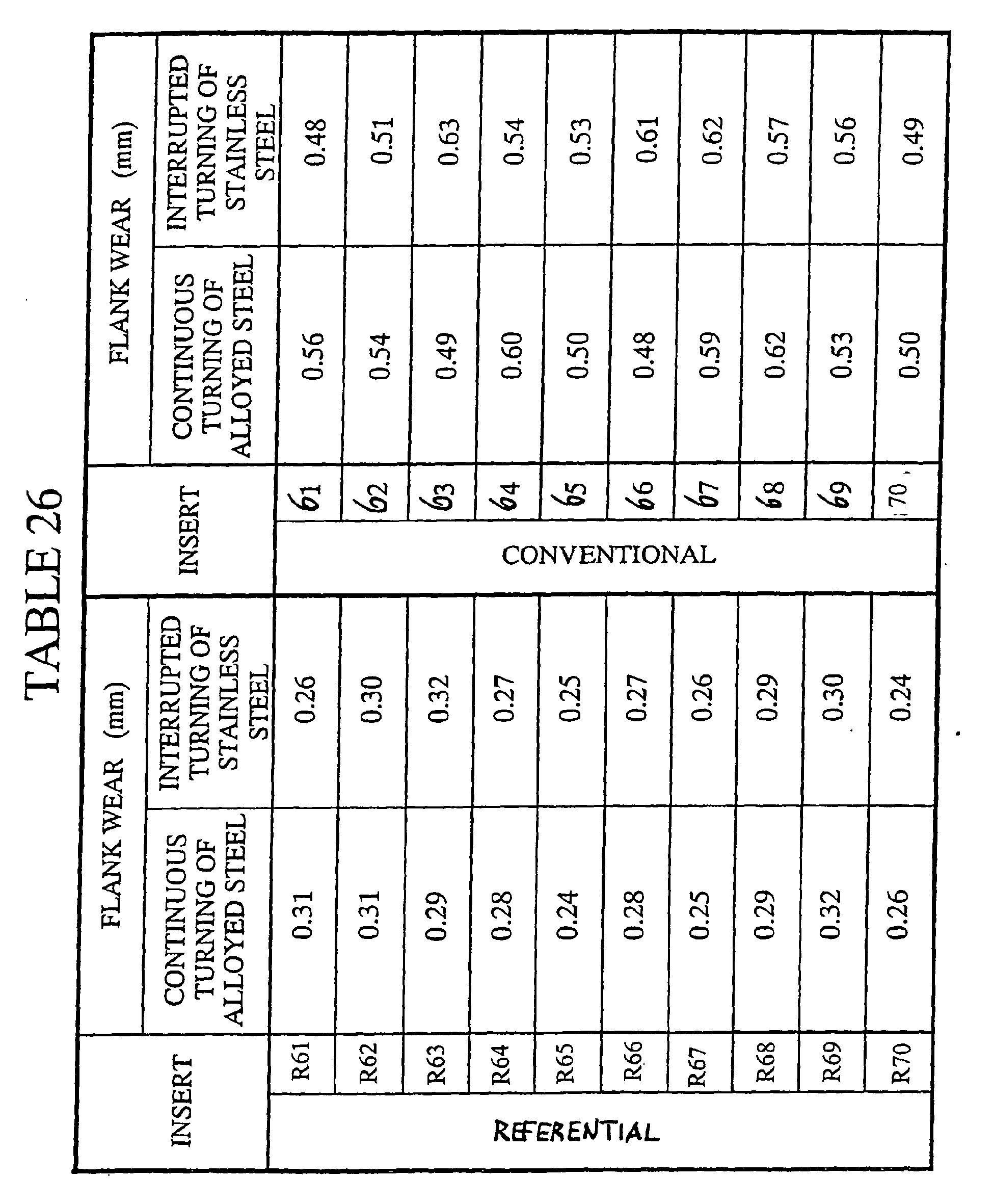
- The cutting edges of the cemented carbide insert substrates A to J were subjected to honing with the radius of 0.07 mm followed by the ultrasonic washing in an acetone solution. After careful drying, each substrate was subjected to be in the conventional chemical vapor deposition apparatus and subjected to the hard coating layer with alternated multilayer structure, each thickness of individual thin layer, alternating cycles and the total thickness are shown in Table 24 using the deposition conditions shown in Table 20. Purging status with H2 gas for 30 seconds was always inserted between the depositions of the first thin layer and the second thin layer. Reference coated cemented carbide inserts R61 to R70 were manufactured in such a manner.
- To manufacture conventional coated cemented carbide inserts for reference, the same substrates were used, and subjected to hard coating layer whose structure and thickness is shown in Table 25 using the deposition conditions shown in Table 4. Conventional coated cemented carbide inserts 61 through 70 were manufactured in such a manner.
- From the investigation of the hard coating layers using optical microscope and scanning electron microscope, the thickness of each layer was almost identical to the designed thickness.
- Furthermore, for reference coated cemented carbide inserts of the present invention R61 to R70 and conventional coated cemented carbide inserts 61 through 70, the following cutting tests were conducted. A wear width on the flank face was measured in each test. The results are shown in Table 26.
- (7-1) Cutting style: Continuous turning of alloyed steel
- Work piece: JIS SCM440 round bar
- Cutting speed: 420 m/min.
- Feed rate: 0.25 mm/rev.
- Depth of cut: 1.5 mm
- Cutting time: 5 min.
- Coolant: Dry
- (7-2) Cutting style: Interrupted turning of stainless steel
- Work piece: JIS SUS304 round bar having 4 longitudinally grooves
- Cutting speed: 230 m/min.
- Feed rate: 0.2 mm/rev.
- Depth of cut: 1.5 mm
- Cutting time: 3 min.
- Coolant: Dry
| CARBIDE SUBSTRATE | COMPOSITION (wt%) | |||||||||
| Co | TiC | ZrC | VC | TaC | NbC | Cr3C2 | TiN | TaN | WC | |
| A | 10.5 | 8 | - | - | 8 | 1.5 | - | - | - | BALANCE |
| B | 7 | - | - | - | - | - | - | - | - | BALANCE |
| C | 5.7 | - | - | - | 1.5 | 0.5 | - | - | - | BALANCE |
| D | 5.7 | - | - | - | - | - | 1 | - | - | BALANCE |
| E | 8.5 | - | 0.5 | - | - | - | 0.5 | - | - | BALANCE |
| F | 9 | - | - | - | 2.5 . | 1 | - | - | - | BALANCE |
| G | 9 | 8.5 | - | - | 8 | 3 | - | - | - | BALANCE |
| H | 11 | 8 | - | - | 4.5 | - | - | 1.5 | - | BALANCE |
| I | 12.5 | 2 | - | - | - | - | - | 1 | 2 | BALANCE |
| J | 14 | - | - | 0.2 | - | - | - | - | - | BALANCE |
| HARD COATING LAYER | COMPOSITION OF REACTIVE GAS (volume %) | AMBIENCE | |
| PRESSURE (kPa) | TEMPERATURE (°C) | ||
| TiN | TiCl4 : 4.2%, N2 : 30%, H2 : BALANCE | 25 | 980 |
| TiCN | TiCl4: 4.2%, N2: 20%, CH4: 4%, H2: BALANCE | 7 | 980 |
| α-Al2O3 | AlCl3 :2.2%, CO2 : 5.5%, HCl : 2.2%, H2S : 0.2%, H2 : BALANCE | 7 | 980 |
| κ- Al2O3 | AlCl3: 3.3%, CO2 : 4%, HCl : 2.2%, H2S : O.3%, H2: BALANCE | 7 | 980 |

| HARD COATING LAYER | COMPOSITION OF REACTIVE GAS (volume %) | AMBIENCE | |
| PRESSURE (kPa) | TEMPERATURE (°C) | ||
| TiC | TiCl4:4.2%, CH4: 8.5%, H2: BALANCE | 7 | 1020 |
| TiN (1st LAYER) | TiCl4: 4.2%, N2: 30%, H2: BALANCE | 20 | 900 |
| TiN (OTHERS) | TiCl4: 4.2%, N2: 35%, H2: BALANCE | 25 | 1040 |
| TiCN | TiCl4: 4.2%, N2: 20%, CH4: 4%, H2: BALANCE | 7 | 1020 |
| 1-TiCN | TiCl4: 4.2%, N 2: 30%, CH 3 CN : 1%, H 2: BALANCE | 7 | 900 |
| TiCO | TiCl4: 4.2%, CO: 3%, H2: BALANCE | 7 | 1020 |
| TiCNO | TiCl4: 4.2%, CO : 3%, CH4: 3%, N2: 20%, H2: BALANCE | 15 | 1020 |
| α-Al2O3 | AlCl3: 2.2%, CO2: 5.5%, HCl : 2.2%, H2S : 0.2%, H 2: BALANCE | 7 | 1000 |
| κ-Al2O3 | AlCl3: 3.3%, CO2: 5%, HCl : 2.2%, H2S : 0.2%, H2: BALANCE | 7 | 950 |
| 1-TiCN represents TiCN layer having longitudinal crystal structure |


| HARD COATING LAYER | COMPOSITION OF REACTIVE GAS (volume %) | AMBIENCE | |
| PRESSURE (kPa) | TEMPERATURE (°C) | ||
| TiN | TiCl4 : 6%, N2 : 35%, H2: BALANCE | 27 | 880 |
| κ-Al2O3 | AlCl3 : 4%, CO2: 3%, HCl: 2%, H2S : 0.3%, H2 : BALANCE | 7 | 880 |


| HARD COATING LAYER LAYER | COMPOSITION OF REACTIVE GAS (volume %) | AMBIENCE | |
| PRESSURE (kPa) | TEMPERATURE (°C) | ||
| TiN | TiCl4: 4.2%, N2 : 35%, H2: BALANCE | 25 | 960 |
| TiCN | TiCl4 : 4.2%, N2 : 20%, CH4 : 4%, H2 : BALANCE | 7 | 960 |
| HfO2 | HfCl4 : 3.5%, CO2: 6%, HCl : 1.5%, H2 : BALANCE | 7 | 960 |


Claims (7)
- A coated cemented carbide cutting tool member, comprising a hard sintered substrate and a hard coating layer deposited on the surface of said substrate, said hard coating layer comprising an alternating multilayer structure having a total thickness of between 0.5 to 20 µm and comprising a first thin layer of titanium compounds and a second thin layer of hard oxide materials whose individual thickness is between 0.01 to 0.3 µm and wherein the thickness ratio of the second thin layer to the first thin layer is set to between 2 to 4.
- The coated cemented carbide cutting tool member according to claim 1, wherein the first thin layer is made of at least one layer selected from TiC, TiCN and TiN.
- The coated cemented carbide cutting tool member according to claims 1 and 2, wherein the second thin layer is made of Al2O3.
- The coated cemented carbide cutting tool member according to claims 1 and 2, wherein the second thin layer is made of HfO2.
- The coated cemented carbide cutting tool member according to claims 1 to 4, wherein the total thickness of the hard coating layer is between 0.8 to 10 µm.
- The coated cemented carbide cutting tool member according to claim 5, wherein the total thickness of the hard coating layer is between 1 to 6 µm.
- The coated cemented carbide cutting tool member according to any of the previous claims, wherein the thickness ratio of the second thin layer to the first thin layer is set to between 2.5 to 3.5.
Applications Claiming Priority (14)
| Application Number | Priority Date | Filing Date | Title |
|---|---|---|---|
| JP2001086667A JP2002283109A (en) | 2001-03-26 | 2001-03-26 | Cutting tool made of surface coated cemented carbide having cutting blade part exhibiting superior heat- resisting plastic deformation in high-speed cutting |
| JP2001086666A JP2002283108A (en) | 2001-03-26 | 2001-03-26 | Cutting tool made of surface coating cemented carbide having cutting blade part exhibiting superior chipping resistance under double cutting condition |
| JP2001086667 | 2001-03-26 | ||
| JP2001086666 | 2001-03-26 | ||
| JP2001089144 | 2001-03-27 | ||
| JP2001089144A JP2002283110A (en) | 2001-03-27 | 2001-03-27 | Cutting tool made of surface coated cemented carbide having cutting blade part exhibiting superior chipping resistance in high-speed intermittent cutting |
| JP2001333731A JP2003136304A (en) | 2001-10-31 | 2001-10-31 | Surface coated cemented carbide cutting tool having hard coating layer exerting excellent chipping resistance in high-speed intermittent cutting |
| JP2001333731 | 2001-10-31 | ||
| JP2001341523 | 2001-11-07 | ||
| JP2001341523A JP2003136308A (en) | 2001-11-07 | 2001-11-07 | Surface coated cemented carbide cutting tool having cutting edge exerting excellent heat resistant plastic deformation in high-speed cutting |
| JP2001345742 | 2001-11-12 | ||
| JP2001345465A JP2003145310A (en) | 2001-11-12 | 2001-11-12 | Cutting tool of surface-coated cemented carbide with cutting edge part achieving excellent heat-resistant plastic deformation performance in high speed cutting |
| JP2001345742A JP2003145311A (en) | 2001-11-12 | 2001-11-12 | Cutting tool of surface-coated cemented carbide with hard coat layer achieving excellent chipping resistance in high speed discontinuous cutting |
| JP2001345465 | 2001-11-12 |
Publications (3)
| Publication Number | Publication Date |
|---|---|
| EP1245698A2 EP1245698A2 (en) | 2002-10-02 |
| EP1245698A3 EP1245698A3 (en) | 2003-01-29 |
| EP1245698B1 true EP1245698B1 (en) | 2006-09-27 |
Family
ID=27567027
Family Applications (1)
| Application Number | Title | Priority Date | Filing Date |
|---|---|---|---|
| EP02006607A Expired - Lifetime EP1245698B1 (en) | 2001-03-26 | 2002-03-22 | Coated cemented carbide cutting tool |
Country Status (5)
| Country | Link |
|---|---|
| US (1) | US6805944B2 (en) |
| EP (1) | EP1245698B1 (en) |
| CN (1) | CN1293972C (en) |
| AT (1) | ATE340879T1 (en) |
| DE (1) | DE60214922T2 (en) |
Cited By (1)
| Publication number | Priority date | Publication date | Assignee | Title |
|---|---|---|---|---|
| DE102016106952A1 (en) | 2015-04-20 | 2016-10-20 | Kennametal Inc. | CVD coated cutting set and method of making the same |
Families Citing this family (22)
| Publication number | Priority date | Publication date | Assignee | Title |
|---|---|---|---|---|
| US7913402B2 (en) | 2001-11-13 | 2011-03-29 | Acme United Corporation | Coating for cutting implements |
| WO2003041919A2 (en) * | 2001-11-13 | 2003-05-22 | Acme United Corporation | Coating for stationery cutting implements |
| US20060137971A1 (en) * | 2002-07-01 | 2006-06-29 | Larry Buchtmann | Method for coating cutting implements |
| US7934319B2 (en) * | 2002-10-28 | 2011-05-03 | Acme United Corporation | Pencil-sharpening device |
| SE526603C3 (en) | 2003-01-24 | 2005-11-16 | Sandvik Intellectual Property | Coated cemented carbide insert |
| JP2004284003A (en) | 2003-02-28 | 2004-10-14 | Mitsubishi Materials Corp | Surface-coated cermet cutting tool exhibiting excellent chipping resistance in hard coated layer |
| DE10342397B4 (en) | 2003-09-13 | 2008-04-03 | Schott Ag | Transparent protective layer for a body and its use |
| EP1536041B1 (en) * | 2003-11-25 | 2008-05-21 | Mitsubishi Materials Corporation | Coated cermet cutting tool with a chipping resistant, hard coating layer |
| US7455918B2 (en) | 2004-03-12 | 2008-11-25 | Kennametal Inc. | Alumina coating, coated product and method of making the same |
| SE528108C2 (en) | 2004-07-13 | 2006-09-05 | Sandvik Intellectual Property | Coated cemented carbide inserts, especially for turning steel, and ways of manufacturing the same |
| SE528107C2 (en) * | 2004-10-04 | 2006-09-05 | Sandvik Intellectual Property | Coated carbide inserts, especially useful for high-speed machining of metallic workpieces |
| DE102004063816B3 (en) * | 2004-12-30 | 2006-05-18 | Walter Ag | Cutting plate for a cutting tool comprises a wear-reducing coating consisting of a multiple layer base layer, an aluminum oxide multiple layer and a two-layer covering layer |
| WO2007056719A2 (en) * | 2005-11-08 | 2007-05-18 | Acme United Corporation | Mechanically assisted scissors |
| DE102006042226A1 (en) * | 2006-09-06 | 2008-03-27 | Günther & Co. GmbH | Coated twist drill |
| US8505414B2 (en) * | 2008-06-23 | 2013-08-13 | Stanley Black & Decker, Inc. | Method of manufacturing a blade |
| US8492247B2 (en) | 2010-08-17 | 2013-07-23 | International Business Machines Corporation | Programmable FETs using Vt-shift effect and methods of manufacture |
| US8769833B2 (en) | 2010-09-10 | 2014-07-08 | Stanley Black & Decker, Inc. | Utility knife blade |
| US9200371B2 (en) * | 2011-06-30 | 2015-12-01 | Oerlikon Surface Solutions Ag, Trubbach | Nano-layer coating for high performance tools |
| CN103157815B (en) * | 2011-12-08 | 2016-10-19 | 三菱综合材料株式会社 | The surface-coated cutting tool of the wearability of excellence is played in high speed heavy cut |
| US9650712B2 (en) * | 2014-12-08 | 2017-05-16 | Kennametal Inc. | Inter-anchored multilayer refractory coatings |
| JP6931453B2 (en) * | 2015-10-30 | 2021-09-08 | 三菱マテリアル株式会社 | Surface coating cutting tool with excellent chipping resistance due to the hard coating layer |
| US20180029241A1 (en) * | 2016-07-29 | 2018-02-01 | Liquidmetal Coatings, Llc | Method of forming cutting tools with amorphous alloys on an edge thereof |
Family Cites Families (18)
| Publication number | Priority date | Publication date | Assignee | Title |
|---|---|---|---|---|
| CH609380A5 (en) | 1976-07-05 | 1979-02-28 | Stellram Sa | Process for improving the wear resistance properties of an article made of hard metal, especially of a cutting tool |
| JPS59219122A (en) * | 1983-05-27 | 1984-12-10 | Sumitomo Electric Ind Ltd | Covered sintered hard alloy tool and manufacturing method thereof |
| US4749629A (en) * | 1987-01-20 | 1988-06-07 | Gte Laboratories | Ultrathin laminated oxide coatings and methods |
| US4984940A (en) | 1989-03-17 | 1991-01-15 | Kennametal Inc. | Multilayer coated cemented carbide cutting insert |
| EP0408535B1 (en) * | 1989-07-13 | 1994-04-06 | Seco Tools Ab | Multi-oxide coated carbide body and method of producing the same |
| JP3052586B2 (en) | 1992-06-25 | 2000-06-12 | 三菱マテリアル株式会社 | Surface-coated tungsten carbide based cemented carbide cutting tool with excellent chipping resistance |
| DE4239234A1 (en) * | 1992-11-21 | 1994-06-09 | Krupp Widia Gmbh | Tool and method for coating a tool body |
| JP2927181B2 (en) | 1994-05-31 | 1999-07-28 | 三菱マテリアル株式会社 | Surface coated tungsten carbide based cemented carbide cutting tool with excellent interlayer adhesion with hard coating layer |
| ATE210743T1 (en) | 1995-02-17 | 2001-12-15 | Seco Tools Ab | SINTERED CARBIDE SUBSTRATE WITH MULTI-LAYERS OF ALUMINUM |
| BR9611788A (en) * | 1995-11-30 | 1999-07-13 | Sandvik Ab | Coated cutting insert and method for making the same |
| SE9504304D0 (en) * | 1995-11-30 | 1995-11-30 | Sandvik Ab | Coated milling insert |
| JP4185172B2 (en) * | 1997-06-19 | 2008-11-26 | 住友電工ハードメタル株式会社 | Coated hard tool |
| SE518151C2 (en) | 1997-12-10 | 2002-09-03 | Sandvik Ab | Multilayer coated cutting tool |
| SE518134C2 (en) | 1997-12-10 | 2002-09-03 | Sandvik Ab | Multilayer coated cutting tool |
| WO1999040233A1 (en) | 1998-02-04 | 1999-08-12 | Osg Corporation | Multilayer coated tool |
| US20010016273A1 (en) | 1998-05-08 | 2001-08-23 | Krishnan Narasimhan | Multilayer cvd coated article and process for producing same |
| DE10017909B4 (en) | 1999-04-13 | 2009-07-23 | Mitsubishi Materials Corp. | Coated cemented carbide cutting tool element |
| ATE273405T1 (en) | 1999-11-25 | 2004-08-15 | Seco Tools Ab | COATED CUTTING INSERT FOR MILLING AND TURNING APPLICATIONS |
-
2002
- 2002-03-21 US US10/101,972 patent/US6805944B2/en not_active Expired - Lifetime
- 2002-03-22 AT AT02006607T patent/ATE340879T1/en not_active IP Right Cessation
- 2002-03-22 EP EP02006607A patent/EP1245698B1/en not_active Expired - Lifetime
- 2002-03-22 DE DE60214922T patent/DE60214922T2/en not_active Expired - Lifetime
- 2002-03-26 CN CNB021419035A patent/CN1293972C/en not_active Expired - Lifetime
Cited By (2)
| Publication number | Priority date | Publication date | Assignee | Title |
|---|---|---|---|---|
| DE102016106952A1 (en) | 2015-04-20 | 2016-10-20 | Kennametal Inc. | CVD coated cutting set and method of making the same |
| US10100405B2 (en) | 2015-04-20 | 2018-10-16 | Kennametal Inc. | CVD coated cutting insert and method of making the same |
Also Published As
| Publication number | Publication date |
|---|---|
| CN1396029A (en) | 2003-02-12 |
| EP1245698A3 (en) | 2003-01-29 |
| EP1245698A2 (en) | 2002-10-02 |
| US6805944B2 (en) | 2004-10-19 |
| DE60214922D1 (en) | 2006-11-09 |
| CN1293972C (en) | 2007-01-10 |
| US20030070305A1 (en) | 2003-04-17 |
| DE60214922T2 (en) | 2007-01-11 |
| ATE340879T1 (en) | 2006-10-15 |
Similar Documents
| Publication | Publication Date | Title |
|---|---|---|
| EP1245698B1 (en) | Coated cemented carbide cutting tool | |
| US7470296B2 (en) | Coated insert and method of making same | |
| EP1455003B1 (en) | Coated cemented carbide insert | |
| EP1288335B1 (en) | Surface-coated carbide alloy cutting tool | |
| EP1160353B1 (en) | Coated cemented carbide cutting tool member and process for producing the same | |
| US6426137B1 (en) | Coated cemented carbide cutting tool member | |
| EP1548154B1 (en) | Surface-coated cermet cutting tool with hard coating layer having excellent chipping resistance | |
| JPH10140353A (en) | Cutting, tool made of surface coated cemented carbide in which hard coating layer has excellent wear resistance | |
| EP2959994A1 (en) | Surface-coated cutting tool and process for producing same | |
| JP2001310203A (en) | Surface covered cemented carbide made cutting tool excellent in surface lubricity against chip | |
| US6638571B2 (en) | Coated cemented carbide cutting tool member and process for producing the same | |
| JP2004122269A (en) | Surface coated cermet cutting tool exhibiting superior chipping resistance under high speed heavy duty cutting | |
| JP3282592B2 (en) | Surface-coated cemented carbide cutting tool that demonstrates excellent wear resistance in high-speed cutting | |
| JPH10204639A (en) | Cutting tool made of surface-coated cemented carbide in which hard coating layer has excellent chipping resistance | |
| JPH10244405A (en) | Cutting tool made of surface-covering cemented carbide with its hard covering layer having excellent abrasion resistance | |
| JP3358530B2 (en) | Slow-away cutting insert made of surface-coated cemented carbide with excellent fracture resistance | |
| JPH10310878A (en) | Cutting tool made of surface-coated cemented carbide having hard coating layer excellent in wear resistance | |
| JP3837959B2 (en) | Surface coated tungsten carbide based cemented carbide cutting tool with excellent wear resistance due to hard coating layer | |
| JP3371796B2 (en) | Surface coated cemented carbide cutting tool with excellent fracture resistance | |
| JP3391264B2 (en) | Milling tool with excellent fracture resistance | |
| JPH09277103A (en) | Cutting tool made of surface-coated cemented carbide excellent in chipping resistance | |
| JP2001025904A (en) | Cutting tool made of surface coating tungsten carbide- base cemented carbide exerting excellent chipping resistance by its hard coating layer in intermittent heavy-load cutting | |
| JP2000158208A (en) | Surface-covering tungsten carbide group cemented carbide alloy cutting tool having its hard covering layer exhibit excellent chipping resistance | |
| JPH10130842A (en) | Cutting tool made of surface coated cement, excellent in chipping resistance | |
| JPH11323555A (en) | Throw away cutting tip made of surface-coated cemented carbide excellent in wear resistance |
Legal Events
| Date | Code | Title | Description |
|---|---|---|---|
| PUAI | Public reference made under article 153(3) epc to a published international application that has entered the european phase |
Free format text: ORIGINAL CODE: 0009012 |
|
| AK | Designated contracting states |
Kind code of ref document: A2 Designated state(s): AT BE CH CY DE DK ES FI FR GB GR IE IT LI LU MC NL PT SE TR |
|
| AX | Request for extension of the european patent |
Free format text: AL;LT;LV;MK;RO;SI |
|
| PUAL | Search report despatched |
Free format text: ORIGINAL CODE: 0009013 |
|
| AK | Designated contracting states |
Designated state(s): AT BE CH CY DE DK ES FI FR GB GR IE IT LI LU MC NL PT SE TR |
|
| AX | Request for extension of the european patent |
Extension state: AL LT LV MK RO SI |
|
| RIC1 | Information provided on ipc code assigned before grant |
Ipc: 7C 23C 16/40 B Ipc: 7C 23C 30/00 B Ipc: 7C 23C 14/08 A Ipc: 7B 23B 27/00 - |
|
| 17P | Request for examination filed |
Effective date: 20030506 |
|
| 17Q | First examination report despatched |
Effective date: 20030724 |
|
| AKX | Designation fees paid |
Designated state(s): AT BE CH CY DE DK ES FI FR GB GR IE IT LI LU MC NL PT SE TR |
|
| GRAP | Despatch of communication of intention to grant a patent |
Free format text: ORIGINAL CODE: EPIDOSNIGR1 |
|
| RIN1 | Information on inventor provided before grant (corrected) |
Inventor name: UEDA, TOSHIAKI,MITSUBISHI MATERIALS CORP. Inventor name: OSHIKA, TAKATOSHI,MITSUBISHI MATERIALS CORP. |
|
| GRAS | Grant fee paid |
Free format text: ORIGINAL CODE: EPIDOSNIGR3 |
|
| GRAA | (expected) grant |
Free format text: ORIGINAL CODE: 0009210 |
|
| AK | Designated contracting states |
Kind code of ref document: B1 Designated state(s): AT BE CH CY DE DK ES FI FR GB GR IE IT LI LU MC NL PT SE TR |
|
| PG25 | Lapsed in a contracting state [announced via postgrant information from national office to epo] |
Ref country code: AT Free format text: LAPSE BECAUSE OF FAILURE TO SUBMIT A TRANSLATION OF THE DESCRIPTION OR TO PAY THE FEE WITHIN THE PRESCRIBED TIME-LIMIT Effective date: 20060927 Ref country code: IT Free format text: LAPSE BECAUSE OF FAILURE TO SUBMIT A TRANSLATION OF THE DESCRIPTION OR TO PAY THE FEE WITHIN THE PRESCRIBED TIME-LIMIT;WARNING: LAPSES OF ITALIAN PATENTS WITH EFFECTIVE DATE BEFORE 2007 MAY HAVE OCCURRED AT ANY TIME BEFORE 2007. THE CORRECT EFFECTIVE DATE MAY BE DIFFERENT FROM THE ONE RECORDED. Effective date: 20060927 Ref country code: FI Free format text: LAPSE BECAUSE OF FAILURE TO SUBMIT A TRANSLATION OF THE DESCRIPTION OR TO PAY THE FEE WITHIN THE PRESCRIBED TIME-LIMIT Effective date: 20060927 Ref country code: LI Free format text: LAPSE BECAUSE OF FAILURE TO SUBMIT A TRANSLATION OF THE DESCRIPTION OR TO PAY THE FEE WITHIN THE PRESCRIBED TIME-LIMIT Effective date: 20060927 Ref country code: CH Free format text: LAPSE BECAUSE OF FAILURE TO SUBMIT A TRANSLATION OF THE DESCRIPTION OR TO PAY THE FEE WITHIN THE PRESCRIBED TIME-LIMIT Effective date: 20060927 Ref country code: BE Free format text: LAPSE BECAUSE OF FAILURE TO SUBMIT A TRANSLATION OF THE DESCRIPTION OR TO PAY THE FEE WITHIN THE PRESCRIBED TIME-LIMIT Effective date: 20060927 Ref country code: NL Free format text: LAPSE BECAUSE OF FAILURE TO SUBMIT A TRANSLATION OF THE DESCRIPTION OR TO PAY THE FEE WITHIN THE PRESCRIBED TIME-LIMIT Effective date: 20060927 |
|
| REG | Reference to a national code |
Ref country code: GB Ref legal event code: FG4D |
|
| REG | Reference to a national code |
Ref country code: CH Ref legal event code: EP |
|
| REG | Reference to a national code |
Ref country code: IE Ref legal event code: FG4D |
|
| REF | Corresponds to: |
Ref document number: 60214922 Country of ref document: DE Date of ref document: 20061109 Kind code of ref document: P |
|
| PG25 | Lapsed in a contracting state [announced via postgrant information from national office to epo] |
Ref country code: DK Free format text: LAPSE BECAUSE OF FAILURE TO SUBMIT A TRANSLATION OF THE DESCRIPTION OR TO PAY THE FEE WITHIN THE PRESCRIBED TIME-LIMIT Effective date: 20061227 Ref country code: SE Free format text: LAPSE BECAUSE OF FAILURE TO SUBMIT A TRANSLATION OF THE DESCRIPTION OR TO PAY THE FEE WITHIN THE PRESCRIBED TIME-LIMIT Effective date: 20061227 |
|
| PG25 | Lapsed in a contracting state [announced via postgrant information from national office to epo] |
Ref country code: ES Free format text: LAPSE BECAUSE OF FAILURE TO SUBMIT A TRANSLATION OF THE DESCRIPTION OR TO PAY THE FEE WITHIN THE PRESCRIBED TIME-LIMIT Effective date: 20070107 |
|
| NLV1 | Nl: lapsed or annulled due to failure to fulfill the requirements of art. 29p and 29m of the patents act | ||
| PG25 | Lapsed in a contracting state [announced via postgrant information from national office to epo] |
Ref country code: PT Free format text: LAPSE BECAUSE OF FAILURE TO SUBMIT A TRANSLATION OF THE DESCRIPTION OR TO PAY THE FEE WITHIN THE PRESCRIBED TIME-LIMIT Effective date: 20070313 |
|
| REG | Reference to a national code |
Ref country code: CH Ref legal event code: PL |
|
| EN | Fr: translation not filed | ||
| PLBE | No opposition filed within time limit |
Free format text: ORIGINAL CODE: 0009261 |
|
| STAA | Information on the status of an ep patent application or granted ep patent |
Free format text: STATUS: NO OPPOSITION FILED WITHIN TIME LIMIT |
|
| 26N | No opposition filed |
Effective date: 20070628 |
|
| PG25 | Lapsed in a contracting state [announced via postgrant information from national office to epo] |
Ref country code: IE Free format text: LAPSE BECAUSE OF NON-PAYMENT OF DUE FEES Effective date: 20070322 Ref country code: MC Free format text: LAPSE BECAUSE OF NON-PAYMENT OF DUE FEES Effective date: 20070331 |
|
| PG25 | Lapsed in a contracting state [announced via postgrant information from national office to epo] |
Ref country code: FR Free format text: LAPSE BECAUSE OF FAILURE TO SUBMIT A TRANSLATION OF THE DESCRIPTION OR TO PAY THE FEE WITHIN THE PRESCRIBED TIME-LIMIT Effective date: 20070525 Ref country code: GR Free format text: LAPSE BECAUSE OF FAILURE TO SUBMIT A TRANSLATION OF THE DESCRIPTION OR TO PAY THE FEE WITHIN THE PRESCRIBED TIME-LIMIT Effective date: 20061228 |
|
| PG25 | Lapsed in a contracting state [announced via postgrant information from national office to epo] |
Ref country code: FR Free format text: LAPSE BECAUSE OF FAILURE TO SUBMIT A TRANSLATION OF THE DESCRIPTION OR TO PAY THE FEE WITHIN THE PRESCRIBED TIME-LIMIT Effective date: 20060927 |
|
| PG25 | Lapsed in a contracting state [announced via postgrant information from national office to epo] |
Ref country code: CY Free format text: LAPSE BECAUSE OF FAILURE TO SUBMIT A TRANSLATION OF THE DESCRIPTION OR TO PAY THE FEE WITHIN THE PRESCRIBED TIME-LIMIT Effective date: 20060927 Ref country code: LU Free format text: LAPSE BECAUSE OF NON-PAYMENT OF DUE FEES Effective date: 20070322 |
|
| PG25 | Lapsed in a contracting state [announced via postgrant information from national office to epo] |
Ref country code: TR Free format text: LAPSE BECAUSE OF FAILURE TO SUBMIT A TRANSLATION OF THE DESCRIPTION OR TO PAY THE FEE WITHIN THE PRESCRIBED TIME-LIMIT Effective date: 20060927 |
|
| PGFP | Annual fee paid to national office [announced via postgrant information from national office to epo] |
Ref country code: IT Payment date: 20210303 Year of fee payment: 20 |
|
| PGFP | Annual fee paid to national office [announced via postgrant information from national office to epo] |
Ref country code: DE Payment date: 20210323 Year of fee payment: 20 Ref country code: GB Payment date: 20210318 Year of fee payment: 20 |
|
| REG | Reference to a national code |
Ref country code: DE Ref legal event code: R071 Ref document number: 60214922 Country of ref document: DE |
|
| REG | Reference to a national code |
Ref country code: GB Ref legal event code: PE20 Expiry date: 20220321 |
|
| PG25 | Lapsed in a contracting state [announced via postgrant information from national office to epo] |
Ref country code: GB Free format text: LAPSE BECAUSE OF EXPIRATION OF PROTECTION Effective date: 20220321 |