EP1245334A2 - Eyeglass lens processing apparatus - Google Patents
Eyeglass lens processing apparatus Download PDFInfo
- Publication number
- EP1245334A2 EP1245334A2 EP02006470A EP02006470A EP1245334A2 EP 1245334 A2 EP1245334 A2 EP 1245334A2 EP 02006470 A EP02006470 A EP 02006470A EP 02006470 A EP02006470 A EP 02006470A EP 1245334 A2 EP1245334 A2 EP 1245334A2
- Authority
- EP
- European Patent Office
- Prior art keywords
- water
- processing
- grinding
- supplying
- supply tube
- Prior art date
- Legal status (The legal status is an assumption and is not a legal conclusion. Google has not performed a legal analysis and makes no representation as to the accuracy of the status listed.)
- Granted
Links
- XLYOFNOQVPJJNP-UHFFFAOYSA-N water Substances O XLYOFNOQVPJJNP-UHFFFAOYSA-N 0.000 claims abstract description 90
- 238000001816 cooling Methods 0.000 claims abstract description 21
- 238000007599 discharging Methods 0.000 claims description 2
- 230000000694 effects Effects 0.000 description 5
- 238000010586 diagram Methods 0.000 description 4
- 230000002093 peripheral effect Effects 0.000 description 4
- 238000010276 construction Methods 0.000 description 2
- 239000000498 cooling water Substances 0.000 description 2
- 239000000428 dust Substances 0.000 description 2
- RYGMFSIKBFXOCR-UHFFFAOYSA-N Copper Chemical compound [Cu] RYGMFSIKBFXOCR-UHFFFAOYSA-N 0.000 description 1
- 229910052782 aluminium Inorganic materials 0.000 description 1
- XAGFODPZIPBFFR-UHFFFAOYSA-N aluminium Chemical compound [Al] XAGFODPZIPBFFR-UHFFFAOYSA-N 0.000 description 1
- 229910052802 copper Inorganic materials 0.000 description 1
- 239000010949 copper Substances 0.000 description 1
- 239000011521 glass Substances 0.000 description 1
- 229910052751 metal Inorganic materials 0.000 description 1
- 239000002184 metal Substances 0.000 description 1
- 229920003023 plastic Polymers 0.000 description 1
- 239000004033 plastic Substances 0.000 description 1
Images

Classifications
-
- B—PERFORMING OPERATIONS; TRANSPORTING
- B24—GRINDING; POLISHING
- B24B—MACHINES, DEVICES, OR PROCESSES FOR GRINDING OR POLISHING; DRESSING OR CONDITIONING OF ABRADING SURFACES; FEEDING OF GRINDING, POLISHING, OR LAPPING AGENTS
- B24B55/00—Safety devices for grinding or polishing machines; Accessories fitted to grinding or polishing machines for keeping tools or parts of the machine in good working condition
-
- H—ELECTRICITY
- H02—GENERATION; CONVERSION OR DISTRIBUTION OF ELECTRIC POWER
- H02K—DYNAMO-ELECTRIC MACHINES
- H02K9/00—Arrangements for cooling or ventilating
- H02K9/19—Arrangements for cooling or ventilating for machines with closed casing and closed-circuit cooling using a liquid cooling medium, e.g. oil
-
- B—PERFORMING OPERATIONS; TRANSPORTING
- B24—GRINDING; POLISHING
- B24B—MACHINES, DEVICES, OR PROCESSES FOR GRINDING OR POLISHING; DRESSING OR CONDITIONING OF ABRADING SURFACES; FEEDING OF GRINDING, POLISHING, OR LAPPING AGENTS
- B24B55/00—Safety devices for grinding or polishing machines; Accessories fitted to grinding or polishing machines for keeping tools or parts of the machine in good working condition
- B24B55/02—Equipment for cooling the grinding surfaces, e.g. devices for feeding coolant
-
- B—PERFORMING OPERATIONS; TRANSPORTING
- B24—GRINDING; POLISHING
- B24B—MACHINES, DEVICES, OR PROCESSES FOR GRINDING OR POLISHING; DRESSING OR CONDITIONING OF ABRADING SURFACES; FEEDING OF GRINDING, POLISHING, OR LAPPING AGENTS
- B24B9/00—Machines or devices designed for grinding edges or bevels on work or for removing burrs; Accessories therefor
- B24B9/02—Machines or devices designed for grinding edges or bevels on work or for removing burrs; Accessories therefor characterised by a special design with respect to properties of materials specific to articles to be ground
- B24B9/06—Machines or devices designed for grinding edges or bevels on work or for removing burrs; Accessories therefor characterised by a special design with respect to properties of materials specific to articles to be ground of non-metallic inorganic material, e.g. stone, ceramics, porcelain
- B24B9/08—Machines or devices designed for grinding edges or bevels on work or for removing burrs; Accessories therefor characterised by a special design with respect to properties of materials specific to articles to be ground of non-metallic inorganic material, e.g. stone, ceramics, porcelain of glass
- B24B9/14—Machines or devices designed for grinding edges or bevels on work or for removing burrs; Accessories therefor characterised by a special design with respect to properties of materials specific to articles to be ground of non-metallic inorganic material, e.g. stone, ceramics, porcelain of glass of optical work, e.g. lenses, prisms
-
- H—ELECTRICITY
- H02—GENERATION; CONVERSION OR DISTRIBUTION OF ELECTRIC POWER
- H02K—DYNAMO-ELECTRIC MACHINES
- H02K7/00—Arrangements for handling mechanical energy structurally associated with dynamo-electric machines, e.g. structural association with mechanical driving motors or auxiliary dynamo-electric machines
- H02K7/14—Structural association with mechanical loads, e.g. with hand-held machine tools or fans
Definitions
- the present invention relates to an eyeglass lens processing apparatus for processing a peripheral edge of an eyeglass lens.
- An apparatus for processing a peripheral edge of an eyeglass lens has, inside the apparatus, a grinding wheel (processing tool) for grinding (processing) a peripheral edge of the lens and a grinding-wheel rotating (processing tool driving) motor for rotatively driving the grinding wheel (processing tool). Since a large driving force is required in order to rotatively drive a heavy grinding wheel (processing tool), a grinding-wheel rotating motor with an output of about 400 W or more is frequently used.
- grinding water cutting water is supplied to cool the portion of the lens being ground (processed) and remove the grinding (processing) debris.
- a grinding-wheel rotating motor having a large output If a grinding-wheel rotating motor having a large output is used, the amount of heat generated becomes large, so that it becomes necessary to cool the motor.
- As a system of cooling the motor there is air cooling using a fan, but air cooling using the fan is inferior in its cooling effect as compared with water cooling.
- the fan is used, the grinding (processing) dust produced at the time of lens grinding (processing) is sucked, which can cause a fault in mechanical portions of the interior of the apparatus.
- the object of the invention is to provide an eyeglass lens processing apparatus in which the effect of cooling the lens grinding (processing) motor is enhanced without making the configuration of the apparatus complex.
- the present invention provides the followings:
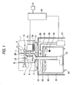
- Fig. 1 is a schematic diagram of a lens processing apparatus in accordance with a first embodiment of the invention.
- the lens processing apparatus is mainly comprised of a main body 1 of the processing apparatus, a table 40 for placing the main body 1 thereon, and a tank unit 20 disposed inside the table 40 to circulate grinding water.
- a grinding section 10 which includes two lens rotating shafts 2R and 2L for holding a subject lens LE, a carriage section 3 to which the shafts 2R and 2L are rotatably attached, a grinding wheel 5 attached to a rotating shaft of a motor 12 to grind the peripheral edge of the lens LE, and so on, is disposed inside the housing of the main body 1.
- the carriage section 3 is arranged to be movable in the axial direction of the shafts 2R and 2L and to be relatively movable with respect to the grinding wheel 5. It should be noted that since the known construction in JP-A-5-212661 (U.S. Pat. No. 5,347,762, Re. 35,898) and the like by the assignee of this application can be used as this grinding section 10, a detailed description thereof will be omitted.
- the grinding wheel 5 is made up of three grinding wheels including a rough grinding wheel for plastics, a rough grinding wheel for glass, and a finishing grinding wheel having a beveling V-groove and a flat grinding surface, and is rotated by the motor 12.
- the motor 12 is mounted on an unillustrated base of the main body 1 so as to come into contact with a water-cooled cooler 13 for cooling the generated heat.
- the cooler 13 is formed of a metallic member (aluminum, copper or the like) having excellent heat conductivity, and a channel, in which grinding water flows to be used as cooling water, is formed in its interior.
- a grinding chamber 9 is formed inside the main body 1 by a waterproof cover 8 in such a manner as to surround the lens LE held by the lens rotating shafts 2R and 2L as well as the grinding wheel 5.
- a nozzle 11 for jetting the grinding water extends in this grinding chamber 9.
- Reference numeral 22 denotes a storage tank for storing the grinding water.
- a water suction pipe 34 extending downward is attached to a cover 23 of the tank 22, and a coarse mesh-like filter 35 is attached to a lower end of the pipe 34.
- a water suction tube 33 is connected to an upper end of the pipe 34 projecting from an upper surface of the cover 23, while the other end of the water suction tube 33 is connected to a suction pump 31.
- a water supply tube 36 is connected to the suction pump 31, while the other end of the water supply tube 36 is connected to an inlet port 13a of the cooler 13.
- a discharge port 13b of the cooler 13 and the nozzle 11 are connected by a water supply tube 15.
- the grinding water sucked from inside the tank 22 through the water suction pipe 34 and the water suction tube 33 by the driving of the pump 31 is fed to the nozzle 11 through the water supply tube 36, the cooler 13, and the water supply tube 15.
- a drain pipe 21 is connected to a drain port located in a lower portion of the cover 8, and the drain pipe 21 extends to the interior of the storage tank 22.
- a removable filter 25 which also serves as a bag for collecting the grinding debris is attached to a lower end of the drain pipe 21.
- Reference numeral 50 denotes a control unit provided in the main body 1. Connected to the control unit 50 are the pump 31, the motor 12, unillustrated other motors of the grinding section 10, and the like.
- the motor 12 is driven by the control unit 50 to rotate the grinding wheel 5.
- the pump 31 is driven, and the grinding water sucked from the tank 22 is fed to the cooler 13 through the water supply tube 36.
- the heat generated from the motor 12 is transmitted to the cooler 13 through a metal frame of the motor 12 itself, and is radiated to the grinding water at the internal channel of the cooler 13. Consequently, the heated motor 12 is cooled.
- the grinding water which passed through the interior of the cooler 13 is sent to the nozzle 11 through the water supply tube 15, and is jetted into the grinding chamber 9.
- the jetted grinding water and the grinding debris produced during the grinding are received by the cover 8, and are drained into the tank 22 through the drain pipe 21.
- the grinding debris are collected by the filter 25.
- the grinding water stored in the tank 22 is sucked again by the pump 31, and is recirculated in the above-described manner.
- the motor 12 since the grinding water is also used as cooling water for the motor 12, the motor 12 can be cooled by a simple arrangement without substantially changing the overall configuration of the apparatus.
- water cooling is free of the problem of suction of the grinding dust by a fan, and makes it possible to compact the motor compact since the cooling effect is higher than air cooling using the fan.
- Fig. 2 is a diagram illustrating a second embodiment. Those elements that are equivalent to those of the first embodiment are denoted by the same reference numerals.
- the water supply tube 36 is branched into two water supply tubes 62 and 63 by a brancher 61.
- the water supply tube 62 is connected to the nozzle 11, while the water supply tube 63 is connected to the inlet port 13a of the cooler 13.
- the grinding water which passed through the interior of the cooler 13 is directly released into the cover 8 by a water supply tube 64.
- the paths of the grinding water are made independent on the nozzle 11 side and the cooler 13 side, respectively, sufficient effects can be obtained in the cooling of the motor 12 and the cooling of the ground portion of the lens LE.
- the processing tool for processing the lens is not limited to a grinding wheel, and it is possible to use a known processing tool, and that the case where a driving means such as a motor for driving that processing tool is cooled by the grinding (processing) water is included in the invention.
Landscapes
- Engineering & Computer Science (AREA)
- Mechanical Engineering (AREA)
- Power Engineering (AREA)
- Chemical & Material Sciences (AREA)
- Ceramic Engineering (AREA)
- Inorganic Chemistry (AREA)
- Grinding-Machine Dressing And Accessory Apparatuses (AREA)
- Grinding And Polishing Of Tertiary Curved Surfaces And Surfaces With Complex Shapes (AREA)
Abstract
Description
Claims (6)
- An eyeglass lens processing apparatus comprising:a processing tool (5) for processing a periphery of a lens;driving means (12) for driving the processing tool;a processing chamber (9) in which the processing tool is disposed;water supplying means for supplying lens processing water into the processing chamber; andcooling means for cooling the driving means using the water supplied by the water supplying means.
- The apparatus of claim 1, wherein:the cooling means includes a water-cooled cooler (13); andthe water supplying means includes a first water supply tube (36) for supplying the water to the cooler.
- The apparatus of claim 2, wherein the water supplying means includes a nozzle (11) for jetting the water into the processing chamber, and a second water supply tube (15) for supplying the water from the cooler to the nozzle.
- The apparatus of claim 2, wherein the water supplying means includes a nozzle (11) for jetting the water into the processing chamber, a second water supply tube (62) for supplying the water, supplied by the first water supply tube, to the nozzle, and a third water supply tube (63) for supplying the water, supplied by the first water supply tube, to the cooler.
- The apparatus of claim 2, wherein the water supplying means includes a water storage tank (22), and a pump (31) for sucking the water inside the tank and supplying the sucked water to the first water supply tube.
- The apparatus of claim 5, further comprising:drain means (21) for discharging the water, supplied into the processing chamber, into the tank.
Applications Claiming Priority (2)
| Application Number | Priority Date | Filing Date | Title |
|---|---|---|---|
| JP2001087109 | 2001-03-26 | ||
| JP2001087109A JP2002283183A (en) | 2001-03-26 | 2001-03-26 | Spectacle lens machining device |
Publications (3)
| Publication Number | Publication Date |
|---|---|
| EP1245334A2 true EP1245334A2 (en) | 2002-10-02 |
| EP1245334A3 EP1245334A3 (en) | 2004-01-21 |
| EP1245334B1 EP1245334B1 (en) | 2007-06-06 |
Family
ID=18942394
Family Applications (1)
| Application Number | Title | Priority Date | Filing Date |
|---|---|---|---|
| EP02006470A Expired - Lifetime EP1245334B1 (en) | 2001-03-26 | 2002-03-22 | Eyeglass lens processing apparatus |
Country Status (4)
| Country | Link |
|---|---|
| EP (1) | EP1245334B1 (en) |
| JP (1) | JP2002283183A (en) |
| DE (1) | DE60220468T2 (en) |
| ES (1) | ES2288175T3 (en) |
Cited By (3)
| Publication number | Priority date | Publication date | Assignee | Title |
|---|---|---|---|---|
| EP1348518A3 (en) * | 2002-03-28 | 2004-03-17 | Nidek Co., Ltd. | Grinding water tank apparatus, and eyeglass lens machining apparatus having the same |
| EP2954989A1 (en) * | 2014-06-11 | 2015-12-16 | La Chiara S.r.l. | Coolant-filtering apparatus for lens-processing machine tolls |
| CN108788989A (en) * | 2018-09-03 | 2018-11-13 | 上海光和光学制造大丰有限公司 | A kind of glass grinding device on vehicle mounted guidance |
Families Citing this family (4)
| Publication number | Priority date | Publication date | Assignee | Title |
|---|---|---|---|---|
| JP6347317B2 (en) * | 2014-01-14 | 2018-06-27 | 株式会社ニデック | Eyeglass lens processing apparatus and eyeglass lens processing program |
| JP6523872B2 (en) * | 2015-08-27 | 2019-06-05 | 株式会社ディスコ | Grinding device |
| CN108972345A (en) * | 2018-07-20 | 2018-12-11 | 南京航空航天大学 | A kind of grinding machine cooling nozzles lifting device and its operation process |
| WO2026070805A1 (en) * | 2024-09-30 | 2026-04-02 | 株式会社ニデック | Eyeglass lens processing treatment system and grinding water treatment device for eyeglass lens processing |
Family Cites Families (4)
| Publication number | Priority date | Publication date | Assignee | Title |
|---|---|---|---|---|
| US2236714A (en) * | 1938-08-04 | 1941-04-01 | Metzger Reinhardt Frederick | Apparatus for grinding lenses |
| US2871627A (en) * | 1957-05-22 | 1959-02-03 | Robinson Houchin Inc | Lens edging machine |
| WO1998009770A1 (en) * | 1996-09-04 | 1998-03-12 | Wernicke & Co. Gmbh | Polishing machine for spectacle lenses |
| JP3807704B2 (en) * | 1998-09-30 | 2006-08-09 | 株式会社ジェイテクト | Grinding machine equipped with a grinding wheel correction device |
-
2001
- 2001-03-26 JP JP2001087109A patent/JP2002283183A/en not_active Withdrawn
-
2002
- 2002-03-22 EP EP02006470A patent/EP1245334B1/en not_active Expired - Lifetime
- 2002-03-22 DE DE60220468T patent/DE60220468T2/en not_active Expired - Fee Related
- 2002-03-22 ES ES02006470T patent/ES2288175T3/en not_active Expired - Lifetime
Cited By (3)
| Publication number | Priority date | Publication date | Assignee | Title |
|---|---|---|---|---|
| EP1348518A3 (en) * | 2002-03-28 | 2004-03-17 | Nidek Co., Ltd. | Grinding water tank apparatus, and eyeglass lens machining apparatus having the same |
| EP2954989A1 (en) * | 2014-06-11 | 2015-12-16 | La Chiara S.r.l. | Coolant-filtering apparatus for lens-processing machine tolls |
| CN108788989A (en) * | 2018-09-03 | 2018-11-13 | 上海光和光学制造大丰有限公司 | A kind of glass grinding device on vehicle mounted guidance |
Also Published As
| Publication number | Publication date |
|---|---|
| EP1245334B1 (en) | 2007-06-06 |
| EP1245334A3 (en) | 2004-01-21 |
| JP2002283183A (en) | 2002-10-03 |
| DE60220468D1 (en) | 2007-07-19 |
| ES2288175T3 (en) | 2008-01-01 |
| DE60220468T2 (en) | 2008-02-07 |
Similar Documents
| Publication | Publication Date | Title |
|---|---|---|
| EP1245334B1 (en) | Eyeglass lens processing apparatus | |
| CN211681392U (en) | Motorcycle accessory machining device easy for cleaning scraps | |
| US2260949A (en) | Portable belt sander | |
| JP2010030007A (en) | Grinder and scratch detection apparatus | |
| CN110561245A (en) | dustproof handheld grinding equipment | |
| CN108188867A (en) | A kind of eyeglass refiner | |
| JP4559177B2 (en) | Polishing machine cover and polishing machine | |
| CN115041749B (en) | Cutting device is used in railway accessory production | |
| CN215659364U (en) | Hand-held type grinding device for architectural decoration with function is collected to dust | |
| CN115890411A (en) | Grinding device is used in vehicle accessory processing | |
| CN212351566U (en) | Waterproof stopper production line stock surface refines processing apparatus | |
| CN220902705U (en) | Numerical control grinding machine for machining drill bit by feeding and discharging in parallel | |
| CN217552138U (en) | Water-cooling grinding machine with wider polishing area | |
| CN218613290U (en) | Polishing machine with semi-automatic feeding function | |
| CN115625592A (en) | Machining grinding machine with chip cleaning and recycling functions and operation method | |
| CN115056032A (en) | Aluminum alloy material processing and cutting integrated device and process thereof | |
| JP5615735B2 (en) | Machine Tools | |
| CN220481287U (en) | Lathe cutter burnishing device | |
| CN208629134U (en) | A kind of sander | |
| CN216913289U (en) | Hand-held type angle mill | |
| CN219485262U (en) | Basin grinding device | |
| CN219945668U (en) | A fine grinding equipment | |
| JP4037063B2 (en) | Grinding water tank unit for spectacle lens processing and spectacle lens processing apparatus provided with the same | |
| CN216422077U (en) | Workpiece surface polishing equipment | |
| CN222831455U (en) | Dustproof grinding machine for mold production |
Legal Events
| Date | Code | Title | Description |
|---|---|---|---|
| PUAI | Public reference made under article 153(3) epc to a published international application that has entered the european phase |
Free format text: ORIGINAL CODE: 0009012 |
|
| AK | Designated contracting states |
Kind code of ref document: A2 Designated state(s): AT BE CH CY DE DK ES FI FR GB GR IE IT LI LU MC NL PT SE TR |
|
| AX | Request for extension of the european patent |
Free format text: AL;LT;LV;MK;RO;SI |
|
| PUAL | Search report despatched |
Free format text: ORIGINAL CODE: 0009013 |
|
| AK | Designated contracting states |
Kind code of ref document: A3 Designated state(s): AT BE CH CY DE DK ES FI FR GB GR IE IT LI LU MC NL PT SE TR |
|
| AX | Request for extension of the european patent |
Extension state: AL LT LV MK RO SI |
|
| 17P | Request for examination filed |
Effective date: 20040528 |
|
| AKX | Designation fees paid |
Designated state(s): DE ES FR GB |
|
| GRAP | Despatch of communication of intention to grant a patent |
Free format text: ORIGINAL CODE: EPIDOSNIGR1 |
|
| GRAS | Grant fee paid |
Free format text: ORIGINAL CODE: EPIDOSNIGR3 |
|
| GRAA | (expected) grant |
Free format text: ORIGINAL CODE: 0009210 |
|
| AK | Designated contracting states |
Kind code of ref document: B1 Designated state(s): DE ES FR GB |
|
| REG | Reference to a national code |
Ref country code: GB Ref legal event code: FG4D |
|
| REF | Corresponds to: |
Ref document number: 60220468 Country of ref document: DE Date of ref document: 20070719 Kind code of ref document: P |
|
| ET | Fr: translation filed | ||
| REG | Reference to a national code |
Ref country code: ES Ref legal event code: FG2A Ref document number: 2288175 Country of ref document: ES Kind code of ref document: T3 |
|
| PLBE | No opposition filed within time limit |
Free format text: ORIGINAL CODE: 0009261 |
|
| STAA | Information on the status of an ep patent application or granted ep patent |
Free format text: STATUS: NO OPPOSITION FILED WITHIN TIME LIMIT |
|
| 26N | No opposition filed |
Effective date: 20080307 |
|
| PGFP | Annual fee paid to national office [announced via postgrant information from national office to epo] |
Ref country code: GB Payment date: 20080326 Year of fee payment: 7 |
|
| PGFP | Annual fee paid to national office [announced via postgrant information from national office to epo] |
Ref country code: FR Payment date: 20080311 Year of fee payment: 7 Ref country code: ES Payment date: 20080331 Year of fee payment: 7 Ref country code: DE Payment date: 20080407 Year of fee payment: 7 |
|
| GBPC | Gb: european patent ceased through non-payment of renewal fee |
Effective date: 20090322 |
|
| REG | Reference to a national code |
Ref country code: FR Ref legal event code: ST Effective date: 20091130 |
|
| PG25 | Lapsed in a contracting state [announced via postgrant information from national office to epo] |
Ref country code: DE Free format text: LAPSE BECAUSE OF NON-PAYMENT OF DUE FEES Effective date: 20091001 |
|
| PG25 | Lapsed in a contracting state [announced via postgrant information from national office to epo] |
Ref country code: GB Free format text: LAPSE BECAUSE OF NON-PAYMENT OF DUE FEES Effective date: 20090322 Ref country code: FR Free format text: LAPSE BECAUSE OF NON-PAYMENT OF DUE FEES Effective date: 20091123 |
|
| REG | Reference to a national code |
Ref country code: ES Ref legal event code: FD2A Effective date: 20090323 |
|
| PG25 | Lapsed in a contracting state [announced via postgrant information from national office to epo] |
Ref country code: ES Free format text: LAPSE BECAUSE OF NON-PAYMENT OF DUE FEES Effective date: 20090323 |