EP1244002A2 - Information processing apparatus having cooling air passage with a plurality of heat generating components interposed - Google Patents
Information processing apparatus having cooling air passage with a plurality of heat generating components interposed Download PDFInfo
- Publication number
- EP1244002A2 EP1244002A2 EP01122232A EP01122232A EP1244002A2 EP 1244002 A2 EP1244002 A2 EP 1244002A2 EP 01122232 A EP01122232 A EP 01122232A EP 01122232 A EP01122232 A EP 01122232A EP 1244002 A2 EP1244002 A2 EP 1244002A2
- Authority
- EP
- European Patent Office
- Prior art keywords
- cooling air
- heat generating
- generating components
- housing
- processing apparatus
- Prior art date
- Legal status (The legal status is an assumption and is not a legal conclusion. Google has not performed a legal analysis and makes no representation as to the accuracy of the status listed.)
- Withdrawn
Links
Images




Classifications
-
- H—ELECTRICITY
- H05—ELECTRIC TECHNIQUES NOT OTHERWISE PROVIDED FOR
- H05K—PRINTED CIRCUITS; CASINGS OR CONSTRUCTIONAL DETAILS OF ELECTRIC APPARATUS; MANUFACTURE OF ASSEMBLAGES OF ELECTRICAL COMPONENTS
- H05K7/00—Constructional details common to different types of electric apparatus
- H05K7/20—Modifications to facilitate cooling, ventilating, or heating
- H05K7/20709—Modifications to facilitate cooling, ventilating, or heating for server racks or cabinets; for data centers, e.g. 19-inch computer racks
- H05K7/20718—Forced ventilation of a gaseous coolant
- H05K7/20727—Forced ventilation of a gaseous coolant within server blades for removing heat from heat source
-
- G—PHYSICS
- G06—COMPUTING OR CALCULATING; COUNTING
- G06F—ELECTRIC DIGITAL DATA PROCESSING
- G06F1/00—Details not covered by groups G06F3/00 - G06F13/00 and G06F21/00
- G06F1/16—Constructional details or arrangements
- G06F1/18—Packaging or power distribution
-
- G—PHYSICS
- G06—COMPUTING OR CALCULATING; COUNTING
- G06F—ELECTRIC DIGITAL DATA PROCESSING
- G06F1/00—Details not covered by groups G06F3/00 - G06F13/00 and G06F21/00
- G06F1/16—Constructional details or arrangements
- G06F1/18—Packaging or power distribution
- G06F1/183—Internal mounting support structures, e.g. for supporting printed circuit boards
-
- G—PHYSICS
- G06—COMPUTING OR CALCULATING; COUNTING
- G06F—ELECTRIC DIGITAL DATA PROCESSING
- G06F1/00—Details not covered by groups G06F3/00 - G06F13/00 and G06F21/00
- G06F1/16—Constructional details or arrangements
- G06F1/20—Cooling means
Definitions
- the present invention relates to an information processing apparatus with a plurality of heat generating components such as microprocessors housed inside the housing, and more specifically to the construction of cooling the heat generating components.
- the rack-mount type server comprises a stand called a cabinet rack and a server body that is supported by the stand.
- the server body has a box-form housing and inside this housing, microprocessors, CD-ROM drive, power supply unit, a plurality of hard disk drives, and other various functional parts housed in a lump.
- the server body that handles a large volume of data has two microprocessors equipped for increased processing speed. These microprocessors are mounted side by side on a main circuit board called a motherboard.
- the microprocessors cannot avoid an increase of heat generation as the processing speed increases. Consequently, in order to secure the stable operation of the server body, it is necessary to increase the heat radiation capacity of microprocessors.
- heat sinks are mounted to the microprocessors and an electrically-operated fan is housed inside the housing. The electrically-operated fan supplies cooling air to the heat sinks and microprocessors in accord with the operating condition of the server body. By this, the microprocessors are forcibly cooled.
- the two microprocessors are placed side by side in the condition so close to each other in order to downsize the main circuit board that they cannot be said that they are thermally insulated. Consequently, the heat discharged from one microprocessor may be transmitted to the other microprocessor. As a result, even if cooling air is fed to the heat sink that deprives each microprocessor of the heat, cooling air heated by exchanging heat with the one heat sink may be blown on the other heat sink or microprocessor.
- the two microprocessors exert thermal influences to each other and even though these two microprocessors are made to forcibly air-cool, the desired cooling effects are unable to be obtained from the microprocessors.
- an information processing apparatus comprises; a duct that forms a cooling air passage through which cooling air flows; and a plurality of heat generating components which are cooled by the cooling air that flows the cooling air passage.
- the heat generating components are arranged displaced relative to the flowing direction of the cooling air as well as displaced one another in the direction crossing the cooling air flowing direction.
- An information processing apparatus comprises; a circuit board housed in a housing and equipped with a mount surface; a plurality of heat generating components arranged and mounted on the mount surface of the circuit board; a duct installed to the mount surface of the circuit board, the duct having formed an independent cooling air passage in the housing inside and the heat generating components having been located in the cooling air passage; and an air feeding means for feeding cooling air to the cooling air passage.
- the heat generating components are arranged displaced relative to the flowing direction of the cooling air as well as displaced one another in the direction crossing the cooling air flowing direction.
- the cooling air that flows the cooling air passage has the flow direction guided by the duct, and therefore, the cooling air flow is not diffused around a plurality of heat generating components but the cooling air can be concentratedly guided to these heat generating components.
- the heat generating components do not overlap along the cooling air flow direction and high-temperature cooling air heated by the heat exchange with other heat generating component is not guided to any of the heat generating component.
- the outer peripheral surfaces of these heat generating components are not brought closer as is the case when the heat generating components are arranged in parallel. Consequently, the outer peripheral surfaces of the heat generating components can be exposed to the cooling air passage over a wide range, and the sufficiently wide contact area can be secured between individual heat generating components and cooling air.
- adjacent heat generating components do not exert thermal influences to one another and heat generating components can be efficiently cooled without increasing the air volume of cooling air.
- an information processing apparatus comprises; a housing equipped with a removable top plate; a circuit board which is housed in the housing and which has a mount surface that opposes to the top plate; a duct that is removably housed in the housing inside, the duct having formed a cooling air passage independently from the housing inside on the mount surface of the circuit board; a plurality of heat generating components removably mounted on the mount surface of the circuit board and cooled by cooling air that flows the cooling air passage, the heat generating components having been arranged relative to the flowing direction of the cooling air as well as displaced one another in the direction crossing the cooling air flowing direction; and a power supply unit housed inside the housing, the power supply unit having been installed to the place deviated from the duct.
- the power supply unit is housed inside the housing at the position deviated from the duct, the heat generating components can be exposed on the circuit board only by the operation to remove the top plate of the housing and the duct. Consequently, for example, even if the heat generating components must be replaced, it is no longer necessary to remove a heavy and large power supply unit from the housing and assemble it to the housing each time. Consequently, the operability at the time of removing and mounting heat generating components can be improved.
- FIG. 1 discloses a rack-mount type server 1 as an information processing apparatus.
- Server 1 is equipped with a stand 2 called a cabinet rack.
- the stand 2 is formed into a box shape of a longer side extending along the perpendicular direction.
- the stand 2 comprises a pedestal 4 installed on a floor surface 3, four columns 5a to 5d perpendicularly erected from four corners of the pedestal 4, and a top plate 6, right and left side plates 7, and a rear plate 8 that are fixed to the columns 5a to 5d.
- These pedestal 4, top plate 6, right and left side plates 7, and rear plate 8 define an equipment storage chamber 9 in the stand 2.
- the frame 2 has an opening 10 on the front surface.
- the opening 10 extends in the height direction of the stand 2 and is continuous with the equipment storage chamber 9. This opening 10 is opened and closed by a door 11 mounted to the front end of the stand 2.
- the two columns 5a, 5b located at the front end of the pedestal 4 face each other with the opening 10 in-between.
- Mount frames 13 are fixed to the columns 5a, 5b, respectively.
- the mount frames 13 extends along the height direction of the stand 2, and exposes to the opening 10. Consequently, a width W1 of the opening 10 is determined by the arrangement intervals of the mount frames 13, and in the conventional standard 19-inch stand, the width W1 of the opening 10 is set to about 450 mm.
- rear frames 14 are fixed to the two columns 5c, 5d that are situated at the rear end of the pedestal 4, respectively.
- the rear frames 14 extends along the height direction of the stand 2.
- the rear frames 14 and the mount frames 13 face each other in the depth direction of the stand 2.
- Each of the mount frames 13 and the rear frames 14 has a large number of through holes 15, respectively. These through holes 15 are arranged in one line with intervals provided in the height direction of the stand 2.
- each bracket 17 has a flat plate form.
- Each bracket 17 has a first flange section 18 that is butted to each mount frame 13 and a second flange section 19 that is butted to each rear frame 14.
- the first and the second flange sections 18, 19 are fixed to the mount frame 13 and the rear frame 14, respectively, via a plurality of screws 20 in the height position corresponding to the required through holes 15.
- brackets 17 are held horizontally along the depth direction of the stand 2 and at the same time faces each other in the width direction of the stand 2.
- the brackets 17 are located individually in three positions that are spaced in the height direction of the stand 2.
- a stopper 21 is fixed to each bracket 17.
- the stopper 21 protrudes into the equipment storage chamber 9 at the intermediate section along the depth direction of the stand 2.
- An engaging hole 22 is formed in the distal end section of each stopper 21.
- each shelf 25 is arranged horizontally across brackets 17.
- Each shelf 25 has right and left side plates 26 that rise along the brackets 17.
- the shelves 25 are removably housed in the equipment storage chamber 9 through the opening 10 of the stand 2. Consequently, a width W2 of each shelf 25 is set to 440 mm or less, which is smaller than the width W1 of the opening 10.
- each side plate 26 of the shelf 25 has a pair of tongue-piece sections 27a, 27b bent outwards at right angles at the front end section.
- the tongue-piece sections 27a, 27b are vertically arranged so as to face the their corresponding mount frame 13.
- the screws 20 that fasten each bracket 17 to its corresponding mount frame 13 are situated between the tongue-piece sections 27a, 27b.
- the tongue-piece sections 27a, 27b are fixed to each bracket 17 via decorative screws 28a, 28b.
- the decorative screws 28a, 28b pass through the through holes 15 and are driven into the first flange section 18 of each bracket 17.
- the front end section of each shelf 25 is fixed to the desired height position of the mount frames 13 via the tongue-piece sections 27a, 27b.
- each side plate 26 of each shelf 25 has a flange section 29 bent inwards at right angles at the rear end section.
- the flange section 29 faces the stopper 21 of the bracket 17 each other, and an engaging pin 30 protruding towards the stopper 21 is fixed to this flange section 29.
- the engaging pin 30 is fitted in the engaging hole 22 of the stopper 21, and by this, the rear end section of each shelf 25 is held on each bracket 17.
- the equipment storage chamber 9 of the stand 2 houses, for example, two server bodies 32 and four extension units 33.
- the two server bodies 32 are arranged side by side in the width direction on the shelf 25 at the top tier.
- the four extension units 33 are provided for increasing the storage capacity of the server bodies 32.
- These extension units 33 are arranged in pairs side by side in the width direction on two shelves 25 below the server bodies 32.
- FIG. 7 to FIG. 9 disclose the overall shape of each server body 32 as the information processing apparatus.
- Each server body 32 has a metal housing 34.
- the housing 34 is formed in a long and narrow rectangular box shape extending in the depth direction of the stand 2, and a width W3 is set to one half the width W2 of each shelf 25. Consequently, the respective housing 34 of each pair of server bodies 32 are arranged in the width direction of each shelf 25 on the shelf 25, and are held between the side plates 26 of the shelf 25.
- the extension unit 33 has a metal housing 35 that houses, for example, four hard disk drives (not illustrated).
- the housing 34 of each server body 32 and the housing 35 of each extension unit 33 have the width W3, depth D, and height H set equal to each other. Consequently, it is able to arrange the server body 32 and the extension unit 33 side by side on one shelf 25, thereby rendering itself capable for accommodating various application forms.
- the housing 34 of the server body 32 comprises a housing body 36 and a top plate 37.
- the housing body 36 has a rectangular shape bottom plate 38, right and left side plates 39a, 39b, and a rear plate 40.
- the bottom plate 38 is laid on top of the shelf 25.
- the side plates 39a, 39b rise at right angles from the right and left side edge sections of the bottom plate 38.
- the rear plate 50 lies across the rear edge section of side plates 39a, 39b.
- a pair of exhaust holes 41a, 41b are opened side by side.
- the top plate 37 is removably screwed to the upper end section of the side plates 39a, 39b and the upper end section of the rear plate 40 and faces the bottom plate 38.
- These top plate 37, bottom plate 38, side plates 39a, 39b, and rear plate 40 form a housing chamber 42 in the housing 34.
- the housing 34 has a rectangular loading gate 43 at the front end.
- the loading gate 43 has an opening that extends horizontally in the width direction of the housing 34 and continuous with the housing chamber 42.
- a front door 45 that opens and closes the loading gate 43 is arranged at the front end section of the housing 34.
- the front door 45 has a rectangular plate form that agrees with the opening shape of the loading gate 43.
- the front door 45 has a large number of vent holes 46 and slit-form opening sections 47.
- the opening section 47 extends in the width direction of the housing 34 at the top of the left half of the front door 45.
- the front door 45 is mounted to the front end section of the bottom plate 38 facing the loading gate 43 via a pair of hinges 48. Consequently, the front door 45 can rotatably cover the first position (shown in FIG. 7) where the door is erected perpendicularly to close the loading gate 43 and the second position (shown in FIG. 11) where the door collapses horizontally in front of the housing 34 to open the loading gate 43.
- the housing 34 of the left side server body 32 has a fitting 50 at the front end section of the side plate 39a on he left side.
- the fitting 50 is screwed to the side plate 39a and protrudes to the left side from the front end section of the side plate 39a.
- the housing 34 of the server body 32 located on the right side of the shelf 25 has the other fitting 51 at the front end section of the side plate 39b on the right side.
- the fitting 51 is screwed to the side plate 39b and protrudes to the right side from the front end section of the side plate 39b.
- the fittings 50, 51 of each housing 34 are removably fixed to the mount frame 13 of the stand 2. Because this fixing structure is common for all the fittings, the fixing structure of the fitting 50 of the left-side housing 34 is described on behalf of all others.
- the fitting 50 is laid on the front surface of the tongue-piece sections 27a, 27b of the shelf 25.
- the fitting 50 has a notch 52.
- the notch 52 is to avoid the screws 20 for fixing the bracket 17 to the mount frame 13 and the decorative screw 28b for fixing the second tongue-piece section 27b to the mount frame 13.
- the fitting 50 has the top end section superimposed on the upper tongue-piece section 27a fixed to the mount frame 13 by the use of the decorative screw 28a. Consequently, the front end section of the housing 34 and the tongue-piece section 27a of the bracket 17 are fixed to the mount frame 13 via the common decorative screw 28a.
- an engaging pin 53 that protrudes in the rear is mounted to the rear plate 40 of housing 34.
- the engaging pin 53 is removable fitted in a stopper 54 fixed to the rear part of the shelf 25, whereby the rear end section of the housing 34 is held to the shelf 25.
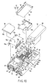
- a control circuit unit 56 As shown in FIG. 10, in the housing chamber 42 of the housing 34, a control circuit unit 56, two hard disk drive modules 57, CD-ROM drive 58, and power supply unit 59 are accommodated.
- the control circuit unit 56 is located at the bottom of the housing chamber 42.
- the control circuit unit 56 is equipped with a main circuit board 61 called a motherboard, three memories 62 mounted to the main circuit board 61, and first and second microprocessors 63a, 63b.
- the main circuit board 61 is screwed to the bottom plate 38 of the housing 34 and arranged horizontally along the bottom plate 38.
- the main circuit board 61 has a mount surface 61a on the opposite side of the bottom plate 38.
- the mount surface 61a faces the top plate 37 of the housing 34, and at the rear end of this mount surface 61a, the rear plate 40 is mounted.
- the memories 62 and the first and the second microprocessors 63a, 63b are circuit components for processing the data, and are located at the rear half of the housing chamber 42.
- each memory 62 has a long and narrow memory substrate 65 with a plurality of semiconductor packages 64 mounted.
- Each memory substrate 65 is mounted to the mount surface 61a of the main circuit board 61 via a socket 66.
- the memory substrates 65 extends to the depth direction of the housing 34 and are arranged parallel to the width direction of the housing 34 with intervals provided.
- the memory substrates 65 are tilted with respect to the main circuit board 61, with part overlapping over each other. By tilting the memory substrates 65 in this way, the overhang height of the memories 62 above the main circuit board 61 can be suppressed while securing the capacity of the memories 62.
- the first and the second microprocessors 63a, 63b as heat generating components are formed with, for example, PGA type semiconductor packages.
- the first and the second microprocessors 63a, 63b are supported by sockets 67 fixed to the mount surface 61a of the main circuit board 61, and are located next to the memories 62 on the left. These microprocessors 63a, 63b are removable from the sockets 67.
- the first and the second microprocessors 63a, 63b generate an extremely large volume of heat during operation in order to process a large volume of data at high speed, and require cooling for maintaining a stable action. Consequently, heat sinks 68 for promoting radiation are mounted to the top of the first and the second microprocessors 63a, 63b, respectively. The heat sinks 68 are thermally connected to the first and the second microprocessors 63a, 63b.
- the duct 71 has a pair of rising plates 72a, 72b and a top plate 73.
- the rising plates 72a, 72b rise from the mount surface 61a of the main circuit board 61, and face each other with the first and the second microprocessors 63a, 63b and heat sinks 68 in-between.
- the top plate 73 is arranged horizontally across the top end sections of the rising plates 72a, 72b, and faces the main circuit board 61.
- the rising plates 72a, 72b and top plate 73 form a cooling air passage 74 above the mount surface 61a of the main circuit board 61.
- the cooling air passage 74 is independent from the space inside the housing 34 and is open to the front and the rear of the housing chamber 42 in the inside of this housing 34.
- the rear end that corresponds to the downstream end of the cooling air passage 74 is continuous with the vent holes 41a, 41b of the housing 34.
- the first and the second microprocessors 63a, 63b and the heat sinks 68 are located inside the cooling air passage 74.
- a pair of cooling fans 75 are installed to the rear end section of the housing chamber 42 as a air feeding means.
- the cooling fans 75 are supported to the rear plate 40 of the housing 34, and are interposed between the duct 71 and the vent holes 41a, 41b.
- the cooling fans 75 are arranged side by side in the width direction of the housing 34 at the downstream end of the cooling air passage 74.
- cooling fans 75 When the cooling fans 75 are driven, air is sucked from the loading gate 43 at the front end of the housing 34 to the housing chamber 42. The majority of this air is guided to the cooling air passage 74 as cooling air. This cooling air is discharged to the outside of the housing 34 through vent holes 41a, 41b after it flows from the front to the rear in the cooling air passage 74.
- the first and the second microprocessors 63a, 63b are arranged displaced each other along the cooling air flowing direction in the cooling air passage 74. Consequently, the first microprocessor 63a is located upstream of the cooling air passage 74 from the second microprocessor 63b. Furthermore, the first and the second microprocessors 63a, 63b are arranged displaced each other along the direction crossing at right angles with the cooling air flowing direction, in other words, along the width direction of the housing 34, and are located at the front of the cooling fans 75, respectively.
- the first and the second microprocessors 63a, 63b are arranged with such positional relation maintained that their adjoining end sections face each other along the depth direction of the housing 34. Consequently, when the first and the second microprocessors 63a, 63b are observed from the upstream side along the cooling air flowing direction, these microprocessors 63a, 63b slightly overlap each other by the size X along the width direction of the housing 34.
- a frame 77 is arranged at the left end section of the front half of the housing chamber 42.
- the frame 77 is arranged for holding two hard disk modules 57 to the housing chamber 42.
- the frame 77 has a horizontal top plate 78 and a pair of guide plates 79a, 79b.
- the guide plates 79a, 79b extend downwards from the right and left side edge sections of the top plate 78, and the lower end sections of these guide plates 79a, 79b are screwed to the mount surface 61a of the main circuit board 61.
- the front end of this frame 77 faces on the loading gate 43 of the housing 34.
- a relay substrate 83 is arranged at the rear end opposite to the loading gate 43 of the frame 77.
- the relay substrate 83 is raised perpendicularly to face the loading gate 43.
- This relay substrate 83 is electrically connected to the main circuit board 61 via the connector (not illustrated) and has a pair of hard disk connectors 84 at the front surface that faces the loading gate 43.
- the hard disk drive module 57 comprises a hard disk drive (hereinafter called "HDD") 80 and a tray 82 that supports the HDD 80, and a lever 81 for loading-unloading operation.
- the tray 82 is horizontally inserted between guide plates 79a, 79b of the frame 77 from the loading gate 43, and the right and left side edge sections of this tray 82 are slidably supported to the guide plates 79a, 79b. Consequently, two hard disk drive modules 57 are held to the frame 77 as if they are stacked on top of another. In the condition where each hard disk drive module 57 is held to the frame 77, HDD 80 is connected to the hard disk connector 84 and the lever 81 faces the loading gate 43.
- HDD 80 is connected to the hard disk connector 84 and the lever 81 faces the loading gate 43.
- the top plate 78 of the frame 77 covers the hard disk drive module 57 from above.
- the top plate 78 has a plurality of support pieces 78a extending upwards to the outer peripheral section.
- the top plate 78 also has a function as a bracket that supports the CD-ROM drive 58, and the CD-ROM drive 58 is screwed to the support piece 78a of this top plate 78. Consequently, the CD-ROM drive 58 is housed in the housing chamber 42 as if it lies on top of the hard disk drive modules 57.
- the CD-ROM tray 58a of the CD-ROM drive 58 is exposed to outwards of the housing 34 through the opening section 47 of the front door 45 when the front door 45 is located at the first position.
- the power supply unit 59 is equipped with a metal case 86 that houses various kinds of circuit components that generate heat such as transformers and a cooling fan 87 for cooling the circuit components.
- the case 86 forms a narrow and long box extending in the depth direction of the housing 34, and is assembled into the right end section of the housing body 36 as if it covers the memories 62 from above.
- the case 86 of the power supply unit 59 is housed in the region generated on the right side of the duct 71 and is deviated from above the first and the second microprocessors 63a, 63b.
- the cooling fan 87 is located at the front end section of the case 86 and is housed on the right side of the hard disk drive modules 57.
- a communication card 88 for achieving wireless LAN is arranged below the cooling fan 87.
- the communication card 88 is exposed to the loading gate 43 of the housing 34, and as far as the front door 45 is located at the first position, the communication card 88 is covered with this front door 45.
- an extension card 90 for example, PCI type card
- the extension card 90 is held in the rear half of the housing chamber 42 via the card supporter 91.
- the card supporter 91 has a bracket 93 integrated with an extension support card 92.
- the bracket 93 is screwed to the housing body 36 and is housed in a clearance between the side plate 39a on the left side of the housing body 36 and the duct 71.
- the extension support card 92 is erected perpendicularly along the side plate 39a.
- the bottom end section of the extension support card 92 is electrically connected to the main circuit board 61.
- the top end section of the extension support card 92 overhung from the top plate 73 of the duct 71.
- an extension connector 94 is mounted to the top end section of the extension support card 92.
- the extension connector 94 extends horizontally along the depth direction of the housing 34 and to this extension connector 94, a terminal section 95 of the extension card 90 is removably inserted. Consequently, the extension card 90 is arranged horizontally along the top plate 73 of the duct 71.
- the extension card 90 has a side edge section 96 located on the side opposite to the terminal section 95. This side edge section 96 faces the case 86 of the power supply unit 59.
- This extension card 90 is supported by the top plate 73 of the duct 71 from below and by this, the positional relationship between the side edge section 96 of the extension card 90 and the case 86 is held constant. Consequently, interference between the circuit components (not illustrated) mounted to the extension card 90 and the case 86 is prevented.
- the cooling fans 75 are driven in accord with the operating condition of the server body 32.
- air is sucked into the housing chamber 42 through the vent holes 46 of the front door 45.
- This air reaches the cooling air passage 74 above the main circuit board 61 while passing through the hard disk drive modules 57. The majority of this air flows from front to rear through the cooling air passage 74 as cooling air.
- the cooling air comes in contact with the heat-generating first and the second microprocessors 63a, 63b as well as the heat sinks 68 thermally connected to these microprocessors 63a, 63b, and forcibly cools these microprocessors 63a, 63b and heat sinks 68.
- the cooling air heated by heat exchange between microprocessors 63a, 63b and heat sinks 68 is discharged to the rear of the housing 34 through vent holes 41a, 41b.
- the duct 71 forms the cooling air passage 74 independent from that inside the housing 34 on the mount surface 61a of the main circuit board 61, and by the existence of this duct 71, the cooling air flowing direction is guided. Consequently, the cooling air does not diffuse into the inside of the housing 34 and it is possible to concentratedly guide the cooling air to the first and the second microprocessors 63a, 63b.
- first and the second microprocessors 63a, 63b are displaced relative to the flowing direction of the cooling air as well as displaced one another in the direction crossing at right angles with that direction, these microprocessors 63a, 63b are not completely superimposed on each other along the cooling air flowing direction. Consequently, even though the second processor 63b is located in the cooling air flowing direction downstream of the first microprocessor 63a, the cooling air heated by the heat exchange with the first microprocessor 63a is not blown against the second microprocessor 63b and its heat sink 68.
- first and the second microprocessors 63a, 63b and heat sinks 68 are displaced one another, it is possible to expose the outer peripheral surfaces of these microprocessors 63a, 63b as well as the outer peripheral surfaces of the heat sinks 68 to the cooling air passage 74 throughout a wide range. Consequently, it is possible to successfully secure the contact area of the cooling air with microprocessors 63a, 63b as well as the cooling air with the heat sinks 68.
- first and the second microprocessors 63a, 63b slightly overlap in the width direction of the housing 34 as seen from the cooling air flowing direction, and it is possible to reduce the mounting area of the first and the second microprocessors 63a, 63b by the size X of this overlapping portion. Consequently, the main circuit board 61 can be formed in a reduced width, which is favorable for downsizing the housing 34.
- the power supply unit 59 that extends in the depth direction of the housing 34 is housed in the inside of the housing 34 at the position deviated to the left side of the first and the second microprocessors 63a, 63b.
- HDD is stacked in the housing height direction in the horizontal position, but the present invention shall not be limited to this, HDD may be raised perpendicularly to be arranged in the width direction of the housing.
- Heat generating components is not limited PGA type semiconductor package, but may be a circuit parts accompanying other heat generation. And the number of heat generating components shall not be limited to two but three or more.
Landscapes
- Engineering & Computer Science (AREA)
- Theoretical Computer Science (AREA)
- General Engineering & Computer Science (AREA)
- Physics & Mathematics (AREA)
- Human Computer Interaction (AREA)
- General Physics & Mathematics (AREA)
- Computer Hardware Design (AREA)
- Power Engineering (AREA)
- Thermal Sciences (AREA)
- Microelectronics & Electronic Packaging (AREA)
- Cooling Or The Like Of Electrical Apparatus (AREA)
- Cooling Or The Like Of Semiconductors Or Solid State Devices (AREA)
Abstract
Description
Claims (16)
- An information processing apparatus characterized by comprising:a duct (71) that forms a cooling air passage (74) through which cooling air flows; anda plurality of heat generating components (63a, 63b) which are cooled by the cooling air that flows the cooling air passage (74), said heat generating components (63a, 63b) being arranged displaced relative to the flowing direction of the cooling air as well as displaced one another in the direction crossing the cooling air flowing direction.
- The information processing apparatus according to claim 1, characterized by further comprising:a circuit board (61) equipped with a mount surface (61a), with the heat generating components (63a, 63b) being arranged and located on the mount surface (61a) of the circuit board (61).
- The information processing apparatus according to claim 2, characterized by further comprising:a plurality of heat sinks (68), these heat sinks (68) having laid on top of the heat generating components (63a, 63b), respectively, and having thermally connected to these heat generating components (63a, 63b).
- The information processing apparatus according to claim 3, characterized in thatthe duct (71) is installed on the mount surface (61a) of the circuit board (61) in the posture to cover the heat generating components (63a, 63b) and the heat sinks (68).
- The information processing apparatus according to claim 2, characterized in thatthe heat generating components (63a, 63b) have end sections which are adjacent to each other and the end sections of these heat generating components (63a, 63b) keep the positional relation to face each other as seen from the cooling air flowing direction.
- A information processing apparatus characterized by comprising:wherein the heat generating components (63a, 63b) are arranged displaced relative to the flowing direction of the cooling air as well as displaced one another in the direction crossing the cooling air flowing direction.a circuit board (61) housed in a housing (34) and equipped with a mount surface (61a);a plurality of heat generating components (63a, 63b) arranged and mounted on the mount surface (61a) of the circuit board (61);a duct (71) installed to the mount surface (61a) of the circuit board (61), said duct (71) having formed an independent cooling air passage (74) in the housing (34) inside and said heat generating components (63a, 63b) having been located in the cooling air passage (74); andan air feeding means (75) for feeding cooling air to the cooling air passage (74),
- The information processing apparatus according to claim 6, characterized by further comprising:heat sinks (68) individually and thermally connected to the heat generating components (63a, 63b), these heat sinks (68) having been interposed by the cooling air passage (74) and cooled by the cooling air.
- The information processing apparatus according to claim 6, characterized in thatthe air feeding means (75) has a plurality of cooling fans (75), and the cooling fans (75) are located at the downstream end of the cooling air passage (74) and discharge the cooling air heated by the heat generating components (63a, 63b) to the outside of the housing (34).
- The information processing apparatus according to claim 8, characterized in thatthe cooling fans (75) are arranged in such a manner to face the heat generating components (63a, 63b), respectively.
- The information processing apparatus according to claim 6, characterized in thatthe heat generating components (63a, 63b) have end sections that are adjacent to one another, and the end sections of these heat generating components (63a, 63b) keep the positional relationship to face each other as seen from the cooling air flowing direction.
- The information processing apparatus according to claim 6, characterized in thatthe duct (71) has a pair of rising plates (72a, 72b) facing each other with the heat generating components (63a, 63b) in-between as well as a top plate 73 being laid across the top end sections of the rising plates (72a, 72b), and these rising plates (72a, 72b) and the top plate (73) form the cooling air passage (74) in cooperation with the circuit board (61).
- The information processing apparatus according to claim 11, characterized in thatthe circuit board (61) supports an extension support card (92) arranged perpendicularly along one of the rising plates (72a) of the duct (71), the extension support card (92) has an connector (94) at the top end section overhung from the top plate (73) of the duct (71), to which an extension card (90) is removably connected, and the extension card (90) is arranged along the top plate (73) of the duct (71).
- The information processing apparatus according to claim 12, characterized in thatthe duct (71) is composed with electrical insulation material and supports the extension card (90) from below.
- The information processing apparatus according to claim 13, characterized in thatthe housing (34) has an area that accommodates a unit (59) equipped with a metal case (86) in its inside, the area is displaced from above the duct (71) and the case (86) of the unit (59) is aligned with the extension card (90) above the circuit board (61).
- An information processing apparatus characterized by comprising:a housing (34) equipped with a removable top plate (37);a circuit board (61) which is housed in the housing (34) and which has a mount surface (61a) that opposes to the top plate (37);a duct (71) that is removably housed in the housing (34) inside, said duct (71) having formed a cooling air passage (74) independently from the housing (34) inside on the mount surface (61a) of the circuit board (61);a plurality of heat generating components (63a, 63b) removably mounted on the mount surface (61a) of the circuit board (61) and cooled by cooling air that flows the cooling air passage (74), said heat generating components (63a, 63b) having been arranged displaced relative to the flowing direction of the cooling air as well as displaced one another in the direction crossing the cooling air flowing direction; anda power supply unit (59) housed inside the housing (34), said power supply unit (59) having been installed to the place deviated from the duct (71).
- The information processing apparatus according to claim 15, characterized in thatthe heat generating components (63a, 63b) are microprocessors, and the microprocessors are removably supported to sockets (67) fixed to the circuit board (61).
Applications Claiming Priority (2)
| Application Number | Priority Date | Filing Date | Title |
|---|---|---|---|
| JP2001082695 | 2001-03-22 | ||
| JP2001082695A JP3513116B2 (en) | 2001-03-22 | 2001-03-22 | Information processing equipment |
Publications (2)
| Publication Number | Publication Date |
|---|---|
| EP1244002A2 true EP1244002A2 (en) | 2002-09-25 |
| EP1244002A3 EP1244002A3 (en) | 2003-09-17 |
Family
ID=18938610
Family Applications (1)
| Application Number | Title | Priority Date | Filing Date |
|---|---|---|---|
| EP01122232A Withdrawn EP1244002A3 (en) | 2001-03-22 | 2001-09-17 | Information processing apparatus having cooling air passage with a plurality of heat generating components interposed |
Country Status (3)
| Country | Link |
|---|---|
| US (1) | US6525937B2 (en) |
| EP (1) | EP1244002A3 (en) |
| JP (1) | JP3513116B2 (en) |
Cited By (1)
| Publication number | Priority date | Publication date | Assignee | Title |
|---|---|---|---|---|
| CN103946767A (en) * | 2011-11-18 | 2014-07-23 | 萨基姆宽带联合股份公司 | Electronic devices such as modems that include multiple air-cooled processors |
Families Citing this family (53)
| Publication number | Priority date | Publication date | Assignee | Title |
|---|---|---|---|---|
| US7088581B2 (en) * | 2002-07-23 | 2006-08-08 | Silicon Graphics, Inc. | External fan and method for exchanging air with modular bricks in a computer system |
| JP4896359B2 (en) * | 2003-01-28 | 2012-03-14 | 富士通株式会社 | Electronic equipment |
| JP4263493B2 (en) * | 2003-01-28 | 2009-05-13 | 富士通株式会社 | Casing, device unit and fan unit |
| JP4199018B2 (en) * | 2003-02-14 | 2008-12-17 | 株式会社日立製作所 | Rack mount server system |
| JP3688685B2 (en) | 2003-02-28 | 2005-08-31 | 株式会社東芝 | Electronics |
| JP2004265999A (en) | 2003-02-28 | 2004-09-24 | Toshiba Corp | Electronics |
| TWM244718U (en) * | 2003-08-22 | 2004-09-21 | Hon Hai Prec Ind Co Ltd | Heat dissipating device employing air duct |
| US6987673B1 (en) * | 2003-09-09 | 2006-01-17 | Emc Corporation | Techniques for cooling a set of circuit boards within a rack mount cabinet |
| US20050207098A1 (en) * | 2004-03-16 | 2005-09-22 | Malone Christopher G | Electrical equipment housings having a horizontally mounted connection plane |
| US7408775B2 (en) * | 2004-10-19 | 2008-08-05 | Honeywell International Inc. | Electrical module and support therefor with integrated cooling |
| US20060215366A1 (en) * | 2005-03-24 | 2006-09-28 | Vinod Kamath | Apparatus, system, and method for removing excess heat from a component |
| US7319596B2 (en) * | 2006-03-24 | 2008-01-15 | Fujitsu Limited | Electronic apparatus |
| US7365977B2 (en) * | 2006-03-24 | 2008-04-29 | Fujitsu Limited | Electronic apparatus |
| US7289323B2 (en) * | 2006-03-29 | 2007-10-30 | Inventec Corporation | Wind-guiding cover |
| JP4745206B2 (en) * | 2006-11-30 | 2011-08-10 | 株式会社東芝 | Electronics |
| JP2008187136A (en) * | 2007-01-31 | 2008-08-14 | Densei Lambda Kk | Heat dissipating structure |
| US7660111B2 (en) | 2007-11-29 | 2010-02-09 | International Business Machines Corporation | Removable cooling duct with interlocking dovetail connections for an air tight thermal seal |
| JP4930429B2 (en) * | 2008-03-28 | 2012-05-16 | 富士通株式会社 | Device for cooling the printed circuit board |
| US7843685B2 (en) * | 2008-04-22 | 2010-11-30 | International Business Machines Corporation | Duct system for high power adapter cards |
| US20090289532A1 (en) * | 2008-05-22 | 2009-11-26 | Accusys. Inc. | Modular structure of storage device |
| US9426903B1 (en) | 2008-06-27 | 2016-08-23 | Amazon Technologies, Inc. | Cooling air stack for computer equipment |
| US8009417B2 (en) * | 2009-08-28 | 2011-08-30 | Hewlett-Packard Development Company, L.P. | Removable airflow guide assembly for a computer system |
| CN201562214U (en) * | 2009-10-14 | 2010-08-25 | 鸿富锦精密工业(深圳)有限公司 | Electronic device shell |
| JP5003772B2 (en) * | 2010-02-10 | 2012-08-15 | 富士通株式会社 | Air duct and electronic device |
| US8755192B1 (en) | 2010-03-31 | 2014-06-17 | Amazon Technologies, Inc. | Rack-mounted computer system with shock-absorbing chassis |
| US9894808B2 (en) | 2010-03-31 | 2018-02-13 | Amazon Technologies, Inc. | Compressed air cooling system for data center |
| US9622387B1 (en) | 2010-03-31 | 2017-04-11 | Amazon Technologies, Inc. | Rack-mounted air directing device with scoop |
| US8526177B2 (en) * | 2010-05-04 | 2013-09-03 | Hewlett-Packard Development Company, L.P. | Fan for cooling multiple processors housed in a sub-chassis |
| US10492331B1 (en) | 2010-09-29 | 2019-11-26 | Amazon Technologies, Inc. | System and method for cooling power distribution units |
| US8295050B2 (en) * | 2010-11-05 | 2012-10-23 | Portwell Inc. | Dual CPU and heat dissipating structure thereof |
| CN102486673A (en) * | 2010-12-06 | 2012-06-06 | 鸿富锦精密工业(深圳)有限公司 | Computer case cooling system |
| CN102654790A (en) * | 2011-03-03 | 2012-09-05 | 鸿富锦精密工业(深圳)有限公司 | Heat radiation system |
| US9075581B2 (en) * | 2011-04-19 | 2015-07-07 | Germane Systems, Llc | Apparatus and method for cooling electrical components of a computer |
| US9095070B2 (en) | 2011-12-05 | 2015-07-28 | Amazon Technologies, Inc. | Partial-width rack-mounted computing devices |
| US8773861B2 (en) | 2011-12-15 | 2014-07-08 | Amazon Technologies, Inc. | Reconfigurable shelf for computing modules |
| US8720043B2 (en) | 2011-12-15 | 2014-05-13 | Amazon Technologies, Inc. | Method of allocating resources in a rack system |
| US8867214B2 (en) | 2011-12-15 | 2014-10-21 | Amazon Technologies, Inc. | Modular server design for use in reconfigurable server shelf |
| CN103379794A (en) * | 2012-04-13 | 2013-10-30 | 鸿富锦精密工业(深圳)有限公司 | Electronic apparatus |
| JP5678926B2 (en) * | 2012-07-12 | 2015-03-04 | 日本電気株式会社 | Server enclosure, server module, server system |
| US10082857B1 (en) | 2012-08-07 | 2018-09-25 | Amazon Technologies, Inc. | Cooling electrical systems based on power measurements |
| US9894809B1 (en) | 2013-02-28 | 2018-02-13 | Amazon Technologies, Inc. | System for supplying cooling air from sub-floor space |
| TW201443383A (en) * | 2013-05-08 | 2014-11-16 | Hon Hai Prec Ind Co Ltd | Air duct |
| US9788451B2 (en) * | 2013-12-23 | 2017-10-10 | Dell Products, L.P. | Block chassis sled having one-third width computing and storage nodes for increased processing and storage configuration flexibility within a modular, scalable and/or expandable rack-based information handling system |
| US9417671B2 (en) * | 2014-03-29 | 2016-08-16 | Lenovo (Singapore) Pte. Ltd. | Computer baffle |
| US9961806B2 (en) * | 2016-05-19 | 2018-05-01 | Power Distribution Systems Development LLC | Systems and methods for transformer cooling by vertical airflow |
| KR102257074B1 (en) * | 2016-12-26 | 2021-05-27 | 미쓰비시덴키 가부시키가이샤 | Filter device and power conversion device |
| DE102017104007A1 (en) * | 2017-02-27 | 2018-08-30 | Krohne Messtechnik Gmbh | Device for receiving electronics |
| US10008245B1 (en) * | 2017-06-30 | 2018-06-26 | Microsoft Technology Licensing, Llc | Positioning components in a rack to permit base plane access |
| JP6508281B2 (en) * | 2017-10-04 | 2019-05-08 | 三菱電機株式会社 | Filter device and power converter |
| FR3073119A1 (en) * | 2017-10-31 | 2019-05-03 | Airbus Operations | ASSEMBLY COMPRISING A CARRIER STRUCTURE COMPRISING VERTICAL STRUCTURAL ELEMENTS AND A MODULE COMPRISING ELECTRONIC EQUIPMENT FIXED ON THE FRONT PANEL OF THE VERTICAL STRUCTURAL ELEMENTS |
| US12010810B2 (en) * | 2020-12-29 | 2024-06-11 | Legrand DPC, LLC | Extendable cable enclosure |
| US20250338451A1 (en) * | 2024-04-25 | 2025-10-30 | Dell Products L.P. | Computer system cooling using ventilation channel device |
| TWI916158B (en) | 2025-01-13 | 2026-02-21 | 緯創資通股份有限公司 | Air baffle and electronic device including air baffle |
Family Cites Families (13)
| Publication number | Priority date | Publication date | Assignee | Title |
|---|---|---|---|---|
| US5294831A (en) * | 1991-12-16 | 1994-03-15 | At&T Bell Laboratories | Circuit pack layout with improved dissipation of heat produced by high power electronic components |
| JPH0824222B2 (en) * | 1992-04-10 | 1996-03-06 | インターナショナル・ビジネス・マシーンズ・コーポレイション | Cooling device with air-mixer cooling plate |
| US5285350A (en) * | 1992-08-28 | 1994-02-08 | Aavid Engineering, Inc. | Heat sink plate for multiple semi-conductors |
| US5446619A (en) * | 1993-08-12 | 1995-08-29 | Compaq Computer Corp. | Card extender unit for computer |
| TW265430B (en) * | 1994-06-30 | 1995-12-11 | Intel Corp | Ducted opposing bonded fin heat sink blower multi-microprocessor cooling system |
| US5734551A (en) * | 1995-11-07 | 1998-03-31 | Sun Microsystems, Inc. | Method to install SIMMs without causing discomfort to the user |
| US5691883A (en) * | 1995-12-27 | 1997-11-25 | Intel Corporation | Multiple intake duct microprocessor cooling system |
| JPH09223883A (en) * | 1996-02-16 | 1997-08-26 | Hitachi Ltd | Electronic equipment cooling device |
| EP0893042A1 (en) * | 1996-04-10 | 1999-01-27 | Intergraph Corporation | Removable circuit board with ducted cooling |
| US5949645A (en) * | 1997-06-02 | 1999-09-07 | Northern Telecom Limited | Electronic unit |
| US6198628B1 (en) * | 1998-11-24 | 2001-03-06 | Unisys Corporation | Parallel cooling of high power devices in a serially cooled evironment |
| JP3721277B2 (en) | 1999-02-12 | 2005-11-30 | 株式会社Pfu | Electronic equipment cooling structure |
| US6359781B1 (en) * | 2000-04-21 | 2002-03-19 | Dell Products L.P. | Apparatus for cooling heat generating devices |
-
2001
- 2001-03-22 JP JP2001082695A patent/JP3513116B2/en not_active Expired - Fee Related
- 2001-09-17 EP EP01122232A patent/EP1244002A3/en not_active Withdrawn
- 2001-09-19 US US09/955,070 patent/US6525937B2/en not_active Expired - Fee Related
Cited By (2)
| Publication number | Priority date | Publication date | Assignee | Title |
|---|---|---|---|---|
| CN103946767A (en) * | 2011-11-18 | 2014-07-23 | 萨基姆宽带联合股份公司 | Electronic devices such as modems that include multiple air-cooled processors |
| CN103946767B (en) * | 2011-11-18 | 2018-12-14 | 萨基姆宽带联合股份公司 | Electronic devices such as modems that include multiple air-cooled processors |
Also Published As
| Publication number | Publication date |
|---|---|
| JP2002280778A (en) | 2002-09-27 |
| JP3513116B2 (en) | 2004-03-31 |
| US6525937B2 (en) | 2003-02-25 |
| EP1244002A3 (en) | 2003-09-17 |
| US20020134531A1 (en) | 2002-09-26 |
Similar Documents
| Publication | Publication Date | Title |
|---|---|---|
| US6525937B2 (en) | Information processing apparatus having cooling air passage with a plurality of heat generating components interposed | |
| US7286345B2 (en) | Rack-mounted air deflector | |
| JP4747161B2 (en) | Method and apparatus for mounting computer components | |
| US7352571B2 (en) | Disk array device | |
| US7061761B2 (en) | System and method for cooling components in an electronic device | |
| JP5043037B2 (en) | Airflow management system for electronic equipment chassis | |
| US6621693B1 (en) | Low profile, high density storage array | |
| US7561428B2 (en) | Information processing apparatus | |
| US6958906B2 (en) | Method and apparatus for cooling a modular computer system with dual path airflow | |
| US20080151497A1 (en) | Server cabinet with air exhaust apparatus | |
| US8714666B2 (en) | Casing, module substrate, and air-cooling system | |
| US8451606B2 (en) | Electronic device | |
| US7133288B2 (en) | Processor heat sink retention module and assembly | |
| USRE40630E1 (en) | Low profile computer case and computer | |
| JP2002032153A (en) | Cartridge type server unit and housing for mounting the server unit | |
| JP2004240967A (en) | Blade server | |
| US20250168963A1 (en) | Heatsink techniques for optical and electrical modules | |
| JP4714308B2 (en) | Electronics | |
| JPH0246965B2 (en) | ||
| US4985803A (en) | Housing for a multi-board electronic module for a programmable controller system | |
| US20070082598A1 (en) | Module frame for receiving electronic plug-in modules | |
| KR20190041964A (en) | Electronics | |
| JP2002278652A (en) | Information processing device | |
| JP2005108969A (en) | Fan unit mounting structure | |
| JP2018189264A (en) | Air conditioner outdoor unit |
Legal Events
| Date | Code | Title | Description |
|---|---|---|---|
| PUAI | Public reference made under article 153(3) epc to a published international application that has entered the european phase |
Free format text: ORIGINAL CODE: 0009012 |
|
| 17P | Request for examination filed |
Effective date: 20010917 |
|
| AK | Designated contracting states |
Kind code of ref document: A2 Designated state(s): AT BE CH CY DE DK ES FI FR GB GR IE IT LI LU MC NL PT SE TR |
|
| AX | Request for extension of the european patent |
Free format text: AL;LT;LV;MK;RO;SI |
|
| PUAL | Search report despatched |
Free format text: ORIGINAL CODE: 0009013 |
|
| AK | Designated contracting states |
Kind code of ref document: A3 Designated state(s): AT BE CH CY DE DK ES FI FR GB GR IE IT LI LU MC NL PT SE TR |
|
| AX | Request for extension of the european patent |
Extension state: AL LT LV MK RO SI |
|
| 17Q | First examination report despatched |
Effective date: 20040123 |
|
| AKX | Designation fees paid |
Designated state(s): DE FR GB |
|
| STAA | Information on the status of an ep patent application or granted ep patent |
Free format text: STATUS: THE APPLICATION IS DEEMED TO BE WITHDRAWN |
|
| 18D | Application deemed to be withdrawn |
Effective date: 20050330 |