EP1243964A2 - Reflective plate, liquid crystal display (LCD) using same, and electronic apparatus using this LCD - Google Patents
Reflective plate, liquid crystal display (LCD) using same, and electronic apparatus using this LCD Download PDFInfo
- Publication number
- EP1243964A2 EP1243964A2 EP02251751A EP02251751A EP1243964A2 EP 1243964 A2 EP1243964 A2 EP 1243964A2 EP 02251751 A EP02251751 A EP 02251751A EP 02251751 A EP02251751 A EP 02251751A EP 1243964 A2 EP1243964 A2 EP 1243964A2
- Authority
- EP
- European Patent Office
- Prior art keywords
- reflective
- light
- subregions
- reflected
- exit region
- Prior art date
- Legal status (The legal status is an assumption and is not a legal conclusion. Google has not performed a legal analysis and makes no representation as to the accuracy of the status listed.)
- Withdrawn
Links
Images






Classifications
-
- G—PHYSICS
- G02—OPTICS
- G02B—OPTICAL ELEMENTS, SYSTEMS OR APPARATUS
- G02B5/00—Optical elements other than lenses
- G02B5/08—Mirrors
-
- G—PHYSICS
- G02—OPTICS
- G02F—OPTICAL DEVICES OR ARRANGEMENTS FOR THE CONTROL OF LIGHT BY MODIFICATION OF THE OPTICAL PROPERTIES OF THE MEDIA OF THE ELEMENTS INVOLVED THEREIN; NON-LINEAR OPTICS; FREQUENCY-CHANGING OF LIGHT; OPTICAL LOGIC ELEMENTS; OPTICAL ANALOGUE/DIGITAL CONVERTERS
- G02F1/00—Devices or arrangements for the control of the intensity, colour, phase, polarisation or direction of light arriving from an independent light source, e.g. switching, gating or modulating; Non-linear optics
- G02F1/01—Devices or arrangements for the control of the intensity, colour, phase, polarisation or direction of light arriving from an independent light source, e.g. switching, gating or modulating; Non-linear optics for the control of the intensity, phase, polarisation or colour
- G02F1/13—Devices or arrangements for the control of the intensity, colour, phase, polarisation or direction of light arriving from an independent light source, e.g. switching, gating or modulating; Non-linear optics for the control of the intensity, phase, polarisation or colour based on liquid crystals, e.g. single liquid crystal display cells
- G02F1/133—Constructional arrangements; Operation of liquid crystal cells; Circuit arrangements
- G02F1/1333—Constructional arrangements; Manufacturing methods
- G02F1/1335—Structural association of cells with optical devices, e.g. polarisers or reflectors
-
- G—PHYSICS
- G02—OPTICS
- G02F—OPTICAL DEVICES OR ARRANGEMENTS FOR THE CONTROL OF LIGHT BY MODIFICATION OF THE OPTICAL PROPERTIES OF THE MEDIA OF THE ELEMENTS INVOLVED THEREIN; NON-LINEAR OPTICS; FREQUENCY-CHANGING OF LIGHT; OPTICAL LOGIC ELEMENTS; OPTICAL ANALOGUE/DIGITAL CONVERTERS
- G02F1/00—Devices or arrangements for the control of the intensity, colour, phase, polarisation or direction of light arriving from an independent light source, e.g. switching, gating or modulating; Non-linear optics
- G02F1/01—Devices or arrangements for the control of the intensity, colour, phase, polarisation or direction of light arriving from an independent light source, e.g. switching, gating or modulating; Non-linear optics for the control of the intensity, phase, polarisation or colour
- G02F1/13—Devices or arrangements for the control of the intensity, colour, phase, polarisation or direction of light arriving from an independent light source, e.g. switching, gating or modulating; Non-linear optics for the control of the intensity, phase, polarisation or colour based on liquid crystals, e.g. single liquid crystal display cells
- G02F1/133—Constructional arrangements; Operation of liquid crystal cells; Circuit arrangements
- G02F1/1333—Constructional arrangements; Manufacturing methods
- G02F1/1335—Structural association of cells with optical devices, e.g. polarisers or reflectors
- G02F1/133553—Reflecting elements
Definitions
- the present invention relates to a reflective plate used in a reflective type display.
- the invention also relates to a liquid crystal display (LCD) using such a reflective plate.
- the invention relates to electronic apparatus using such a liquid crystal display.
- liquid crystal displays have been applied to personal computers (PCs), TV receivers, wordprocessors, video taperecorders, and so on. Meanwhile, such electronic apparatus have been required to have more functions. Also, there is a demand for miniaturization, power saving, and lower costs. For these purposes, there is a demand for a reflective type liquid crystal display that displays a liquid crystal image by reflecting externally incident light without using backlight.
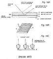
- a reflective film 4 used in a reflective type liquid crystal display is placed below a liquid-crystal layer 38 and reflects incident ambient light. A part of the ambient light is reflected by the surface of an upper substrate 2; the remaining ambient light passes through the upper substrate 2 and the liquid-crystal layer 38 and is reflected by the reflective film 4. Therefore, if the direction of reflection of light at the surface of the upper substrate 2 is identical with the direction of reflection of light at the reflective film 4, the light source is seen to overlap the image on the liquid crystal display. This presents the problem that the image is not viewed comfortably, i.e., the visibility is deteriorated.
- the irregularities 3 reflect incident light, Where light incident on the reflective film 4 is reflected by the irregularities 3, the LCD screen can be visually observed using light not directed in the same direction as those components of the scattered light which are regularly reflected at the upper substrate 2. It is possible to observe the LCD screen from a direction different from the light regularly reflected off the upper substrate 2. This improves the visibility.
- the angle of reflection ⁇ can be adjusted by appropriately selecting the tilt angle at the surface of convex portion 3a.
- the light not directed in the same direction as the light regularly reflected from the surface of the upper substrate 2 can be guided to the view position.
- each irregularity 3 is made to have a minute area, and if light incident normal to the reflective film 4 spreads within angle ⁇ , the light reflected by the reflective film 4 is reflected to regions II, III, and IV (Fig. 17A) excluding both-side regions I that light reflected from the reflective film 4 does not reach at all.
- regions III With respect to the regions III, light reflected from the left side ⁇ L and the right side ⁇ R of the reflective plate 1 reaches these regions III. Since these regions are not affected by regular reflection from the upper substrate 2, the image on the LCD screen can be recognized.
- the regions III are used as an effective field of view area that is a viewable LCD screen.
- a reflective plate which can be used in a reflective LCD screen and form reflected light-exiting regions in the effective field of view areas obliquely above or below the reflective plate.
- a reflective plate according to the present invention has a plurality of reflective subregions each of which has at least one reflective surface for reflecting light. The light reflected from these reflective subregions form spreads of exit. These spreads of exit intersect each other at a given upper position to thereby form a common exit region.
- This reflective plate is characterized in that the reflective subregions are so arranged that light rays incident on the reflective plate from a vertical direction are reflected substantially toward the center of the exit region located outside a region lying vertically above the reflective plate, and that the centers of intensities of the reflected light rays concentrate at the center of the exit region.
- the reflective subregions (or reflective unit regions) referred to herein are partitioned from each other by concave or convex portions and are regions that reflect incident light.
- Each reflective subregion may be one of reflective sections partitioned from each other by concave or convex portions or an assemblage of such reflective sections. If each reflective subregion is partitioned from other subregions by concave portions, the inside is inevitably convex.
- This convex portion is a flat plane tilted to one side and having a uniform angle of reflection, a convex spherical plane, or convex aspherical plane. If each reflective subregion is partitioned from other subregions by convex portions, the inside is inevitably concave.
- This concave portion is a flat plane tilted to one side and having a uniform angle of reflection, a concave spherical plane, or concave aspherical plane.
- the reflective surface of the interior partitioned from others by the concave or convex portions is not limited to a flat plane having a uniform angle of reflection.
- the height of the plane increases or decreases monotonously.
- a minute convex or concave portion may be formed at an intermediate height of the plane.
- the aforementioned concave or convex spherical plane or aspherical plane may vary continuously in curvature.
- a minute convex or concave portion may be formed in its intermediate position.
- That "are reflected substantially toward the center of the exit region" means that this reflective plate is applied to a liquid crystal display and that a person who observes this liquid crystal display is in a viewable range with a tolerable viewable range of about ⁇ 30°.
- That " light rays concentrate at the center of the exit region” means that "it is desirable that the light rays are concentrated at one point but slight variations are permissible. For example, where the center of an ideal exit region is taken as a virtual center, the same effect is produced if the center of intensity of reflected light is within the angular spread of about ⁇ 30° described above about the virtual center, and the light rays are concentrated at the center of the exit region.”
- a reflective plate has plural reflective subregions each having at least one reflective surface that reflects light.
- Light reflected from the reflective subregions form spreads of exit which intersect each other at a given upper position and together form a common exit region. Therefore, the reflected light can be guided and concentrated to the given upper position.
- Light incident on the reflective plate from a vertical direction is reflected by the reflective subregions substantially toward the center of the exit region lying outside a region that is located vertically above the reflective plate.
- the reflective subregions are so arranged that the centers of the reflected light rays concentrate at the center of the exit region. Therefore, where this reflective plate is applied to a liquid crystal display, a brighter liquid crystal display can be observed at the common exit region owing to the concentrated light rays.
- the shape of the reflective surface is preferably made different according to the installation position. This technical means makes it possible to set the direction of the reflective surface at will. Reflected light can be concentrated in a desired direction.
- the reflective subregions are so arranged that the angle formed between the light incident on the reflective subregions and the reflected light arising from the incident light decreases in going toward the center of the exit region.
- this technical means by reducing the angle formed between the light incident on each reflective subregion and the reflected light arising from the incident light as the reflective subregion comes closer to the center of the common exit region, the center of intensity of the exit region can be concentrated at the exit region. Consequently, the common exit region can be made brighter.
- the surfaces of the reflective subregions that face the exit region preferably have plural curved surfaces. This technical means permits one to set the direction of reflective surfaces at will. This can prevent variations in brightness as viewed from the direction of reflection. Hence, the directivity can be enhanced. At the same time, brightness variations can be reduced.
- the aforementioned plural reflective subregions are preferably arranged coaxially from the point (hereinafter referred to as the projection point) obtained by projecting the center of the exit region onto a plane including the reflective plate.
- Normal lines to the tilted surfaces of the reflective subregions are preferably tilted toward the projection point.
- the normal lines preferably have the same tilt angle on the same coaxial circle.
- the "plane including the reflective plate” means a virtual plane extending outward from the end of the reflective plate.
- the plane may be a virtual plane extending from a reflective film forming the reflective plate. Also, the virtual plane may extend from that position vertically beyond the cross-sectional thickness of the reflective plate.
- the reflective subregions arranged coaxially from the projection point of the center of the exit regions are so disposed that their reflective surfaces having the same tilt angle are directed toward the projection point. Therefore, the centers of intensities of their respective exit regions can be concentrated at the center of the exit region. In consequence, the common exit region can be made brighter.
- the center of the exit region is preferably present within a virtual plane extending normal to the surface of the reflective plate on a substantially bisector line of the reflective plate. Because of this technical means, the centers of intensities of their respective exit regions concentrated at the center of the exit region are placed at the substantially bisector line of the reflective plate and so when this is applied to a liquid crystal display, symmetrical right and left positions can be displayed brightly.
- a liquid crystal display has first and second substrates disposed opposite to each other, a liquid-crystal layer consisting of a liquid crystal sealed in between the first and second substrates, and a reflective layer having a plurality of reflective subregions each of which has at least one reflective surface formed on the second substrate for reflecting light.
- the liquid crystal display has the following features. First incident light incident from a given direction on the surface of the first substrate that faces away from the liquid-crystal layer is divided into at least first reflected light and second incident light. The first reflected light is produced by regular reflection at the surface of the first substrate. The second incident light reaches the reflective subregions via the first substrate and liquid-crystal layer.
- the second incident light is reflected from the reflective subregions, forming second reflected light which forms plural spreads of exit. These spreads of exit intersect each other at a given position above the first substrate, thus forming a common exit region.
- the second reflected light is reflected substantially toward the center of the exit region.
- the centers of intensities of reflected light rays concentrate at the center of the exit region.
- the reflective subregions are so arranged that the center of the exit region is formed in a given position not in the direction of travel of the first reflected light.
- plural spreads of exit formed by the second reflected light reflected from the reflective subregions intersect each other at the given position above the first substrate and form the common exit region.
- the second reflected light is reflected substantially toward the center of the exit region.
- the centers of the intensities of the reflected light rays concentrate at the center of the exit region. Because of this first feature, the centers of intensities of their respective exit regions can be concentrated at the center of the exit region. Consequently, the common exit region can be made brighter.
- the reflective subregions are so arranged that the center of the exit region is formed in a given position not in the direction of travel of the first reflected light.
- This first reflected light is created as the first incident light incident on the surface of the first substrate facing away from the liquid-crystal layer from a given direction and is reflected regularly from the surface of the first substrate. Because of this feature, the first reflected light and the second reflected light forming the exit region are not emitted in the same direction. Therefore, the image owing to the liquid crystal display is not superimposed on the first reflected light when viewed by a person. Consequently, the liquid crystal display can be viewed well.
- the center of the exit region is preferably present within a virtual plane extending normal to the surface of the second substrate on the substantially bisector line of the second substrate. Because of this technical means, the centers of intensities of their respective exit regions concentrated at the center of the exit region are placed on the substantially bisector line of the LCD screen. Therefore, symmetrical right and left positions on the screen can be displayed brightly.
- Electronic apparatus is equipped with a liquid crystal display having a reflective plate.
- This apparatus has a display portion including the liquid crystal display comprising first and second substrates disposed opposite to each other, a liquid-crystal layer consisting of a liquid crystal sealed in between the first and second substrates, and a reflective layer formed on the second substrate.
- the reflective layer has plural reflective subregions each having at least one reflective surface for reflecting light.
- the liquid crystal display has the following features. First incident light incident from a given direction on the surface of the first substrate that faces away from liquid-crystal layer is divided into at least first reflected light and second incident light. The first reflected light is produced by regular reflection at the surface of the first substrate.
- the second incident light reaches the reflective subregions via the first substrate and liquid-crystal layer.
- the second incident light is reflected from the reflective subregions, forming second reflected light which forms plural spreads of exit. These spreads of exit intersect each other at a given position above the first substrate, thus forming a common exit region.
- the second reflected light is reflected substantially toward the center of the exit region.
- the centers of intensities of the reflected light rays concentrate at the center of the exit region.
- the reflective subregions are so arranged that the center of the exit region is formed in a given position not in the direction of travel of the first reflected light.
- the present invention is characterized in that the display portion of the electronic apparatus is constructed from the liquid crystal display described above. Therefore, in the display portion, plural spreads of exit formed by the second reflected light reflected from the reflective subregions intersect each other at the given position above the first substrate and form a common exit region.
- the second reflected light is reflected substantially toward the center of the exit region.
- the centers of the intensities of the reflected light rays concentrate at the center of the exit region. Because of this first feature, the centers of intensities of their respective exit regions can be concentrated at the center of the exit region. In consequence, the common exit region can be made brighter.
- the reflective subregions are so arranged that the center of the exit region is formed in a given position not in the direction of travel of the first reflected light.
- This first reflected light is created as the first incident light incident on the surface of the first substrate facing away from the liquid-crystal layer from a given direction and is reflected regularly from the surface of the first substrate. Because of this feature, the first reflected light and the second reflected light forming the exit region are not emitted in the same direction. Therefore, the image owing to the liquid crystal display is not superimposed on the first reflected light when viewed by a person. Consequently, the liquid crystal display can be viewed well.
- a method of reflecting light by a reflective plate in accordance with the present invention is implemented with the reflective plate having plural reflective subregions each having at least one reflective surface for reflecting light. Light reflected from the reflective subregions form plural spreads of exit which intersect each other at a given upper position to thereby form a common exit region.
- This method is characterized as follows. The light is made to enter the reflective plate from a vertical direction. The incident light is reflected by the plural reflective subregions. The light rays reflected by the reflective subregions are directed substantially toward the center of the exit region located outside a region located vertically above the reflective plate. The centers of intensities of the reflected light rays are concentrated at the center of the exit region. Where this method of reflecting light is applied to a liquid crystal display, the liquid crystal display can be observed brightly in the common region by the concentrated light rays.
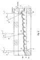
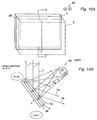
- Fig. 1 is a cross-sectional view illustrating main portions of a reflective plate according to an embodiment of the present invention.
- Fig. 2 is a view illustrating an enlarged cross-sectional shape of the reflective film of Fig. 1.
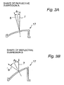
- Fig. 3 is a cross-sectional view illustrating plane geometries of convex portions on reflective films.
- Fig. 4 is a plan view of a reflective plate according to a first embodiment.
- a reflective liquid crystal display 10 composed of an upper substrate 2, a liquid-crystal layer 38, and a reflective plate 1 is shown in cross section,
- the reflective plate 1 consists of an opaque or transparent lower substrate 11, together with a resinous layer 6 and a reflective film 4 formed on the lower plate 11.
- the lower plate is made of ceramic, glass, plastic, or the like.
- Fig. 1 is a schematic view and is not drawn, taking account of the differences between the refractive indices of various layers such as the liquid-crystal layer 38 and the upper substrate 2.
- the reflective film 4 is shown to be planar. However, convex portions 17 having reflective tilted surfaces (described later) are formed on its upper surface 4a.
- Incident light 7 entering through the upper substrate 2 is partially reflected by the surface 2a of the upper substrate 2 and returns.
- the light entering the upper substrate 2 reaches reflective subregions 13 which are so arranged that the angle ⁇ between the incident light and the reflected light varies in going from region A to region B.
- the incident light 7 reflects at an angle of ⁇ 1 .
- the incident light 7 reflects at an angle of ⁇ 3 .
- Reflected light 8 forms a substantially circular exit region 14 spreading as reflected light rays 8a and 8b within an angular range of ⁇ .
- reflected light 9 forms the substantially circular exit region 14 spreading as reflected light rays 9a and 9b within an angular range of ⁇ .
- the center 12 of this exit region 14 is formed on a normal line at a distance of M from the end of the reflective liquid crystal display 10. With respect to the position of this center 12, where the horizontal length L of the reflective liquid crystal display 10 as viewed on Fig.
- the shape of the convex portions 17 on the reflective film 4 is so set that the angle ⁇ between the incident light and the reflected light 8, 15, or 9 increases in going from the region A to the region B.
- the angle of reflection at the reflective subregions 13 is varied such that the angle ⁇ is obtained between the incident light and the reflected light for light rays 7 incident normal to the surface of the upper substrate 2 as shown in Fig. 3.
- Fig. 4 is a plan view of a reflective plate according to a first embodiment.
- the reflective subregions 13 on the reflective plate 1 are regularly spaced from each other on the center line (vertical bisector line) 16. Also, the subregions are arranged on coaxial circles a 1 ,..., a n (where n is an integer greater than unity) centered at the center point 14a placed on the center line.
- the reflective subregions having the same angle between the incident light and the reflected light are positioned on the same coaxial line.
- a multiplicity of reflective subregions having different angles of ⁇ 1 , ⁇ 2 , and ⁇ 3 from the left side are placed.
- the reflective subregions 13 on the coaxial circles reflect light incident from a direction vertical to the plane of the paper of Fig. 4 and form the exit region 14. All the reflective subregions 13 are so arranged that the reflected light rays are concentrated at the center 12 of the exit region 14.
- the device Since the device is so constructed in the first embodiment in this way, light can be concentrated at the side of the center of the exit region.
- the adjacent reflective subregions overlap each other.
- the liquid crystal image can be backlit. A brighter screen can be viewed on the side of the center of the exit region.
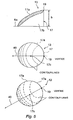
- the reflective subregion 13 shown here is formed by cutting a cylindrical elevated, convex portion 17 obliquely and curving the cut surface as a surface 17a.
- the subregion is designed such that the vertex 19 of the surface 17a and the shape of the surface 17a that is a curved surface are matched to the target exit region.
- This surface 17a does not have any vertical plane (tangential plane) for light incident from a direction vertical to the reflective subregion 13.
- the front end is sharp. Therefore, light reflected from the surface 17a is little reflected to the right side of the reflective plate 1 shown in Fig. 4.
- the reflective subregions 13 at different positions on the reflective plate 1 reflect light to the common exit region 14. Therefore, the direction in which the surface 17a faces the exit region differs slightly at each different position of the reflective subregions 13.
- the straight line 40 connecting the vertex 19 and the center 17c is coincident with the vertical bisector line 16.
- the straight line 40 described above is coincident with the direction of the center 14a of the exit region 14, as shown in Fig. 5C.
- each reflective subregion 13 is fabricated by cutting a cylindrical, elevated convex portion 17 obliquely and curving the cut surface as the surface 17a.
- the structure is not limited to this. It may also be a triangular prism, quadrangular prism, or polygonal prism. Furthermore, plural convex or concave surfaces may be formed on the cut surface.
- each reflective subregion 13 may be formed by appropriately combining plural prismatic convex portions.
- light is reflected to the side of the exit region 14 by varying the height of the surface 17.
- plural reflective subregions 13 having areflective surface formed at a given angle are prepared. The angles of the reflective surfaces of the reflective subregions to a given position are made different from each other.
- the reflective subregions are arrayed from the exit side to reflect light toward the exit region 14.
- each reflective subregion 13 has a reflective surface 20.
- Minute wedge-like convex portions 27b-27d having the reflective surface 20 are substantially right triangles in cross section. Their surfaces are curved.
- exit region 14 it is not necessary that the exit region 14 be within a plane parallel to the reflective plate 1C.
- the exit region may be tilted relative to the surface of the reflective plate 1C.
- the reflective surface 20 is curved toward the convex portions.
- the reflective surface may be planar. In addition, it may be a concave surface.
- plural curved surfaces 21a-21f may be formed as shown in Fig. 7.
- the formation of plural curved surfaces makes it possible to set the direction of the reflective surface at will. Consequently, variations in brightness within the plane of the reflective surface can be prevented. Brightness variations of reflected light can be reduced while enhancing the directivity.
- n 1 of the liquid-crystal layer 38 is assumed to that of the upper substrate 2.
- incident light 7 vertically enters the upper substrate 2 from an air layer 50
- light 8 reflected by the reflective surface 17a refracts as refracted light 8' at the interface between the upper substrate 2 and the air layer 50.
- ⁇ x be the angle of refraction at the air layer 50 corresponding to the center B 2 .
- the angle of refraction corresponding to B 1 is ⁇ x + ⁇ .
- the angle of refraction corresponding to B 2 is ⁇ x .
- the angle of refraction corresponding to B 3 is ⁇ x - ⁇ .
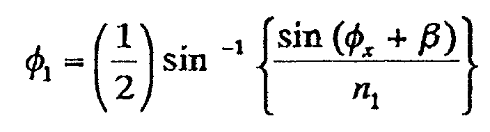
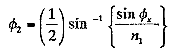
- the angle of refraction 1 (equal to the angle of incidence) corresponding to B 1 is given by
- the angle of refraction i corresponding to B 2 is given by
- the angle of refraction i corresponding to B 3 is given by
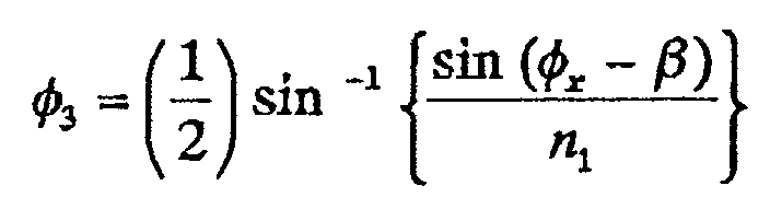
- the tilt ⁇ , or angle of reflection, is calculated, at B 1 , to be
- the tilt is calculated, at B 2 , to be
- the tilt is calculated, at B 3 , to be
- the aforementioned reflective subregions 13 are each made up of one or more concavities or convexes 17 and 18.
- the reflective subregions 13 are essentially regularly or periodically arranged. It is not necessary that their dimensions be uniform. As shown in Fig. 9, they may have random sizes. Furthermore, with respect to their shapes, they may have indeterminate polygonal forms. Therefore, the reflective subregions 13 do not need to be arranged in matrix form. They should be arranged densely in two dimensions, and they form reflective surfaces having almost no flat portions.
- a method of fabricating concave or convex forms used on a reflecting plate is next described.
- the concave or convex forms can be mass-produced with a mold, known as a stamper.
- a photopolymerization (2P method) replication process that is one method of fabricating it is described by referring to Figs. 10A-10D.
- the substrate 11 is prepared.
- An electron-beam resist 22 is applied to it.
- the resist 22 is micro-processed by an electron beam to form convexes.
- a master 23 for the convexes or concavities is fabricated.
- a stamper material such as nickel is deposited on the master 23 by electroforming, thus fabricating a stamper 24.
- the stamper 24 and the master 23 are separated.
- the stamper 24 shows concavities relative to the aforementioned convex form.
- a mold having concavities and convexes is produced.
- a method of fabricating the aforementioned reflective plate is next described by referring to Figs. 11A-11D.
- the stamper 24 is fabricated by electroplating.
- a pattern 24a that is an inversion of the surface topography of the reflective plate is formed on the stamper 24.
- a UV-curable resin 6 is dripped onto a transparent substrate 11 made of a glass substrate. transparent resinous film, or the like. Where the stamper transmits UV radiation, the substrate 11 does not need to be transparent. Then, the stamper 24 is lowered onto the substrate 11 from above the UV-curable resin 6. The UV-curable resin 6 is spread between the substrate 11 and stamper 24 to fill the space between the substrate 11 and stamper 24.
- Fig. 11B UV radiation is directed at the UV-curable resin 6 from the side of the substrate 11 to cure the UV-curable resin 6 by a photocuring reaction.
- the stamper 24 is peeled off from the UV-curable resin 6.
- a pattern 24a that is an inversion of the stamper 24 is transferred as a pattern 6a to the surface of the UV-curable resin 6, as shown in Fig. 11C.
- a thin film of a metal such as Ag or Al is deposited by sputtering or other method on the pattern 6a of the UV-curable resin 6.
- the reflective film 4 is formed as shown in Fig. 11D. Thus, the reflective plate 1 is completed.
- Figs. 12A-12D Another method of fabricating the reflective plate is next described by referring to Figs. 12A-12D.
- the stamper 24 is fabricated by electroforming.
- the pattern 24a that is an inversion of the surface topography of the reflective plate is formed on the stamper 24.
- a resin 30 such as acrylic is spin-coated on the substrate 11. Then, as described in Fig. 12B, the stamper 24 is lowered from above the resin 30 and pushed against the resin 30. As shown in Fig. 12C, an inversion of the inversion pattern 24a of the stamper 24 is transferred as a pattern 30a to the surface of the resin 30.
- a thin metal film such as Ag or Al is deposited on the pattern 30a of the resin 30 by sputtering. As shown in Fig. 12D, a reflective film 4 is formed. In this way, the reflective plate 1 is completed.
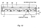
- Fig. 13 schematically shows the structure of a reflective liquid crystal display equipped with the reflective plate fabricated as mentioned above.
- the upper substrate 2 is constructed such that the reflective plate 1 is treated as a rear substrate.
- thin-film transistors (TFTs) 32 are fabricated on the surface of the reflective plate 1 prior to process steps shown in Fig. 11, thus forming the lower substrate 11.
- a pattern of concavities or convexes is created from a light-sensitive resin on the lower substrate 11 as described previously.
- Contact holes 41 are formed at positions corresponding to the TFTs 32.
- a thin metal film is sputtered on the pattern of concavities or convexes and in the contact holes 41.
- the metal film and the reflective film 4 can together form a conductive path that electrically connects the reflective film 4 and the TFTs 32.
- a black matrix 36, color filters 35, and a transparent (ITO) electrode 37 are formed on the rear surface of the upper substrate 2.
- a polarizer (not shown) is stuck on the surface of the upper substrate 2, thus forming a front substrate.
- a liquid-crystal layer 38 is sandwiched between the transparent (ITO) electrode 37 and the reflective plate 4.
- a reflective liquid crystal display is completed.
- the LCD panel and reflective plate are integrated and so the reflective liquid crystal display can be thinned.
- the application of the reflective plate of the present embodiment is not limited to a reflective liquid crystal display.
- the reflective plate can also be used for other reflective display devices.
- the power of the backlight source (not shown) can be reduced.
- the reflective plate can also be used in a so-called semi-transmissive liquid crystal display that takes in incident light from other than the LCD panel.
- a surface reflection type reflective plate has been described in which a pattern of concavities or convexes is formed on the surface of the reflective plate. The incident light is reflected by the surfaces of the concavities or convexes.
- a reflective plate of a rear surface reflection type may also be used in which a substrate is made of glass or transparent resin, A pattern of concavities or convexes is formed on the rear surface of the substrate to reflect incident light.
- a wireless information transmission device 39 such as a cellular phone or low-power consumption wireless device using a reflective liquid crystal display as a display that employs the reflective plate of the present embodiment.
- the present wireless information transmission device 39 constructed in this way is gripped as shown in Fig. 14. Light is incident normal to the monitor screen 39a. Under this condition, the image on the monitor screen 39a can be observed from the upper exit region 14.
- the liquid crystal display can be held at an angle to incident light 7 coming from above.
- the image can be observed at the position of the user 25.
- the incident light 7 reflects as reflected light 7a at the surface 2a of the upper substrate 2. Therefore, the light does not reach the user 25.
- the monitor screen can be observed clearly.
- the present embodiment is not limited to the aforementioned wireless information transmission device 39. Rather, the embodiment can be applied to every electronic apparatus and device equipped with a reflective liquid crystal display typified by mobile information terminals such as personal digital assistants (PDAs) including electronic notes, mobile computers, and mobile TVs.
- PDAs personal digital assistants
- the display screen can be made brighter by using the reflective plate of the present embodiment in a reflective liquid crystal display.
- a reflective LCD is used in a wireless information transmission device or PDA
- backlight can be dispensed with. Therefore, power saving can be accomplished.
- the display can be driven with a battery for a long time.
- the device can be made smaller and cheaper.
- the application is not limited to wireless information transmission devices and PDAs.
- the display screen can be made brighter. The visibility can be improved. Furthermore, directivity is imparted to visual observation and so it is also possible to prevent other persons from peeping from a side.
- light can be collected onto a given surface area by reflective subregions and utilized efficiently.
- a given areal region can be totally made bright by using the reflective plate and a display device in combination. In this way, a crisp image can be observed.
Landscapes
- Physics & Mathematics (AREA)
- Nonlinear Science (AREA)
- General Physics & Mathematics (AREA)
- Optics & Photonics (AREA)
- Mathematical Physics (AREA)
- Chemical & Material Sciences (AREA)
- Crystallography & Structural Chemistry (AREA)
- Liquid Crystal (AREA)
- Optical Elements Other Than Lenses (AREA)
- Devices For Indicating Variable Information By Combining Individual Elements (AREA)
Abstract
Description




Claims (10)
- A reflective plate having a plurality of reflective subregions each of which has at least one reflective surface for reflecting light, the light reflected from said reflective subregions forming spreads of exit, said spreads of exit intersecting each other at a given upper position to form a common exit region,
wherein said reflective subregions are so arranged that light rays incident on the reflective plate from a vertical direction are reflected substantially toward a center of the exit region located outside a region lying vertically above the reflective plate and that centers of intensities of the reflected light rays concentrate at the center of said exit region. - The reflective plate of claim 1, characterized in that said reflective surfaces of said reflective subregions have different shapes according to different installation locations.
- The reflective plate of claim 1, characterized in that said reflective subregions are so arranged that an angle formed between light incident on each reflective subregion and reflected light arising from said incident light decreases in approaching the center of said exit region.
- The reflective plate of claim 1, characterized in that each of said reflective subregions has a plurality of curved surfaces on its surface facing said exit region.
- The reflective plate of claim 1, characterized in that said plural reflective subregions are arranged coaxially from a projection point obtained by projecting the center of said exit region onto a plane including said reflective plate, and that normal lines to tilted surfaces of said reflective subregions are tilted toward said projection point, said normal lines having the same tilt angle on the same coaxial circle.
- The reflective plate of claim 1, characterized in that the center of said exit region exists within a virtual plane normal to the surface of said reflective plate on a substantially bisector line of said reflective plate.
- A liquid crystal display having first and second substrates disposed opposite to each other, a liquid-crystal layer consisting of a liquid crystal sealed in between the first and second substrates, and a reflective layer formed on said second substrate and having a plurality of reflective subregions, each of said reflective subregions having at least one reflective surface for reflecting light;
wherein first incident light incident from a given direction on a surface of said first substrate that faces away from said liquid-crystal layer is divided into at least first reflected light and second incident light, said first reflected light being produced by regular reflection at the surface of said first substrate, said second incident light reaching said reflective subregions via said first substrate and via said liquid-crystal layer;
wherein said second incident light is reflected from the reflective subregions, forming second reflected light that forms plural spreads of exit, said spreads of exit intersecting each other at a given position above said first substrate, thus forming a common exit region;
wherein said second reflected light is reflected substantially toward a center of said exit region, centers of intensities of the reflected light rays concentrating at the center of said exit region; and
wherein said reflective subregions are so arranged that the center of said exit region is formed in a given position not in the direction of travel of said first reflected light. - The liquid crystal display of claim 7, characterized in that the center of said exit region exists within a virtual plane normal to the surface of the second substrate on a substantially bisector line of said second substrate.
- Electronic apparatus having a display portion including a liquid crystal display having first and second substrates disposed opposite to each other, a liquid-crystal layer consisting of a liquid crystal sealed in between the first and second substrates, and a reflective layer formed on said second substrate and having a plurality of reflective subregions, each of said reflective subregions having at least one reflective surface for reflecting light;
wherein first incident light incident from a given direction on a surface of said first substrate that faces away from said liquid-crystal layer is divided into at least first reflected light and second incident light, said first reflected light being produced by regular reflection at the surface of said first substrate, said second incident light reaching said reflective subregions via said first substrate and via said liquid-crystal layer;
wherein said second incident light is reflected from said reflective subregions, forming second reflected light which forms plural spreads of exit, said spreads of exit intersecting each other at a given position above said first substrate, thus forming a common exit region;
wherein said second reflected light is reflected substantially toward a center of said exit region, centers of intensities of the reflected light rays concentrating at the center of said exit region; and
wherein said reflective subregions are so arranged that the center of said exit region is formed in a given position not in the direction of travel of said first reflected light - A method of reflecting light by a reflective plate having plural reflective subregions each having at least one reflective surface for reflecting light, light reflected from said reflective subregions forming plural spreads of exit which intersect each other at a given upper position to thereby form a common exit region, said method comprising the steps of:causing said light to enter said reflective plate as incident light from a vertical direction;reflecting said incident light by said plural reflective subregions;directing light rays reflected by said reflective subregions substantially toward a center of said exit region located outside a region lying vertically above said reflective plate; andconcentrating centers of intensities of said reflected light rays at the center of said exit region.
Applications Claiming Priority (2)
| Application Number | Priority Date | Filing Date | Title |
|---|---|---|---|
| JP2001072468 | 2001-03-14 | ||
| JP2001072468A JP2002267821A (en) | 2001-03-14 | 2001-03-14 | Reflector, liquid crystal display using the reflector, and electronic equipment using the liquid crystal display |
Publications (2)
| Publication Number | Publication Date |
|---|---|
| EP1243964A2 true EP1243964A2 (en) | 2002-09-25 |
| EP1243964A3 EP1243964A3 (en) | 2005-06-29 |
Family
ID=18930047
Family Applications (1)
| Application Number | Title | Priority Date | Filing Date |
|---|---|---|---|
| EP02251751A Withdrawn EP1243964A3 (en) | 2001-03-14 | 2002-03-12 | Reflective plate, liquid crystal display (LCD) using same, and electronic apparatus using this LCD |
Country Status (5)
| Country | Link |
|---|---|
| US (1) | US7057685B2 (en) |
| EP (1) | EP1243964A3 (en) |
| JP (1) | JP2002267821A (en) |
| KR (1) | KR100448553B1 (en) |
| CN (1) | CN1223886C (en) |
Cited By (1)
| Publication number | Priority date | Publication date | Assignee | Title |
|---|---|---|---|---|
| EP4544351A4 (en) * | 2022-06-24 | 2026-06-17 | Corning Inc | REFLECTIVE INDICATORS WITH REFLECTORS |
Families Citing this family (7)
| Publication number | Priority date | Publication date | Assignee | Title |
|---|---|---|---|---|
| JP2004264561A (en) * | 2003-02-28 | 2004-09-24 | Omron Corp | Reflection plate, display device using the reflection plate, and electronic device using the display device |
| JP2007212969A (en) * | 2006-02-13 | 2007-08-23 | Nec Lcd Technologies Ltd | REFLECTOR, LIQUID CRYSTAL DISPLAY DEVICE PROVIDED WITH THE REFLECTOR AND MANUFACTURING METHOD THEREOF |
| JP2008065102A (en) * | 2006-09-08 | 2008-03-21 | Alps Electric Co Ltd | Reflection plate and liquid crystal display apparatus |
| US7715103B2 (en) * | 2007-09-10 | 2010-05-11 | Microvision, Inc. | Buried numerical aperture expander having transparent properties |
| JP5730081B2 (en) * | 2011-03-08 | 2015-06-03 | 株式会社ジャパンディスプレイ | Display device |
| US9798066B2 (en) * | 2014-08-18 | 2017-10-24 | New Optics, Ltd | Display device and light guide plate thereof |
| EP3231578A4 (en) * | 2014-12-10 | 2018-08-22 | Toppan Printing Co., Ltd. | Embossed sheet and decorative sheet |
Family Cites Families (10)
| Publication number | Priority date | Publication date | Assignee | Title |
|---|---|---|---|---|
| US4185895A (en) * | 1978-03-31 | 1980-01-29 | Hughes Aircraft Company | Reflective mode, dynamic scattering liquid crystal display system having a Fresnel reflector for lighting |
| CH633381A5 (en) * | 1978-12-20 | 1982-11-30 | Bbc Brown Boveri & Cie | ELECTROOPTICAL DISPLAY WITH REFLECTOR. |
| WO1982004326A1 (en) * | 1981-05-25 | 1982-12-09 | Masataka Negishi | Optical width and direction converter |
| US5128787A (en) * | 1990-12-07 | 1992-07-07 | At&T Bell Laboratories | Lcd display with multifaceted back reflector |
| US6097458A (en) * | 1995-12-11 | 2000-08-01 | Sharp Kabushiki Kaisha | Reflector, reflective liquid crystal display incorporating the same and method for fabricating the same |
| US6199992B1 (en) * | 1997-03-13 | 2001-03-13 | Alps Electric Co., Ltd. | Reflector, method of manufacturing the same, and display device using the reflector |
| US6285426B1 (en) * | 1998-07-06 | 2001-09-04 | Motorola, Inc. | Ridged reflector having optically transmissive properties for an optical display device |
| KR100546704B1 (en) * | 1998-12-16 | 2006-03-23 | 엘지.필립스 엘시디 주식회사 | Reflector of Reflective Liquid Crystal Display |
| US6563559B2 (en) * | 2000-02-02 | 2003-05-13 | Sanyo Electric Co., Ltd. | Reflective liquid crystal display having increase luminance for each display pixel |
| JP3649145B2 (en) * | 2000-12-28 | 2005-05-18 | オムロン株式会社 | REFLECTIVE DISPLAY DEVICE, ITS MANUFACTURING METHOD, AND DEVICE USING THE SAME |
-
2001
- 2001-03-14 JP JP2001072468A patent/JP2002267821A/en active Pending
-
2002
- 2002-03-12 KR KR10-2002-0013160A patent/KR100448553B1/en not_active Expired - Fee Related
- 2002-03-12 EP EP02251751A patent/EP1243964A3/en not_active Withdrawn
- 2002-03-13 CN CNB021073228A patent/CN1223886C/en not_active Expired - Fee Related
- 2002-03-14 US US10/097,481 patent/US7057685B2/en not_active Expired - Fee Related
Cited By (1)
| Publication number | Priority date | Publication date | Assignee | Title |
|---|---|---|---|---|
| EP4544351A4 (en) * | 2022-06-24 | 2026-06-17 | Corning Inc | REFLECTIVE INDICATORS WITH REFLECTORS |
Also Published As
| Publication number | Publication date |
|---|---|
| EP1243964A3 (en) | 2005-06-29 |
| JP2002267821A (en) | 2002-09-18 |
| CN1375728A (en) | 2002-10-23 |
| CN1223886C (en) | 2005-10-19 |
| KR100448553B1 (en) | 2004-09-13 |
| US20020159009A1 (en) | 2002-10-31 |
| KR20020073270A (en) | 2002-09-23 |
| US7057685B2 (en) | 2006-06-06 |
Similar Documents
| Publication | Publication Date | Title |
|---|---|---|
| CN111665591B (en) | Light guide plate, backlight module and liquid crystal display module | |
| EP1933178B1 (en) | Optical sheet and method for fabricating the same | |
| KR100425348B1 (en) | Reflector and reflective liquid crystal display | |
| KR100446562B1 (en) | Translucent Liquid Crystal Display Device | |
| KR100478574B1 (en) | Reflector and reflective liquid crystal display | |
| EP1455203A1 (en) | Prism sheet, back light unit using the prism sheet, and transmissive liquid crystal display device | |
| EP1586920A2 (en) | Lighting system, image display apparatus using the same and light diffuson plate used therefor | |
| US20040105157A1 (en) | Optical component for liquid crystal display | |
| US6606139B2 (en) | Liquid crystal display device with improved viewing angle property and portable electronic apparatus using the same | |
| KR20020037443A (en) | Reflective display device and prism array sheet | |
| EP1143269B1 (en) | Optical path changing polarizer | |
| JP2003098325A (en) | Transflective reflector and transflective liquid crystal display | |
| US7658502B2 (en) | Back light structure of liquid crystal display device | |
| EP1521114A1 (en) | Reflector and liquid crystal display device using the same | |
| US7321407B2 (en) | Reflector and liquid crystal display | |
| US7057685B2 (en) | Reflective plate, liquid crystal display (LCD) using same, and electronic apparatus using this LCD | |
| US6995819B2 (en) | Semi-transmissive liquid crystal display device | |
| JP3744422B2 (en) | Reflecting member and manufacturing method thereof | |
| JP2003202563A (en) | Liquid crystal display | |
| JPWO2001035129A1 (en) | Reflective member and light reflecting method | |
| EP1271190B1 (en) | Reflector and reflective liquid crystal display | |
| KR100635898B1 (en) | Reflector and liquid crystal display device | |
| KR20070106397A (en) | Optical film and back light unit having the same | |
| US6816216B2 (en) | Optical component and reflective plate, and device using the same optical component | |
| JP2000048617A (en) | Light guide plate, surface light source device and reflection type liquid crystal display device |
Legal Events
| Date | Code | Title | Description |
|---|---|---|---|
| PUAI | Public reference made under article 153(3) epc to a published international application that has entered the european phase |
Free format text: ORIGINAL CODE: 0009012 |
|
| AK | Designated contracting states |
Kind code of ref document: A2 Designated state(s): AT BE CH CY DE DK ES FI FR GB GR IE IT LI LU MC NL PT SE TR |
|
| AX | Request for extension of the european patent |
Free format text: AL;LT;LV;MK;RO;SI |
|
| PUAL | Search report despatched |
Free format text: ORIGINAL CODE: 0009013 |
|
| RIC1 | Information provided on ipc code assigned before grant |
Ipc: 7G 02B 5/08 B Ipc: 7G 02F 1/1335 A |
|
| AK | Designated contracting states |
Kind code of ref document: A3 Designated state(s): AT BE CH CY DE DK ES FI FR GB GR IE IT LI LU MC NL PT SE TR |
|
| AX | Request for extension of the european patent |
Extension state: AL LT LV MK RO SI |
|
| 17P | Request for examination filed |
Effective date: 20050809 |
|
| AKX | Designation fees paid |
Designated state(s): AT BE CH CY DE DK ES FI FR GB GR IE IT LI LU MC NL PT SE TR |
|
| STAA | Information on the status of an ep patent application or granted ep patent |
Free format text: STATUS: THE APPLICATION IS DEEMED TO BE WITHDRAWN |
|
| 18D | Application deemed to be withdrawn |
Effective date: 20090317 |