EP1243805A2 - Centrifugal clutch - Google Patents
Centrifugal clutch Download PDFInfo
- Publication number
- EP1243805A2 EP1243805A2 EP02006150A EP02006150A EP1243805A2 EP 1243805 A2 EP1243805 A2 EP 1243805A2 EP 02006150 A EP02006150 A EP 02006150A EP 02006150 A EP02006150 A EP 02006150A EP 1243805 A2 EP1243805 A2 EP 1243805A2
- Authority
- EP
- European Patent Office
- Prior art keywords
- clutch
- engine
- driving member
- centrifugally operated
- speed
- Prior art date
- Legal status (The legal status is an assumption and is not a legal conclusion. Google has not performed a legal analysis and makes no representation as to the accuracy of the status listed.)
- Granted
Links
Images



Classifications
-
- F—MECHANICAL ENGINEERING; LIGHTING; HEATING; WEAPONS; BLASTING
- F16—ENGINEERING ELEMENTS AND UNITS; GENERAL MEASURES FOR PRODUCING AND MAINTAINING EFFECTIVE FUNCTIONING OF MACHINES OR INSTALLATIONS; THERMAL INSULATION IN GENERAL
- F16D—COUPLINGS FOR TRANSMITTING ROTATION; CLUTCHES; BRAKES
- F16D43/00—Automatic clutches
- F16D43/02—Automatic clutches actuated entirely mechanically
- F16D43/04—Automatic clutches actuated entirely mechanically controlled by angular speed
- F16D43/06—Automatic clutches actuated entirely mechanically controlled by angular speed with centrifugal masses actuating axially a movable pressure ring or the like
- F16D43/08—Automatic clutches actuated entirely mechanically controlled by angular speed with centrifugal masses actuating axially a movable pressure ring or the like the pressure ring actuating friction plates, cones or similar axially-movable friction surfaces
-
- B—PERFORMING OPERATIONS; TRANSPORTING
- B60—VEHICLES IN GENERAL
- B60W—CONJOINT CONTROL OF VEHICLE SUB-UNITS OF DIFFERENT TYPE OR DIFFERENT FUNCTION; CONTROL SYSTEMS SPECIALLY ADAPTED FOR HYBRID VEHICLES; ROAD VEHICLE DRIVE CONTROL SYSTEMS FOR PURPOSES NOT RELATED TO THE CONTROL OF A PARTICULAR SUB-UNIT
- B60W10/00—Conjoint control of vehicle sub-units of different type or different function
- B60W10/02—Conjoint control of vehicle sub-units of different type or different function including control of driveline clutches
-
- B—PERFORMING OPERATIONS; TRANSPORTING
- B60—VEHICLES IN GENERAL
- B60W—CONJOINT CONTROL OF VEHICLE SUB-UNITS OF DIFFERENT TYPE OR DIFFERENT FUNCTION; CONTROL SYSTEMS SPECIALLY ADAPTED FOR HYBRID VEHICLES; ROAD VEHICLE DRIVE CONTROL SYSTEMS FOR PURPOSES NOT RELATED TO THE CONTROL OF A PARTICULAR SUB-UNIT
- B60W10/00—Conjoint control of vehicle sub-units of different type or different function
- B60W10/04—Conjoint control of vehicle sub-units of different type or different function including control of propulsion units
- B60W10/06—Conjoint control of vehicle sub-units of different type or different function including control of propulsion units including control of combustion engines
-
- B—PERFORMING OPERATIONS; TRANSPORTING
- B60—VEHICLES IN GENERAL
- B60W—CONJOINT CONTROL OF VEHICLE SUB-UNITS OF DIFFERENT TYPE OR DIFFERENT FUNCTION; CONTROL SYSTEMS SPECIALLY ADAPTED FOR HYBRID VEHICLES; ROAD VEHICLE DRIVE CONTROL SYSTEMS FOR PURPOSES NOT RELATED TO THE CONTROL OF A PARTICULAR SUB-UNIT
- B60W10/00—Conjoint control of vehicle sub-units of different type or different function
- B60W10/10—Conjoint control of vehicle sub-units of different type or different function including control of change-speed gearings
-
- B—PERFORMING OPERATIONS; TRANSPORTING
- B60—VEHICLES IN GENERAL
- B60W—CONJOINT CONTROL OF VEHICLE SUB-UNITS OF DIFFERENT TYPE OR DIFFERENT FUNCTION; CONTROL SYSTEMS SPECIALLY ADAPTED FOR HYBRID VEHICLES; ROAD VEHICLE DRIVE CONTROL SYSTEMS FOR PURPOSES NOT RELATED TO THE CONTROL OF A PARTICULAR SUB-UNIT
- B60W30/00—Purposes of road vehicle drive control systems not related to the control of a particular sub-unit, e.g. of systems using conjoint control of vehicle sub-units
- B60W30/18—Propelling the vehicle
-
- B—PERFORMING OPERATIONS; TRANSPORTING
- B60—VEHICLES IN GENERAL
- B60W—CONJOINT CONTROL OF VEHICLE SUB-UNITS OF DIFFERENT TYPE OR DIFFERENT FUNCTION; CONTROL SYSTEMS SPECIALLY ADAPTED FOR HYBRID VEHICLES; ROAD VEHICLE DRIVE CONTROL SYSTEMS FOR PURPOSES NOT RELATED TO THE CONTROL OF A PARTICULAR SUB-UNIT
- B60W30/00—Purposes of road vehicle drive control systems not related to the control of a particular sub-unit, e.g. of systems using conjoint control of vehicle sub-units
- B60W30/18—Propelling the vehicle
- B60W30/18009—Propelling the vehicle related to particular drive situations
- B60W30/18027—Drive off, accelerating from standstill
-
- F—MECHANICAL ENGINEERING; LIGHTING; HEATING; WEAPONS; BLASTING
- F02—COMBUSTION ENGINES; HOT-GAS OR COMBUSTION-PRODUCT ENGINE PLANTS
- F02D—CONTROLLING COMBUSTION ENGINES
- F02D41/00—Electrical control of supply of combustible mixture or its constituents
- F02D41/02—Circuit arrangements for generating control signals
- F02D41/021—Introducing corrections for particular conditions exterior to the engine
- F02D41/0215—Introducing corrections for particular conditions exterior to the engine in relation with elements of the transmission
- F02D41/022—Introducing corrections for particular conditions exterior to the engine in relation with elements of the transmission in relation with the clutch status
-
- F—MECHANICAL ENGINEERING; LIGHTING; HEATING; WEAPONS; BLASTING
- F16—ENGINEERING ELEMENTS AND UNITS; GENERAL MEASURES FOR PRODUCING AND MAINTAINING EFFECTIVE FUNCTIONING OF MACHINES OR INSTALLATIONS; THERMAL INSULATION IN GENERAL
- F16D—COUPLINGS FOR TRANSMITTING ROTATION; CLUTCHES; BRAKES
- F16D43/00—Automatic clutches
- F16D43/02—Automatic clutches actuated entirely mechanically
- F16D43/04—Automatic clutches actuated entirely mechanically controlled by angular speed
- F16D43/14—Automatic clutches actuated entirely mechanically controlled by angular speed with centrifugal masses actuating the clutching members directly in a direction which has at least a radial component; with centrifugal masses themselves being the clutching members
- F16D43/18—Automatic clutches actuated entirely mechanically controlled by angular speed with centrifugal masses actuating the clutching members directly in a direction which has at least a radial component; with centrifugal masses themselves being the clutching members with friction clutching members
-
- B—PERFORMING OPERATIONS; TRANSPORTING
- B60—VEHICLES IN GENERAL
- B60W—CONJOINT CONTROL OF VEHICLE SUB-UNITS OF DIFFERENT TYPE OR DIFFERENT FUNCTION; CONTROL SYSTEMS SPECIALLY ADAPTED FOR HYBRID VEHICLES; ROAD VEHICLE DRIVE CONTROL SYSTEMS FOR PURPOSES NOT RELATED TO THE CONTROL OF A PARTICULAR SUB-UNIT
- B60W50/00—Details of control systems for road vehicle drive control not related to the control of a particular sub-unit, e.g. process diagnostic or vehicle driver interfaces
- B60W2050/0001—Details of the control system
- B60W2050/0043—Signal treatments, identification of variables or parameters, parameter estimation or state estimation
- B60W2050/0044—In digital systems
- B60W2050/0045—In digital systems using databus protocols
-
- B—PERFORMING OPERATIONS; TRANSPORTING
- B60—VEHICLES IN GENERAL
- B60W—CONJOINT CONTROL OF VEHICLE SUB-UNITS OF DIFFERENT TYPE OR DIFFERENT FUNCTION; CONTROL SYSTEMS SPECIALLY ADAPTED FOR HYBRID VEHICLES; ROAD VEHICLE DRIVE CONTROL SYSTEMS FOR PURPOSES NOT RELATED TO THE CONTROL OF A PARTICULAR SUB-UNIT
- B60W2510/00—Input parameters relating to a particular sub-units
- B60W2510/06—Combustion engines, Gas turbines
- B60W2510/0604—Throttle position
-
- B—PERFORMING OPERATIONS; TRANSPORTING
- B60—VEHICLES IN GENERAL
- B60W—CONJOINT CONTROL OF VEHICLE SUB-UNITS OF DIFFERENT TYPE OR DIFFERENT FUNCTION; CONTROL SYSTEMS SPECIALLY ADAPTED FOR HYBRID VEHICLES; ROAD VEHICLE DRIVE CONTROL SYSTEMS FOR PURPOSES NOT RELATED TO THE CONTROL OF A PARTICULAR SUB-UNIT
- B60W2510/00—Input parameters relating to a particular sub-units
- B60W2510/06—Combustion engines, Gas turbines
- B60W2510/0638—Engine speed
-
- B—PERFORMING OPERATIONS; TRANSPORTING
- B60—VEHICLES IN GENERAL
- B60W—CONJOINT CONTROL OF VEHICLE SUB-UNITS OF DIFFERENT TYPE OR DIFFERENT FUNCTION; CONTROL SYSTEMS SPECIALLY ADAPTED FOR HYBRID VEHICLES; ROAD VEHICLE DRIVE CONTROL SYSTEMS FOR PURPOSES NOT RELATED TO THE CONTROL OF A PARTICULAR SUB-UNIT
- B60W2510/00—Input parameters relating to a particular sub-units
- B60W2510/10—Change speed gearings
- B60W2510/1005—Transmission ratio engaged
-
- B—PERFORMING OPERATIONS; TRANSPORTING
- B60—VEHICLES IN GENERAL
- B60W—CONJOINT CONTROL OF VEHICLE SUB-UNITS OF DIFFERENT TYPE OR DIFFERENT FUNCTION; CONTROL SYSTEMS SPECIALLY ADAPTED FOR HYBRID VEHICLES; ROAD VEHICLE DRIVE CONTROL SYSTEMS FOR PURPOSES NOT RELATED TO THE CONTROL OF A PARTICULAR SUB-UNIT
- B60W2552/00—Input parameters relating to infrastructure
- B60W2552/15—Road slope, i.e. the inclination of a road segment in the longitudinal direction
-
- B—PERFORMING OPERATIONS; TRANSPORTING
- B60—VEHICLES IN GENERAL
- B60W—CONJOINT CONTROL OF VEHICLE SUB-UNITS OF DIFFERENT TYPE OR DIFFERENT FUNCTION; CONTROL SYSTEMS SPECIALLY ADAPTED FOR HYBRID VEHICLES; ROAD VEHICLE DRIVE CONTROL SYSTEMS FOR PURPOSES NOT RELATED TO THE CONTROL OF A PARTICULAR SUB-UNIT
- B60W2710/00—Output or target parameters relating to a particular sub-units
- B60W2710/06—Combustion engines, Gas turbines
- B60W2710/0644—Engine speed
-
- B—PERFORMING OPERATIONS; TRANSPORTING
- B60—VEHICLES IN GENERAL
- B60W—CONJOINT CONTROL OF VEHICLE SUB-UNITS OF DIFFERENT TYPE OR DIFFERENT FUNCTION; CONTROL SYSTEMS SPECIALLY ADAPTED FOR HYBRID VEHICLES; ROAD VEHICLE DRIVE CONTROL SYSTEMS FOR PURPOSES NOT RELATED TO THE CONTROL OF A PARTICULAR SUB-UNIT
- B60W2710/00—Output or target parameters relating to a particular sub-units
- B60W2710/06—Combustion engines, Gas turbines
- B60W2710/0666—Engine torque
-
- B—PERFORMING OPERATIONS; TRANSPORTING
- B60—VEHICLES IN GENERAL
- B60Y—INDEXING SCHEME RELATING TO ASPECTS CROSS-CUTTING VEHICLE TECHNOLOGY
- B60Y2200/00—Type of vehicle
- B60Y2200/10—Road Vehicles
- B60Y2200/14—Trucks; Load vehicles, Busses
-
- F—MECHANICAL ENGINEERING; LIGHTING; HEATING; WEAPONS; BLASTING
- F02—COMBUSTION ENGINES; HOT-GAS OR COMBUSTION-PRODUCT ENGINE PLANTS
- F02D—CONTROLLING COMBUSTION ENGINES
- F02D41/00—Electrical control of supply of combustible mixture or its constituents
- F02D41/02—Circuit arrangements for generating control signals
- F02D41/021—Introducing corrections for particular conditions exterior to the engine
- F02D41/0215—Introducing corrections for particular conditions exterior to the engine in relation with elements of the transmission
Definitions
- the present invention relates to a centrifugal master clutch and a vehicular transmission system utilizing same.
- the present invention relates to an automated vehicular transmission system comprising an engine, a multiple ratio transmission, a centrifugally operated master friction clutch for drivingly coupling the engine to the transmission and a controller for controlling fueling of the engine during vehicle launch conditions, as a function of throttle position and other sensed system operating conditions such as at least one of engine speed, transmission input shaft speed, transmission output shaft speed, engine torque and engaged gear ratio.
- a preferred embodiment of the present invention relates to a vehicular centrifugal master friction clutch adapted to be utilized in an automated mechanical transmission system.
- Centrifugally operated friction clutches are well known in the prior art and typically include a driving input member driven by a prime mover, usually an electric motor or internal combustion engine, and weights rotatable with the driving member which, upon rotation of the driving member, will move radially outwardly under the effect of centrifugal force to cause the driving input member to frictionally engage a driven output member.
- a prime mover usually an electric motor or internal combustion engine
- weights rotatable with the driving member which, upon rotation of the driving member, will move radially outwardly under the effect of centrifugal force to cause the driving input member to frictionally engage a driven output member.
- Examples of centrifugally operated clutches may be seen by reference to U.S. Patent No.'s: 3,580,372; 3,580,372; 3,696,901; 5,437,356; 3,810,533; 4,819,779; 5,441,137; 5,730,269; and; 4,610,343, the disclosures of which
- Fully or partially automated mechanical transmission systems that, upon determining that a dynamic shift from a currently engaged ratio into neutral and then into a target ratio is desirable, will, while maintaining the vehicle master friction clutch engaged, initiate automatic fuel control to cause reduced torque across the jaw clutches to be disengaged, are known in the prior art as may be seen by reference to U.S. Patent No.'s: 4,850,236; 5,820,104; 5,582,558; 5,735,771; 5,775,639; 6,015,366; and 6,126,570, the disclosures of which are incorporated herein by reference. These systems include systems that attempt to fuel the engine to achieve a sustained zero driveline torque, and systems which force torque reversals, see U.S. Patent No.: 4,850,236. These systems, upon sensing a neutral condition, will, while maintaining the master clutch engaged, cause the engine to rotate at a speed determined to cause synchronous conditions for engaging the target ratio.
- Vehicular driveline systems especially for heavy-duty vehicles, utilizing centrifugal clutches have not been satisfactory as the engines were typically controlled by throttle device position, not on a closed loop basis based upon a target engine speed and/or engine torque, and thus did not provide acceptable control for smooth vehicle launch and low speed operation.
- Prior art vehicular driveline systems utilizing centrifugal master clutches where not provided with clutches having damage and/or overheating protection and/or were not configured to lock up and release at engine speeds selected to permit dynamic shifting with the master clutch engaged.
- the drawbacks of the prior art are reduced or minimized by the provision of a centrifugal master friction clutch, and a vehicular automated transmission system utilizing same, which utilizes closed loop control to provide acceptable performance for heavy duty vehicle launch operations and low speed operation and is configured to allow dynamic shifting with the master clutch engaged.
- the closed loop control will provide protection from damage and/or overheating.
- centrifugal clutch structure which will initially lockup at an engine speed below the speed at which upshifts are required and will not release from a lockup condition at engine speeds above (i) the highest speeds at which down shifts are required and (ii) the lowest allowable expected engine speed after completion of an upshift and by controlling fueling of the engine during launch to cause engine speed and/or engine torque to equal or not exceed a target value determined as a function of sensed input signal values indicative of two or more of throttle device position, engine speed, engine torque, transmission input shaft speed, transmission output shaft speed, transmission engaged ratio and clutch slip.
- the centrifugal master clutch requires no external clutch actuator or sensor, and no connections to mechanical linkages, electrical power and/or fluid power.
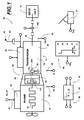
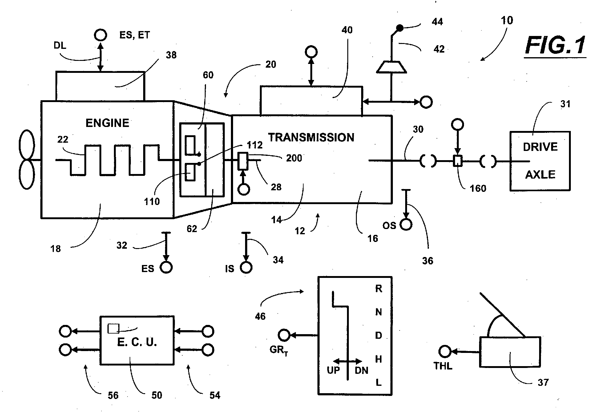
- Fig. 1 is a schematic illustration of a vehicular drivetrain using the centrifugal clutch and engine fuel control of the present invention.
- Fig. 2 is a schematic illustration, in graphical format, of the clamp force characteristics of the centrifugal clutch of the present invention at various engine speeds.
- Fig. 3 is a schematic illustration, in graphical format, of target engine speeds for various throttle positions at vehicle launch for the system of the present invention.
- Fig. 4 is a partial top view, in section, of the cover and centrifugal mechanism of the centrifugal clutch of the present invention.
- Fig. 5 is a partial sectional view of the roller, ramp, and clamp force limiting spring mechanism utilized with the centrifugal mechanism.
- Fig 6A and 6B are partial sectional views illustrating the position of the flyweights in the fully radially inward clutch disengaged position and the fueling radially outward clutch fully engaged position, respectively.
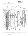
- Fig. 7 is a schematic partial sectional view of the present invention.
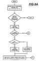
- Fig. 8A and 8B are schematic illustrations, in flowchart format, of the launch logic of the present invention.
- System 10 may be fully automated, as seen by way of example in U.S. Patent No.: 4,361,060, partially automated, as seen by way of example in U.S. Patent No's: 4,648,290 and 5,409,432, or manual with controller assist, as seen by way of example in U.S. Patent No's: 4,850,236; 5,582,558; 5,735,771; and 6,015,366.
- a change-gear transmission 12 comprising a main transmission section 14 connected in series with a splitter-type auxiliary transmission section 16 is drivingly connected to an internal combustion engine 18, such as a well-known gasoline or diesel engine, by the centrifugal master friction clutch 20 of the present invention.
- Transmissions 12 may be of the type well known in the prior art and are sold by the assignee of this application, EATON CORPORATION, under the trademarks "Super-10” and "Lightning", and may be seen in greater detail by reference to U.S. Pat. No's: 4,754,665; 6,015,366; 5,370,013; 5,974,906; and 5,974,354, the disclosures of which are incorporated herein by reference.
- Engine 18 includes a crankshaft 22, which is attached to a driving member 60 of centrifugal master clutch 20, which frictionally engages with, and disengages from, a driven member 62, which is attached to the input shaft 28 of the transmission.
- a transmission output shaft 30 extends from the auxiliary transmission section 16 for driving connection to the vehicular drive wheels, as through a drive axle 31 or transfer case.
- engaged and disengaged as used in connection with a master friction clutch refer to the capacity, or lack of capacity, respectively, of the clutch to transfer a significant amount of torque. Mere random contact of the friction surfaces, in the absence of at least a minimal clamping force, is not considered engagement.
- centrifugal clutch 20 requires no external clutch actuator and is operated as function of the rotational speed (ES) of the engine. Centrifugal clutch 20 also requires no connections to operating linkages, command signal inputs, power electronics and/or compressed air and/or hydraulic conduits. The most economical application of the present invention is with a dry clutch, however, the present invention is also applicable to wet clutch technology.
- Transmission system 10 further includes rotational speed sensors 32 for sensing engine rotational speed (ES), 34 for sensing input shaft rotational speed (IS), and 36 for sensing output shaft rotational speed (OS), and providing signals indicative thereof.
- a sensor 37 provides a signal THL indicative of throttle pedal position or of torque demand. The signal is usually a percentage (0% to 100%) of fuel throttle position.
- Engine 18 may be electronically controlled, including an electronic controller 38 communicating over an electronic data link (DL) operating under an industry standard protocol such as SAE J-1922, SAE J-1939, ISO 11898 or the like.
- DL electronic data link
- An X-Y shift actuator which by way of example may be of the types illustrated in U.S. Pat. No's: 5,481,170; 5,281,902; 4,899,609; and 4,821,590, may be provided for automated or shift-by-wire shifting of the transmission main section and/or auxiliary section.
- a manually operated shift lever 42 having a shift knob 44 thereon may be provided.
- Shift knob 44 may be of the type described in aforementioned U.S. Pat. No: 5,957,001.
- shift lever 42 is manually manipulated in a known shift pattern for selective engagement and disengagement of various shift ratios.
- Shift Knob 44 may include an intent to shift switch 44A by which the vehicle operator will request automatic engine fueling control to relieve torque lock and allow a shift to transmission neutral.
- a shift selector 46 allows the vehicle driver to select a mode of operation and provides a signal GR T indicative thereof.
- System 10 includes a control unit 50, preferably a microprocessor-based control unit of the type illustrated in U.S. Pat. No's: 4,595,986; 4,361,065; and 5,335,566, the disclosures of which are incorporated herein by reference, for receiving input signals 54 and processing same according to predetermined logic rules to issue command output signals 56 to system actuators, such as engine controller 38, shift actuator 40, and the like.
- a control unit 50 preferably a microprocessor-based control unit of the type illustrated in U.S. Pat. No's: 4,595,986; 4,361,065; and 5,335,566, the disclosures of which are incorporated herein by reference, for receiving input signals 54 and processing same according to predetermined logic rules to issue command output signals 56 to system actuators, such as engine controller 38, shift actuator 40, and the like.
- torque lock can be relieved by fueling the engine to cause assumed zero driveline torque and/or by forcing torque reversals, which will positively cause crossings of zero driveline torque.
- Fully or partially automated mechanical transmission systems that, upon determining that a shift from a currently engaged ratio into neutral and then into a target ratio is desirable, will, while maintaining the vehicle master friction clutch engaged, initiate automatic fuel control to cause reduced torque across the jaw clutches to be disengaged, are also known in the prior art as may be seen by reference to above-mentioned U.S. Patent No.'s: 4,850,236; 5,582,558; 5,735,771; 5,775,639; 6,015,366; and 6,126,570. Shifting with the master clutch remaining engaged is preferred in many situations, as such shifts tend to be of a higher shift quality and/or cause less wear on the driveline.
- Engine torque refers to a value indicative of an engine torque, usually gross engine torque, from which an output or flywheel torque may be calculated or estimated. The relationship of gross engine torque to flywheel torque is discussed in U.S. Pat. No's: 5,509,867 and 5,490,063, the disclosures of which are incorporated herein by reference.
- One or more engine torque's or torque limit values may be commanded on, or read from, an industry standard data link, DL, such as an SAE J-1922, SAE J-1939 or ISO11898 compliant datalink.
- DL industry standard data link
- Many input/informational signals such as engine speed (ES), engine torque (ET), and the like may also be carried by the datalink.
- Clutch 20 includes an input or driving portion 60 fixed for rotation with engine crankshaft 22 (usually at the engine flywheel), and an output or driven portion 62 fixed for rotation on transmission input shaft 28.
- rotation of the input member 60 will cause clutch 20 to engage and drivingly connect the engine output, usually an engine flywheel, or the like, to the transmission input shaft 28.
- the clamping force, and thus the torque transfer capacity of the clutch 20 is a function of rotational speed (ES) of engine 18 and clutch input member 60.
- ES rotational speed
- the clutch 20 should reach incipient engagement at an engine speed slightly greater than engine idle, and should fully engage at an engine speed lower than the engine speed at which a first upshift is required. Unlike typical spring applied master friction clutches, which are normally engaged, clutch 20 is disengaged at lower engine speeds.
- clutch 20 once fully engaged, should remain fully engaged at engine speeds greater than (i) the highest expected speed at which downshifts are initiated and (ii) the minimum expected engine speed after an upshift.
- Incipient engagement is the initial torque transfer contact of clutch friction surfaces as may be seen by reference to U.S. Patent No's: 4,646,891 and 6,022,295, the disclosures of which are incorporated herein by reference.
- Logic for only initiating single or skip upshifts only if the expected engine speed at completion of the shift exceeds a minimum reference value may be seen by reference to U.S. Patent No's.: 6,113,516 and 6,149,545, the disclosures of which are incorporated herein by reference.
- Figure 2 is a graphical representation of the clamping force, of a preferred embodiment the clutch 20, and thus the torque transfer capacity, at various engine speeds.
- system 10 is a heavy duty truck driveline
- engine 18 is an electronically controlled diesel engine having-an idle speed of about 600RPM to 700RPM, point 64, and a governed top speed of about 1800RPM to 2000RPM.
- the clutch 20 will move to incipient engagement at about 750 RPM, point 66 (ES IE ), which is slightly above idle, and will have an increasing clamp load, line 70, as engine speed increases.
- the clutch will be most fully engaged at or below the capped maximum clamp force, 4000 pounds, at about 1400RPM, point 72.
- the clutch 20 will remain locked up, lines 74 and 76, until engine speed falls to less than about 850RPM, point 78. At the release point, the clutch 20 will very rapidly disengage with decreasing engine speed, line 80, to prevent engine stalling.
- 850 RPM is below (i) the minimum engine speed at which downshifts will be commanded and (ii) the minimum expected engine speed at completion of an upshift at which an upshift, single or skip, will be initiated, see U.S. Patent No. 6,149,545, the disclosure of which is incorporated herein by reference. Accordingly, a centrifugal clutch 20 having the performance characteristics indicated on Fig. 2, which will allow a smooth modulated vehicle launch, and will assure that the clutch remains engaged for dynamic upshifting and downshifting.
- Clutch 20 includes a clutch bell housing assembly 100, friction disc assembly 102, intermediate pressure plate 104, and friction disc assembly 106.
- bell housing assembly 100 and intermediate pressure plate 104 mount to the engine flywheel for rotation therewith and comprise the driving portion 60 of the clutch
- friction disc assemblies 102 and 106 are typically splined to transmission input shaft 28 and comprise the driven portion 62 of the clutch.
- Clutch portion 20A of clutch 20 may be substantially structurally and functionally identical to corresponding portions of existing dual plate clutches.
- the bell housing assembly includes four flyweights 110, which are pivoted to the housing assembly at pivot pins 112. Return springs 114 bias the flyweights 110 radially inwardly to rest on stops 116 (see Fig. 6A). A stop member 118 limits the radially outward movement of the flyweights (see Fig.6B). As the engine and the housing 100 rotate, the effect of centrifugal force will cause the flyweights 110 to move against the bias of springs 114 from the position of Fig. 6A to the position of Fig. 6B.
- the flyweights 110 each carry one or more rollers 120 or functionally similar wedging member, which will act between a reaction surface and a ramp to provide an axial clamping force for engaging the master friction clutch 20.
- Fig. 7 is a schematic illustration of the operational members acted upon by rollers 120. The members of the clutch 20 are shown in fragments as rotating about the rotational axis 122 of input shaft 28.
- Rollers 120 are received between a substantially flat surface 124 of a fixed reaction plate 125 and a ramped surface 126 of an axially movable ramp plate 128.
- surface 124 could be ramped and/or the wedging member could be of a wedge configuration.
- Other wedging configurations may be utilized.
- the reaction plate 125 may be manually and/or automatically adjustable by an adjustment mechanism 125A to take up wear or the like.
- the ramp plate acts on an axially movable main pressure plate 130 through a preloaded spring member 132, which will limit the axial force applied to the main pressure plate 130 by the ramp plate.
- Main pressure plate 130 will apply a clamping force CF on the friction pads 134 of the friction plates which are trapped between surface 130A of the main pressure plate 130 and the intermediate pressure plate 104 and the intermediate pressure plate 104 and surface 136A of the engine flywheel 136.
- the hub portions 140 and 142 of the friction plates 102 and 106, respectively, are adapted to be splined to input shaft 28 for rotation therewith while plates 125, 128, 130, and 140 rotate with the engine flywheel 136.
- one of the rollers 120 will engage the recessed portion 146 of surface 126 and will not apply a leftward axial clamping force to the friction pads.
- an increasing axial clamping force is applied (see line 70 on Fig. 2).
- the clamp force will remain at a capped value (see lines 74 and 76 of Fig. 2) as limited by preload spring 132.
- the flyweights 110 will hit stops 118 prior to full compression of springs 132. Applying force through a spring to limit the maximum force applied is known in the prior art as may be seen by reference to U.S. Pat No. 5,901,823.
- a greater centrifugal force 152 is required to move rollers 120 up ramp portion 148 to flat portion 150 than is required to retain the rollers on the flat portion against the effect of spring force 154 from return springs 114. This accounts for the difference between the initial maximum clamp force engine RPM value, point 72 on Fig. 2, and the release engine RPM value, point 78 on Fig. 2.
- Back tapers and/or recesses may be added to surface 150 and or the inclination of ramps 148 and/or flat portion 150, the relative masses and/or spring rate of spring 114 may be modified to change the engine speed of disengagement, point 78 on Fig. 2.
- Typical heavy-duty vehicle diesel engines will have a maximum torque output of about 1400 to 2200 Ibs.-ft. at a maximum torque RPM.
- lbs. of clamp force will provide a torque capacity of about 600 to 700 lbs.-ft.
- 4000 lbs. of clamp force will provide a torque capacity of about 3000 lbs.-ft., which is well in excess of engine torque capacity and driveline capacity and provides a large margin of safety when the clutch is in the capped clamp load condition, lines 74 and 76 of Fig. 2.
- the clutch 20 At vehicle launch, i.e., when starting the vehicle from stop, the clutch 20 should lock up at between about 750 RPM and 950RPM, depending if starting up a steep grade.
- the control logic of the present invention In the vehicle launch mode i.e., when vehicle is stopped or at very low vehicle speed, clutch not fully engaged and start ratio engaged (Rev 1st, 2nd, 3rd or 4th in a 10 forward speed transmission), the control logic of the present invention will operate in a launch mode.
- Figs. 8A and 8B are a flow chart illustration of a preferred embodiment of the launch control of the present invention.
- the centrifugal clutch 20 is designed to fully engage at an approximate engine RPM, (ex: 900RPM).
- the algorithm uses a throttle position modulated engine speed limit, (ex: 750RPM to 950RPM), to control the engine speed during engagement. As an example, see Fig. 3 at 50% throttle position the engine speed would be limited to 850RPM until engagement was sensed. At the point of engagement the actual engine torque value is captured and used as the starting point of the throttle "recovery phase”.
- the J1939 "speed and torque limit" mode is used to ramp the torque limit up from the starting torque point to a final value. Torque will be ramped up at a rate, which may vary with throttle position and/or engaged gear ratio. The ramp up rate will preferably be selected to minimize driveline oscillations and avoid the natural frequencies of the driveline.
- an engine speed may be commanded directly by commanding a specific engine speed, or indirectly by commanding an engine speed limit by a commanding related parameter such as an engine torque or engine torque limit.
- FIG. 3 illustrates a graph of target engine speeds for throttle pedal positions.
- the throttle is moved from a zero percent displacement to a fifty percent displacement, the engine will be commanded to quickly ramp from idle (about 600-650RPM) to 750RPM, which is the point of clutch incipient engagement, and then increase to 850RPM in a slower modulated manner.
- 750RPM/SEC the point of clutch incipient engagement
- 850RPM the point of clutch incipient engagement
- a performance set of ramps if the driver applies full (100%) throttle, may be utilized, such as, for example, 750RPM/SEC to incipient engagement engine speed and then 250RPM/SEC to target speed.
- engine speed is commanded to immediately equal the lower target value.
- engine speed such as 850RPM at 50% throttle
- ES engine speed
- IS transmission input shaft speed
- ES-IS clutch slip
- the engine will be commanded to ramp up to torque value corresponding to throttle pedal position and then control of fueling is returned to the operator.
- the ramp rates may be modified as a function of the start ratio being utilized, with quicker rates at higher start ratios (3 rd or 4 th ) than at lower start ratios (1 st or 2 nd ).
- Throttle recovery logic the logic by which fuel control is returned to the operator may be seen by reference to U.S. Patent No's: 4,493,228 and 4,792,901, the disclosures of which are incorporated herein by reference.
- the engine speed target (ES T ) need not be a linear function of throttle position and may vary with sensed system parameters such as, for example, start ratio, see line 82 in Fig. 3. The relationship may also be varied in response to sensed clutch wear, performance degradation or the like.
- the engine controls of the present invention may also be subject to engine and/or driveline torque limitations of the types seen in U.S. Patent No's: 5,797,110; 6,052,638 and; 6,080,082, the disclosures of which are incorporated herein by reference.
- the control will, preferably, include overheating protection, which can occur from constant slipping of the clutch under torque (i.e., driver trying to maintain a stopped position on a grade by slipping the clutch). This can be sensed in several ways, such as, for example, sensing if vehicle acceleration is less than a reference value ((dos/dt) ⁇ REF?) or by sensing or estimating a clutch temperature from sensed vehicle operating conditions, see U.S. Patent No: 4,576,263, the disclosure of which are incorporated herein by reference.
- the control logic can react by increasing or decreasing engine RPM. If engine RPM is increased, the clutch will engage causing the operator to use a different method of maintaining vehicle position. If the engine speed is decreased, the driver will increase throttle position, which should cause increased engine speed and clutch lockup.
- the system could incorporate a hill hold device 160.
- the hill hold device would be controlled by ECU 50 and applied when the clutch was disengaged and the indicated vehicle speed was zero. The hill hold would be released when the throttle was applied and generated torque reached a predetermined level.
- Such hill holding devices may, by way of example, be a separate brake or retarding device or may utilize the vehicle foundation brakes.
- a quick release mechanism 200 may be provided. This mechanism may be desirable in situations where upshifting on a severe grade (greater than 18° or 20°) may be required.
Landscapes
- Engineering & Computer Science (AREA)
- Mechanical Engineering (AREA)
- Chemical & Material Sciences (AREA)
- Combustion & Propulsion (AREA)
- General Engineering & Computer Science (AREA)
- Transportation (AREA)
- Automation & Control Theory (AREA)
- Hydraulic Clutches, Magnetic Clutches, Fluid Clutches, And Fluid Joints (AREA)
- One-Way And Automatic Clutches, And Combinations Of Different Clutches (AREA)
Abstract
Description
The
Claims (21)
- A vehicular centrifugally operated master friction clutch (20) for coupling an output member (136) of an engine (18) to a transmission input shaft (28), said clutch including a driving member assembly (60) rotatable with said engine output member and a driven member assembly (62) rotatable with said transmission input shaft, said clutch comprising:a plurality of flyweights (110) carried by said driving member assembly for rotation therewith and radial movement relative thereto;return members (114) urging said flyweights radially inwardly;wedging members (120) fixed to said flyweights for radial movement therewith, said wedging members received between opposed surfaces (124 and 126) of a relatively axially fixed reaction plate (125) and an axially movable plate (128), one of said surfaces (126) defining a ramped portion (148) extending radially outwardly and axially toward the other of said surfaces whereby as said wedging member moves radially outwardly along said ramped portion said axially movable plate will be urged in an axial direction away from said reaction plate;an axially movable pressure plate (130) rotatable with said driving member assembly for applying a clamping force (CF) to frictionally engage a friction member (140/142) rotatable with said input shaft with a friction member (136A/104/130A) rotatable with said driving member, anda resilient member (132) axially interposed between said axially movable plate and said pressure plate for limiting the magnitude of said clamping force.
- The centrifugally operated master friction clutch of claim 1 wherein said engine has a known idle speed and said flyweight and return members are configured such that said wedging members will be positioned radially inwardly of said ramped portion of said surface when said driving member is rotating at a speed no greater than said idle speed.
- The centrifugally operated master friction clutch of claim 1 wherein said output member is an engine flywheel (136).
- The centrifugally operated master friction clutch of claim 1 wherein said flyweights are pivotably (112) mounted on said driving member assembly.
- The centrifugally operated master friction clutch of claim 1 wherein said return members are compression springs.
- The centrifugally operated master friction clutch of claim 1 wherein said wedge members are rollers rotatably carried by said flyweights.
- The centrifugally operated master friction clutch of claim 1 wherein said relatively axially fixed plate (125) is associated with a wear adjustment mechanism (125A).
- The centrifugally operated master friction clutch of claim 1 wherein said resilient member is a compression spring.
- The centrifugally operated master friction clutch of claim 1 wherein said resilient member is a belleville washer.
- The centrifugally operated master friction clutch of claim 1 wherein said clutch has a degree of engagement dependent upon the rotational speed of said driving member, said clutch being disengaged when said driving member is rotating at said engine idle speed, said clutch becoming incipiently engaged when said driving member is rotating at an incipient engagement engine speed (ESIE) greater than said engine idle speed (ESIE> ESIDLE), said clutch achieving a maximum engagement (74/76) when said driving member is rotating at at least a lockup engine speed (ESLOCKUP), said lockup engine speed greater than said incipient engagement engine speed (ESLOCKUP > ESIE), said clutch remaining at maximum engagement when said driving member is rotating at a disengagement engine speed (ESDISENGAGE) less than said lockup engine speed (ESLOCKUP > ESDISENGAGE).
- The centrifugally operated master friction clutch of claim 1 wherein said surface (126) defining said ramped portion (148) defines a further portion (150) located radially outwardly of said ramped portion and not extending axially towards said other surface (124) whereby movement of said wedging member moves axially inwardly and outwardly along said other portion will not further urge said movable plate axially away from said reaction plate.
- A vehicular drivetrain (10) comprising an engine (18), a change gear transmission (12) and a centrifugally operated master friction clutch (20) for coupling an output member (136) of said engine to a transmission input shaft (28), said centrifugally operated master friction clutch including a driving member assembly (60) rotatable with said engine output member and a driven member assembly (62) rotatable with said transmission input shaft, said drivetrain characterized by:said clutch comprising:a plurality of flyweights (110) carried by said driving member assembly for rotation therewith and radial movement relative thereto;return members (114) urging said flyweights radially inwardly;wedging members (120) fixed to said flyweights for radial movement therewith, said wedging members received between opposed surfaces (124 and 126) of a relatively axially fixed reaction plate (125) and an axially movable plate (128), one of said surfaces (126) defining a ramped portion (148) extending radially outwardly and axially toward the other of said surfaces whereby as said wedging member moves radially outwardly along said ramped portion said axially movable plate will be urged in an axial direction away from said reaction plate;an axially movable pressure plate (130) rotatable with said driving member assembly for applying a clamping force (CF) to frictionally engage a friction member (140/142) rotatable with said input shaft with a friction member (136A/104/130A) rotatable with said driving member, anda resilient member (132) axially interposed between said axially movable plate and said pressure plate for limiting the magnitude of said clamping force;said engine having a known idle speed; andsaid flyweight and return members configured such that said wedging members will be positioned radially inwardly of said ramped portion of said surface when said driving member is rotating at a speed no greater than said idle speed.
- The drivetrain of claim 12 wherein said centrifugally operated master friction clutch has a degree of engagement dependent upon the rotational speed of said driving member, said clutch being disengaged when said driving member is rotating at said engine idle speed, said clutch becoming incipiently engaged when said driving member is rotating at an incipient engagement engine speed (ESIE) greater than said engine idle speed (ESIE>ESIDLE), said clutch achieving a maximum engagement (74/76) when said driving member is rotating at at least a lockup engine speed (ESLOCKUP), said lockup engine speed greater than said incipient engagement engine speed (ESLOCKUP > ESIE), said clutch remaining at maximum engagement when said driving member is rotating at a disengagement engine speed (ESDISENGAGE) less than said lockup engine speed (ESLOCKUP > ESDISENGAGE).
- The drivetrain of claim 12 wherein said surface (126) defining said ramped portion (148) defines a further portion (150) located radially outwardly of said ramped portion and not extending axially towards said other surface (124) whereby movement of said wedging member moves axially inwardly and outwardly along said other portion will not further urge said movable plate axially away from said reaction plate.
- A vehicular centrifugally operated master friction clutch (20) for coupling an output member (136) of an engine (18) to a transmission input shaft (28), said clutch including a driving member assembly (60) rotatable with said engine output member and a driven member assembly (62) rotatable with said transmission input shaft, said clutch comprising:a plurality of flyweights (110) carried by said driving member assembly for rotation therewith and radial movement relative thereto;return members (114) urging said flyweights radially inwardly;actuation members carried by said flyweights for movement therewith, said actuation members acting on an axially movable plate (128) whereby as said flyweights move radially outwardly said axially movable plate will be urged in an axial direction away from an axially fixed reaction plate;an axially movable pressure plate (130) rotatable with said driving member assembly for applying a clamping force (CF) to frictionally engage a friction member (140/142) rotatable with said input shaft with a friction member (136A/104/130A) rotatable with said driving member, anda resilient member (132) axially interposed between said axially movable plate and said pressure plate for limiting the magnitude of said clamping force.
- The centrifugally operated master friction clutch of claim 15 wherein said engine has a known idle speed and said flyweight and return members are configured such that said actuation members will be positioned not to urge said axially movable plate when said driving member is rotating at a speed no greater than idle speed.
- The centrifugally operated master friction clutch of claim 15 wherein said flyweights are pivotably (112) mounted on said driving member assembly.
- The centrifugally operated master friction clutch of claim 15 wherein said return members are compression springs.
- The centrifugally operated master friction clutch of claim 15 wherein said actuation members are rollers rotatably carried by said flyweights.
- The centrifugally operated master friction clutch of claim 15 wherein said relatively axially fixed reaction plate (125) is associated with a wear adjustment mechanism (125A).
- The centrifugally operated master friction clutch of claim 1 wherein said resilient member is a belleville washer.
Applications Claiming Priority (2)
| Application Number | Priority Date | Filing Date | Title |
|---|---|---|---|
| US813909 | 2001-03-21 | ||
| US09/813,909 US20020134642A1 (en) | 2000-12-13 | 2001-03-21 | Centrifugal clutch |
Publications (3)
| Publication Number | Publication Date |
|---|---|
| EP1243805A2 true EP1243805A2 (en) | 2002-09-25 |
| EP1243805A3 EP1243805A3 (en) | 2003-07-09 |
| EP1243805B1 EP1243805B1 (en) | 2008-12-10 |
Family
ID=25213730
Family Applications (1)
| Application Number | Title | Priority Date | Filing Date |
|---|---|---|---|
| EP02006150A Expired - Lifetime EP1243805B1 (en) | 2001-03-21 | 2002-03-19 | Centrifugal clutch |
Country Status (4)
| Country | Link |
|---|---|
| US (1) | US20020134642A1 (en) |
| EP (1) | EP1243805B1 (en) |
| CA (1) | CA2374563A1 (en) |
| DE (1) | DE60230208D1 (en) |
Families Citing this family (7)
| Publication number | Priority date | Publication date | Assignee | Title |
|---|---|---|---|---|
| US7232021B2 (en) * | 2003-12-09 | 2007-06-19 | Zf Meritor, Llc | Method and assembly for controlling a centrifugal clutch |
| US20050252747A1 (en) * | 2004-05-11 | 2005-11-17 | Eaton Corporation | Clutch release mechanism |
| US7367440B2 (en) * | 2005-02-03 | 2008-05-06 | Meritor Transmission Corporation | Variable engagement centrifugal clutch assembly |
| US7338409B2 (en) * | 2005-02-11 | 2008-03-04 | Meritor Transmission Corporation | Centrifugal clutch assembly with dedicated maneuvering mode |
| US7318513B2 (en) * | 2005-02-16 | 2008-01-15 | Meritor Transmission Corporation | Multi-function centrifugal clutch |
| US8560191B2 (en) * | 2007-10-26 | 2013-10-15 | GM Global Technology Operations LLC | Method and apparatus to control clutch pressures in an electro-mechanical transmission |
| WO2014134256A1 (en) * | 2013-02-27 | 2014-09-04 | United Technologies Corporation | Low spool starter system for gas turbine engine |
Family Cites Families (6)
| Publication number | Priority date | Publication date | Assignee | Title |
|---|---|---|---|---|
| US2441928A (en) * | 1942-05-28 | 1948-05-18 | New Prod Corp | Axially engaged speed responsive clutch |
| FR992523A (en) * | 1944-06-27 | 1951-10-19 | Improvements to centrifugal clutches | |
| GB631783A (en) * | 1946-12-19 | 1949-11-09 | Louis Marius Corne | A centrifugal clutch |
| FR1096552A (en) * | 1953-12-21 | 1955-06-22 | Ferodo Sa | Improvements to centrifugal clutches |
| DE1090103B (en) * | 1955-01-17 | 1960-09-29 | Klaue Hermann | Centrifugal clutch, especially for motor vehicle gearboxes |
| FR2729726B1 (en) * | 1995-01-23 | 1997-04-18 | Antonov Automotive Europ | MULTI-DISC CLUTCH, AUTOMATIC TRANSMISSION THUS EQUIPPED AND METHOD FOR PRODUCING THE SAME |
-
2001
- 2001-03-21 US US09/813,909 patent/US20020134642A1/en not_active Abandoned
-
2002
- 2002-03-05 CA CA002374563A patent/CA2374563A1/en not_active Abandoned
- 2002-03-19 DE DE60230208T patent/DE60230208D1/en not_active Expired - Lifetime
- 2002-03-19 EP EP02006150A patent/EP1243805B1/en not_active Expired - Lifetime
Also Published As
| Publication number | Publication date |
|---|---|
| EP1243805B1 (en) | 2008-12-10 |
| CA2374563A1 (en) | 2002-09-21 |
| US20020134642A1 (en) | 2002-09-26 |
| DE60230208D1 (en) | 2009-01-22 |
| EP1243805A3 (en) | 2003-07-09 |
Similar Documents
| Publication | Publication Date | Title |
|---|---|---|
| US6561948B2 (en) | Control for transmission system utilizing centrifugal clutch | |
| EP1342000B1 (en) | Transmission system utilizing centrifugal clutch | |
| US7108117B2 (en) | Centrifugal clutch | |
| EP1478544B1 (en) | Method and system establishing an engine speed for use by a centrifugal clutch control system to launch a vehicle | |
| US6539820B2 (en) | Method and system for transmission utilizing centrifugal clutch to overcome transmission tooth-butt | |
| US6633806B2 (en) | Control for transmission system utilizing a centrifugal clutch | |
| US6997849B2 (en) | Control for selecting automated transmission system shift strategy | |
| WO2005088149A1 (en) | Centrifugal clutch with improved wear life and disengagement characteristics | |
| EP1243805B1 (en) | Centrifugal clutch | |
| US6893378B2 (en) | Transmission system and method of operation to accommodate engagement of centrifugal clutch | |
| EP1553318B1 (en) | Vehicular centrifugally operated master friction clutch | |
| EP1216877A2 (en) | Engine torque ramp down control | |
| US6859710B2 (en) | Automated centrifugal clutch system with open-loop throttle control | |
| US6880687B2 (en) | Transmission system and method of operation to accomodate engagement of centrifugal clutch |
Legal Events
| Date | Code | Title | Description |
|---|---|---|---|
| PUAI | Public reference made under article 153(3) epc to a published international application that has entered the european phase |
Free format text: ORIGINAL CODE: 0009012 |
|
| AK | Designated contracting states |
Kind code of ref document: A2 Designated state(s): AT BE CH CY DE DK ES FI FR GB GR IE IT LI LU MC NL PT SE TR |
|
| AX | Request for extension of the european patent |
Free format text: AL;LT;LV;MK;RO;SI |
|
| PUAL | Search report despatched |
Free format text: ORIGINAL CODE: 0009013 |
|
| AK | Designated contracting states |
Designated state(s): AT BE CH CY DE DK ES FI FR GB GR IE IT LI LU MC NL PT SE TR |
|
| AX | Request for extension of the european patent |
Extension state: AL LT LV MK RO SI |
|
| RIC1 | Information provided on ipc code assigned before grant |
Ipc: 7F 16D 43/10 B Ipc: 7F 16D 43/08 A Ipc: 7B 60K 41/02 B |
|
| 17P | Request for examination filed |
Effective date: 20031127 |
|
| AKX | Designation fees paid |
Designated state(s): DE FR GB IT |
|
| GRAJ | Information related to disapproval of communication of intention to grant by the applicant or resumption of examination proceedings by the epo deleted |
Free format text: ORIGINAL CODE: EPIDOSDIGR1 |
|
| GRAP | Despatch of communication of intention to grant a patent |
Free format text: ORIGINAL CODE: EPIDOSNIGR1 |
|
| GRAP | Despatch of communication of intention to grant a patent |
Free format text: ORIGINAL CODE: EPIDOSNIGR1 |
|
| RIC1 | Information provided on ipc code assigned before grant |
Ipc: F16D 43/10 20060101ALI20080728BHEP Ipc: F16D 43/08 20060101AFI20080728BHEP |
|
| GRAS | Grant fee paid |
Free format text: ORIGINAL CODE: EPIDOSNIGR3 |
|
| GRAS | Grant fee paid |
Free format text: ORIGINAL CODE: EPIDOSNIGR3 |
|
| GRAA | (expected) grant |
Free format text: ORIGINAL CODE: 0009210 |
|
| AK | Designated contracting states |
Kind code of ref document: B1 Designated state(s): DE FR GB IT |
|
| REG | Reference to a national code |
Ref country code: GB Ref legal event code: FG4D |
|
| REF | Corresponds to: |
Ref document number: 60230208 Country of ref document: DE Date of ref document: 20090122 Kind code of ref document: P |
|
| PLBE | No opposition filed within time limit |
Free format text: ORIGINAL CODE: 0009261 |
|
| STAA | Information on the status of an ep patent application or granted ep patent |
Free format text: STATUS: NO OPPOSITION FILED WITHIN TIME LIMIT |
|
| 26N | No opposition filed |
Effective date: 20090911 |
|
| REG | Reference to a national code |
Ref country code: FR Ref legal event code: PLFP Year of fee payment: 15 |
|
| PGFP | Annual fee paid to national office [announced via postgrant information from national office to epo] |
Ref country code: IT Payment date: 20160314 Year of fee payment: 15 |
|
| PGFP | Annual fee paid to national office [announced via postgrant information from national office to epo] |
Ref country code: FR Payment date: 20160223 Year of fee payment: 15 Ref country code: GB Payment date: 20160224 Year of fee payment: 15 |
|
| PGFP | Annual fee paid to national office [announced via postgrant information from national office to epo] |
Ref country code: DE Payment date: 20160324 Year of fee payment: 15 |
|
| REG | Reference to a national code |
Ref country code: DE Ref legal event code: R119 Ref document number: 60230208 Country of ref document: DE |
|
| GBPC | Gb: european patent ceased through non-payment of renewal fee |
Effective date: 20170319 |
|
| REG | Reference to a national code |
Ref country code: FR Ref legal event code: ST Effective date: 20171130 |
|
| PG25 | Lapsed in a contracting state [announced via postgrant information from national office to epo] |
Ref country code: FR Free format text: LAPSE BECAUSE OF NON-PAYMENT OF DUE FEES Effective date: 20170331 Ref country code: DE Free format text: LAPSE BECAUSE OF NON-PAYMENT OF DUE FEES Effective date: 20171003 |
|
| PG25 | Lapsed in a contracting state [announced via postgrant information from national office to epo] |
Ref country code: GB Free format text: LAPSE BECAUSE OF NON-PAYMENT OF DUE FEES Effective date: 20170319 Ref country code: IT Free format text: LAPSE BECAUSE OF NON-PAYMENT OF DUE FEES Effective date: 20170319 |