EP1243484A1 - Gas generator for air bag and air bag device - Google Patents
Gas generator for air bag and air bag device Download PDFInfo
- Publication number
- EP1243484A1 EP1243484A1 EP00985952A EP00985952A EP1243484A1 EP 1243484 A1 EP1243484 A1 EP 1243484A1 EP 00985952 A EP00985952 A EP 00985952A EP 00985952 A EP00985952 A EP 00985952A EP 1243484 A1 EP1243484 A1 EP 1243484A1
- Authority
- EP
- European Patent Office
- Prior art keywords
- gas
- air bag
- combustion
- gas generator
- generating means
- Prior art date
- Legal status (The legal status is an assumption and is not a legal conclusion. Google has not performed a legal analysis and makes no representation as to the accuracy of the status listed.)
- Withdrawn
Links
Images

Classifications
-
- B—PERFORMING OPERATIONS; TRANSPORTING
- B60—VEHICLES IN GENERAL
- B60R—VEHICLES, VEHICLE FITTINGS, OR VEHICLE PARTS, NOT OTHERWISE PROVIDED FOR
- B60R21/00—Arrangements or fittings on vehicles for protecting or preventing injuries to occupants or pedestrians in case of accidents or other traffic risks
- B60R21/02—Occupant safety arrangements or fittings, e.g. crash pads
- B60R21/16—Inflatable occupant restraints or confinements designed to inflate upon impact or impending impact, e.g. air bags
- B60R21/26—Inflatable occupant restraints or confinements designed to inflate upon impact or impending impact, e.g. air bags characterised by the inflation fluid source or means to control inflation fluid flow
- B60R21/264—Inflatable occupant restraints or confinements designed to inflate upon impact or impending impact, e.g. air bags characterised by the inflation fluid source or means to control inflation fluid flow using instantaneous generation of gas, e.g. pyrotechnic
- B60R21/2644—Inflatable occupant restraints or confinements designed to inflate upon impact or impending impact, e.g. air bags characterised by the inflation fluid source or means to control inflation fluid flow using instantaneous generation of gas, e.g. pyrotechnic using only solid reacting substances, e.g. pellets, powder
-
- B—PERFORMING OPERATIONS; TRANSPORTING
- B60—VEHICLES IN GENERAL
- B60R—VEHICLES, VEHICLE FITTINGS, OR VEHICLE PARTS, NOT OTHERWISE PROVIDED FOR
- B60R21/00—Arrangements or fittings on vehicles for protecting or preventing injuries to occupants or pedestrians in case of accidents or other traffic risks
- B60R21/02—Occupant safety arrangements or fittings, e.g. crash pads
- B60R21/16—Inflatable occupant restraints or confinements designed to inflate upon impact or impending impact, e.g. air bags
- B60R21/20—Arrangements for storing inflatable members in their non-use or deflated condition; Arrangement or mounting of air bag modules or components
- B60R21/217—Inflation fluid source retainers, e.g. reaction canisters; Connection of bags, covers, diffusers or inflation fluid sources therewith or together
-
- B—PERFORMING OPERATIONS; TRANSPORTING
- B60—VEHICLES IN GENERAL
- B60R—VEHICLES, VEHICLE FITTINGS, OR VEHICLE PARTS, NOT OTHERWISE PROVIDED FOR
- B60R21/00—Arrangements or fittings on vehicles for protecting or preventing injuries to occupants or pedestrians in case of accidents or other traffic risks
- B60R21/02—Occupant safety arrangements or fittings, e.g. crash pads
- B60R21/16—Inflatable occupant restraints or confinements designed to inflate upon impact or impending impact, e.g. air bags
- B60R21/26—Inflatable occupant restraints or confinements designed to inflate upon impact or impending impact, e.g. air bags characterised by the inflation fluid source or means to control inflation fluid flow
- B60R21/261—Inflatable occupant restraints or confinements designed to inflate upon impact or impending impact, e.g. air bags characterised by the inflation fluid source or means to control inflation fluid flow with means other than bag structure to diffuse or guide inflation fluid
-
- B—PERFORMING OPERATIONS; TRANSPORTING
- B60—VEHICLES IN GENERAL
- B60R—VEHICLES, VEHICLE FITTINGS, OR VEHICLE PARTS, NOT OTHERWISE PROVIDED FOR
- B60R21/00—Arrangements or fittings on vehicles for protecting or preventing injuries to occupants or pedestrians in case of accidents or other traffic risks
- B60R21/02—Occupant safety arrangements or fittings, e.g. crash pads
- B60R21/16—Inflatable occupant restraints or confinements designed to inflate upon impact or impending impact, e.g. air bags
- B60R21/20—Arrangements for storing inflatable members in their non-use or deflated condition; Arrangement or mounting of air bag modules or components
- B60R21/203—Arrangements for storing inflatable members in their non-use or deflated condition; Arrangement or mounting of air bag modules or components in steering wheels or steering columns
Definitions
- the present invention relates to a gas generator for an air bag for protecting a vehicle occupant from the impact, particularly, to a gas generator for an air bag characterized in its operation performance, and an air bag apparatus using the gas generator.
- an air bag system which inflates an air bag rapidly with a gas to protect a passenger from colliding against a dangerous portion of the vehicle, is provided.
- JP-A 8-207696 suggests using two kinds of gas generating agent capsules for generating a gas at two stages comprising a first stage in which an air bag is inflated relatively slowly and a second stage in which a gas is generated rapidly.
- a drawback such that the structure of the interior of the gas generator is complicated and the size of a container is made large, which results in a factor of increasing the cost.
- the present invention provides a gas generator for an air bag which has a simple structure and can inflate an air bag at an optimal timing from a start of actuation of a gas generator and at an optimal developing speed.
- a gas generator for an air bag comprising, in a housing having a gas discharge port, an ignition means which actuates a gas generator and a gas generating means which generates an activation gas for inflating an air bag due to the actuation of the ignition means, wherein the gas generating means is accommodated in a combustion chamber, an orifice member provided with a plurality of nozzles which are narrowed according to combustion of the gas generating means is provided in a flow path for the activation gas extending from the combustion chamber to the gas discharge port, and a proper combustion pressure is maintained by the orifice member.
- the combustion pressure can be maintained by the stepwise clogged nozzles. That is, the gas generating means burns to reduce its surface area, and thereby the combustion performance of the gas generating means is lowered.
- the combustion pressure can be maintained properly, so that compensation is made for lowering of the combustion performance of the gas generating means and the combustion performance of the gas generating means can be adjusted.
- Whether or not the nozzles of the orifice member are narrowed according to the combustion of the gas generating means is judged on the basis of the change of the pressure loss of the orifice member. That is, the pressure loss (or ventilation resistance) of the orifice member before the gas generating means burns (before an activation gas is generated) is measured and the pressure loss (or ventilation resistance) of the orifice member after the gas generator is actuated (after the activation gas is purified) is measured, and when the latter pressure loss (or ventilation resistance) is increased compared with the former, it can be judged that the nozzles of the orifice member are narrowed according to the combustion of the gas generating means.
- an orifice member constituted such that the pressure loss (ventilation resistance) of the orifice member after actuation of the gas generator is 300% or more of the pressure loss (ventilation resistance) of the orifice member before the actuation of the gas generator is preferably used.
- the orifice member of the present invention is adjusted such that its pressure loss is smaller than that of the gas discharge port before combustion of the gas generating means and is larger than that of the gas discharge port after the combustion of the gas generating means.
- the orifice member which is narrowed by clogging the nozzles with a solid product generated according to combustion of the gas generating means is judged on the basis of a correlation between the pressure loss before combustion of the gas generating means and the amount of the solid product generated from the gas generating means.
- the orifice member in the present invention such one is preferably used that its pressure loss before and after actuation of the gas generator is increased 300% or more, more preferably, 500 to 1,500%, further preferably, 800 to 1,000% or so.
- Such an orifice member can be realized by, for example, a combination of an orifice member having the pressure loss of 0.4 to 0.8 kPa under the atmosphere of 20°C at a flow rate of air of 350 liters/minute and the gas generating means which generates a solid product of 15g per 100g of the gas generating means, preferably, a solid product of 30g.
- a filter means can be used.
- openings of the filter means serve as the nozzles.
- a filter means is disposed inside the housing in order to remove the solid product generated by combustion of the gas generating means.
- a filter which is used for purifying an activation gas generated by combustion of the gas generating means, a coolant which is used for removing the solid product contained in an activation gas, and a coolant/filter which has both the functions can be used.
- a filter means one which is formed by winding a metal wire mesh in a laminating manner or one which is formed by winding an expanded metal in a multi-layer can be used.
- the term "pressure loss” means a pressure loss in the radial direction of the filter means.
- the pressure loss of the filter means and the pressure loss of the gas discharge port can be obtained by a difference between the pressure in an gas-inflow side and the pressure in gas-outflow side. If the openings of the filter means correspond to the nozzles in the orifice member, whether or not the openings in the filter means are narrowed according to combustion of the gas generating means can be regarded as change of the pressure loss of the filter means itself.
- the pressure loss of the filter means before the gas generating means burns (before generation of the activation gas) is measured, the pressure loss of the filter means after actuation of the gas generator (after purifying of an activation gas) is then measured, and when the pressure loss of the latter has been increased, it can be determined that the openings of the filter means are narrowed according to combustion of the gas generating means.
- a filter means structured such that the pressure loss of the filter means after actuation of the gas generator reaches 300% or more of the pressure loss of the filter means before actuation of the gas generator is preferably used.
- a conventional gas generating means which generates an activation gas for inflating an air bag by combustion can be used.
- a gas generating means a conventionally and widely used azide type gas generating means based on an inorganic azide such as a sodium azide or the like, or so-called non-azide type gas generating means which is not based on the inorganic azide may be used.
- a gas generating means generating a solid product in a proper amount is preferably used.
- Such a gas generating means can include, for example, a tetrazole compound such as 5-amino tetrazole or the like, guanidine derivatives such as nitroguanidine, metal nitrate such as strontium nitrate or the like, and material including natural clay, talc, clay, silica or binder, if required.
- a gas generating means one whose surface area is remarkably reduced by combustion, for example, a gas generating means formed in a tablet shape, can be used as the gas generating means. This is because, even if the surface area of the gas generating means becomes small according to combustion thereof, the internal pressure of the housing is sufficiently adjusted so that a sufficient amount of gas discharge can be secured without reduction of the combustion performance, as described above.
- the ignition means is disposed inside the housing to actuate the gas generator for an air bag by igniting and burning the gas generating means, and a known electric ignition type igniter or mechanical ignition type igniter, or one obtained by combining these igniters and a transfer charge can be used as the ignition means.
- the present invention provides a gas generator for an air bag comprising, in a housing having a gas discharge port, an ignition means to actuate a gas generator and a gas generating means which generates an activation gas for inflating an air bag due to actuation of the ignition means, wherein the operation performance of the gas generator is adjusted such that a tank internal pressure in a tank combustion test is 50 kPa or less at 15 milliseconds after an igniting current is applied, 140 to 200 kPa at 40 milliseconds after the igniting current is applied, and the peak of the internal pressure of the tank appears at 60 to 100 milliseconds after the igniting current is applied, and that the tank internal pressure at that time (peak time) becomes 230 kPa or less.
- the tank internal pressure by setting the tank internal pressure at 15 milliseconds after an igniting current is applied to 50 kPa or less, a safe activation can be achieved even at the initial stage of actuation of the gas generator, and by setting the tank internal pressure at 40 milliseconds after the igniting current is applied to 40 to 200 kPa, a sufficient restraining force can be obtained. Further, if such an adjustment is made that the peak of the tank internal pressure appears at 60 to 100 milliseconds after the igniting current is applied and that the tank internal pressure at that time (peak time) becomes 230 kPa or less, a passenger can be supported with a proper force while maintaining a restraining force of the air bag. If the pressure is too strong at the peak time, the occupant once restrained may be pushed aside, and a satisfactory operation performance can not be expected.
- an air bag (bag body) accommodated in a module can be developed without imparting an excessive impact to a vehicle occupant while maintaining an inflating speed of the initial stage.
- the tank combustion test in the present invention is a test conducted in a method described below.
- the tank internal pressure is a pressure inside a tank made of SUS in the tank combustion test. A value of the tank internal pressure ordinarily varies according to time elapse.
- a gas generator for an air bag is fixed inside a tank made of SUS (stainless steel) and having an internal volume of 60 liters, and it is connected to an external igniting electric circuit after the tank is sealed at the room temperature.
- a time when a switch of the igniting electric circuit is turned on (when igniting current is applied) is set to 0 and a pressure increase change in the tank is measured for 0 to 200 milliseconds by a pressure transducer separately provided to the tank.
- a curve (hereinafter, referred to as "tank curve") for evaluating the performance of the gas generator can be finally obtained as a tank pressure/time curve by performing computer processing on respective measurement data.
- a portion of the gas in the tank is taken out after completion of the combustion and it can be provided for a gas analysis of such a gas as CO, NOx.
- the combustion pressure in the present invention means a pressure in the housing obtained by combustion of the gas generating means at the tank combustion test, and, naturally, the value thereof varies according to time elapse.
- the peak of the combustion maximum internal pressure in the housing means the time when the housing internal pressure becomes the maximum due to combustion of the gas generating means after the igniting current is applied. After the igniting current is applied, this housing internal pressure ascends until a seal tape closing the gas discharge port is ruptured, and it descends once after the seal tape is ruptured.
- the peak of the combustion maximum internal pressure in the present invention means the time when the housing internal pressure ascends by combustion of the gas generating means and reach the maximum after the seal tape closing the gas discharge port is ruptured. Even if the housing internal pressure becomes the maximum at the time when the seal tape is ruptured, the time is not included in the peak.
- the above-described gas generator for an air bag of the present invention can be constituted as an air bag apparatus including an impact sensor detecting the impact to actuate the gas generator, an air bag to introduce a gas generated by the gas generator to inflate, and a module case accommodating the air bag.
- the gas generator is accommodated in the module case together with the air bag (bag body) to introduce the gas generated to inflate, thereby being provided as a pad module.
- the pad module is combined with an impact sensor detecting the impact and a control unit outputting an activation signal to the gas generator upon the signal inputted from the impact sensor, thus. forming an air bag apparatus.
- the gas generator is actuated upon the impact sensor detecting the impact to discharge a combustion gas from the gas discharge port of the housing.
- the combustion gas flows into the air bag, and thereby the air bag breaks a module cover to inflate and forms a cushion absorbing the impact between a hard structure in the vehicle and an occupant.
- the present invention can provide a gas generator for an air bag having a simple structure, and it can also provide a gas generator which adjusts the internal pressure in the gas generator according to combustion of the gas generating means to maintain a proper combustion generally during the combustion.
- a gas generator for an air bag of the present invention provided with the above-described performances can be realized in the embodiments described below.
- Fig. 1 is a vertical cross sectional view of one embodiment in a gas generator for an air bag of the present invention.
- a gas generator shown in this figure is formed so as to include and accommodate, in a housing 1 having a gas discharge port, an ignition means 2 and a gas generating agent 3 which generates an activation gas for inflating an air bag by actuation of the ignition means 2.
- a filter means for removing a solid product generated by combustion of the gas generating agent 3, that is, a filter/coolant 4 for purifying and cooling the activation gas in the present embodiment is arranged between a combustion chamber storing the gas generating agent 3 and the housing 1 as an orifice member.
- This filter/coolant 4 functions as the orifice member and its openings function as nozzles which are narrowed according to combustion of the gas generating agent 3.
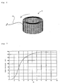
- the filter/coolant 4 in the present embodiment is shown in Fig. 2.
- This filter/coolant 4 is formed in such a manner that one wire 12 made of SUS is wound on a cylindrical member having an outer diameter corresponding to an inner diameter of a filter, and that closed portions and opening portions are obtained by forming portions where the wire crosses and portions where the wire does not cross. Further, the wire is wounded to be laminated and then sintered, thereby forming the filter/coolant 4 provided with an inner space.
- small orifices openings
- solid products such as residues easily clog the orifices.
- This filter/coolant 4 has a function to collect/adhere a solid by-product such as a solid product generated by combustion of the gas generating agent 3. Therefore, when the filter/coolant 4 purifies the activation gas generated due to combustion of the gas generating agent 3 after actuation of the gas generator, the openings (nozzles) are clogged with the solid product to be narrowed so that the pressure loss increases according to the elapse of time. As a result, the pressure (combustion pressure) in the housing 1 after actuation of the gas generator is adjusted by the filter/coolant 4, so that it is possible to avoid deteriorating combustion performance due to decrease of the surface area of the gas generating agent 3.
- an inner cylindrical member 6 provided with a plurality of flame-transferring holes 5 in a circumferential direction is arranged in the housing 1, and an ignition means accommodating chamber 7 accommodating the ignition means 2 and a combustion chamber 8 accommodating the gas generating agent 3 are defined inside of the inner cylindrical member 6 and outside thereof, respectively.
- the ignition means 2 in the present embodiment comprises an electric ignition type igniter 9 which is to be activated by an electric signal and a transfer charge 10 which is to be ignited/burnt by the igniter to eject the flame from flame-transferring holes to ignite/burn the gas generating agents 3.
- a pellet shaped gas generating agent 3 (having a diameter of 5 mm and a thickness of 2 mm) is used as the gas generating agent accommodated in the combustion chamber 8.
- the gas generating agent 3 in such a shape is used in the gas generator of the present invention because, even when the surface area of the gas generating agent 3 is reduced by combustion, the internal pressure in the housing 1 can be adjusted by the openings of the filter/coolant 4 to generate a sufficient amount of activation gas.
- the filter/coolant 4 for purifying/cooling the activation gas is arranged oppositely to a peripheral wall of the housing 1 with a distance in the radial outside of the combustion chamber storing the gas generating agent 3.
- a space defined between an inner wall surface of the housing 1 and an outer periphery of the filter/coolant 4 functions as a flowpath for the activation gas. Since the filter/coolant 4 in the present embodiment has to purify and cool an activation gas, a filter/coolant manufactured by laminating a wire material into multiple layers and sintering them is used.
- any means which collects/adheres the solid by-product generated by combustion of the gas generating agent 3 to increase its pressure loss, can be used properly.
- Whether or not the openings of the filter/coolant 4 are narrowed according to combustion of the gas generating agent 3 can be judged on the basis of a change in the pressure loss of the filter/coolant 4.
- such an adjustment has been made that the pressure loss of the filter/coolant 4 before the gas generating agent 3 burns (before generation of the activation gas) is 0.4 kPa under the atmosphere of 20°C at an air flow rate of 350 liters/minute, and the pressure loss after actuation of the gas generator (that is, after the activation gas generated by combustion of the gas generating agent 3 is purified) is increased to about 1,000% of the former pressure loss.
- the change in pressure loss of the filter/coolant 4 before and after combustion of the gas generating agent 3 is affected by an amount of a solid by-product generated by combustion of the gas generating agent 3, the size thereof and the like.
- any combination of both can be used.
- the gas discharge port 11 formed in the housing 1 is adjusted such that its total area of the opening portions is 90 mm 2 , and the pressure loss is adjusted to 2.5 to 3.5 kPa under the atmosphere of 20°C at an air flow rate of 350 liters/minute. That is, in the gas generator shown in the present embodiment, since the gas discharge port 11 is larger in pressure loss than the filter/coolant 4 at the initial stage of actuation of the gas generator, the pressure (combustion pressure) in the housing 1 is adjusted by the gas discharge port 11. Thereafter, at a time when the pressure loss of the filter/coolant 4 becomes larger than the pressure loss of the gas discharge port 11, the pressure (combustion pressure) in the housing 1 is adjusted by the filter/coolant 4 (actually, its openings).
- the pressure loss (ventilation loss) of an orifice member (the filter/coolant 4 in the present embodiment) before actuation of the gas generator is adjusted to be smaller than the pressure loss (ventilation loss) of the gas discharge port 11 provided in the housing 1.
- the transfer charge 10 when the transfer charge 10 is ignited and burnt by activation of the igniter 9, a flame thereof is ejected from the flame-transferring holes 5 into the combustion chamber 8 to ignite/burn the gas generating agent 3 and to generate an activation gas for inflating the air bag and a solid by-product.
- the solid by-product is removed while passing through the filter/coolant 4, and only the activation gas is cooled by the filter/coolant 4 to be discharged from the gas discharge port 11.
- the solid by-product generated by combustion of the gas generating agent 3 is arrested so that a passing-through area for the activation gas decreases gradually after the combustion of the gas generating agent 3. Thereby, a sufficient pressure for combustion of the gas generating agent 3 is maintained in the combustion chamber.
- the gas generating agent 3 can generate a sufficient amount of an activation gas without deteriorating combustion performance even when its surface area decreases due to combustion.
- Fig. 3 shows a tank curve which has been obtained by conducting a tank combustion test using the gas generator shown in Fig. 1.
- the gas generator there can be realized a gas generator in which an operation performance is adjusted such that the tank internal pressure in the tank combustion test is 50 kPa or less at 15 milliseconds after an ignition current is applied, 140 to 200 kPa at 40 milliseconds after an ignition current is applied, and the peak of the tank internal pressure appears at 60 to 100 milliseconds after the ignition current is applied, and the tank internal pressure at the time of the peak is 230 kPa or less.
- the above-described gas generator for an air bag is accommodated in a module case together with an air bag (bag body) which introduces therein a gas generated by the gas generator to inflate, thereby forming an air bag apparatus.
- the gas generator is actuated, reacting upon the impact sensor detecting the impact, and then discharge a combustion gas from the gas discharge port of the housing.
- the combustion gas flows into the air bag, and thereby an air bag breaks a module cover to inflate and form a cushion absorbing an impact between a hard structure in the vehicle and an occupant.
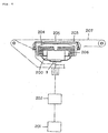
- Fig. 4 shows an embodiment of an air bag apparatus according to the present invention, including a gas generator in which the electric ignition type ignition means is used.
- the air bag apparatus comprises a gas generator 200, an impact sensor 201, a control unit 202, a module case 203 and an air bag 204.
- the gas generator 200 the gas generator described with reference to Fig. 1 is used, and the operation performance thereof is adjusted to apply as a small impact as possible to the occupant at the initial stage of the actuation of the gas generator.
- the impact sensor 201 can comprise, for example, a semiconductor type acceleration sensor.
- the semiconductor type acceleration sensor is structured such that four semiconductor strain gauges are formed on a beam of a silicone base plate to be deflected when the acceleration is applied, and these semiconductor strain gauges are bridge-connected. When the acceleration is applied, the beam deflects and a stain is produced on the surface. Due to the strain, a resistance of the semiconductor strain gauge is changed, and the structure is made such that the resistance change can be detected as a voltage signal in proportion to the acceleration.
- the control unit 202 is provided with an ignition decision circuit, and the signal from the semiconductor type acceleration sensor is inputted to the ignition decision circuit.
- the control unit 202 starts calculation at a time when the impact signal from the sensor 201 exceeds a certain value, and when the calculated result exceeds a certain value, it outputs the activation signal to the igniter 9 of the gas generator 200.
- the module case 203 is formed, for example, by a polyurethane, and includes a module cover 205.
- the air bag 204 and the gas generator 200 are stored in the module case 203 so as to be constituted as a pad module.
- the pad module is generally mounted to a steering wheel 207 when being mounted to a driver side of an automobile.
- the air bag 204 is formed of a nylon (for example, a nylon 66), a polyester or the like, and a bag port 206 thereof surrounds the gas discharge port of the gas generator and is fixed to a flange portion of the gas generator in a folded state.
- a nylon for example, a nylon 66
- the semiconductor type acceleration sensor 201 senses the impact at a time of collision of the automobile, the signal is transmitted to the control unit 202, and the control unit 202 starts calculation at a time when the impact signal from the sensor exceeds a certain value.
- the calculated result exceeds a certain value, it outputs the activating signal to the igniter 9 of the gas generator 200.
- the igniter 4 is activated so as to ignite the gas generating agent, and the gas generating agent burns and generates a gas.
- the gas is ejected into the air bag 204, whereby the air bag breaks the module cover 205 so as to inflate, forming a cushion absorbing an impact between the steering wheel 207 and the occupant.
Landscapes
- Engineering & Computer Science (AREA)
- Mechanical Engineering (AREA)
- Physics & Mathematics (AREA)
- Fluid Mechanics (AREA)
- Air Bags (AREA)
Abstract
The present invention provides a gas generator for an air
bag which has a simple structure and is capable of inflating
an air bag at an optimal timing and at an optimal developing
speed from the time when a gas generator starts actuating.
There is provided a gas generator for an air bag in which
a gas generating means is stored in a combustion chamber defined
in a housing, an orifice member having a plurality of nozzles
which are narrowed according to combustion of the gas generating
means is provided in a flow path for an activation gas extending
from the combustion chamber to a gas discharge port, and a proper
combustion pressure is maintained by the orifice member.
Description
The present invention relates to a gas generator for an
air bag for protecting a vehicle occupant from the impact,
particularly, to a gas generator for an air bag characterized
in its operation performance, and an air bag apparatus using
the gas generator.
In a vehicle such as an automobile, in order to prevent
the passenger from crashing into a hard portion inside the
vehicle such as a steering wheel and a windshield due to an
inertia and being injured or died when the vehicle collides at
a high speed, an air bag system, which inflates an air bag rapidly
with a gas to protect a passenger from colliding against a
dangerous portion of the vehicle, is provided.
It is demanded that such an air bag system can safely
restrain the passenger even when the frame of the occupant (for
example, whether a sitting height is long or short, whether an
adult or a child, and the like), a sitting attitude (for example,
an attitude of holding on the steering wheel) and the like are
different. Then, there has been conventionally suggested an
air bag system which is actuated, applying the impact to the
passenger as small as possible at the initial stage of the
actuation.
JP-A 8-207696 suggests using two kinds of gas generating
agent capsules for generating a gas at two stages comprising
a first stage in which an air bag is inflated relatively slowly
and a second stage in which a gas is generated rapidly. However,
in this art, there is a drawback such that the structure of the
interior of the gas generator is complicated and the size of
a container is made large, which results in a factor of
increasing the cost.
Also in US-A 4,998,751 and US-A 4,950,458, it is proposed
that two combustion chambers are provided for restricting the
actuation function of the gas generator and the gas generating
agent is burnt at two stages. The structure is, however,
complicated and it is not satisfactory.
The present invention provides a gas generator for an air
bag which has a simple structure and can inflate an air bag at
an optimal timing from a start of actuation of a gas generator
and at an optimal developing speed.
The above object of the present invention can be achieved
by a gas generator for an air bag comprising, in a housing having
a gas discharge port, an ignition means which actuates a gas
generator and a gas generating means which generates an
activation gas for inflating an air bag due to the actuation
of the ignition means, wherein the gas generating means is
accommodated in a combustion chamber, an orifice member
provided with a plurality of nozzles which are narrowed
according to combustion of the gas generating means is provided
in a flow path for the activation gas extending from the
combustion chamber to the gas discharge port, and a proper
combustion pressure is maintained by the orifice member.
For example, if a solid product such as a combustion
residue generated by combustion of the gas generating means
clogs in the nozzles of the orifice member provided in the flow
path for the activation gas to narrow them, the combustion
pressure can be maintained by the stepwise clogged nozzles.
That is, the gas generating means burns to reduce its surface
area, and thereby the combustion performance of the gas
generating means is lowered. However, by arranging such an
orifice member in the flow path of an activation gas, the
combustion pressure can be maintained properly, so that
compensation is made for lowering of the combustion performance
of the gas generating means and the combustion performance of
the gas generating means can be adjusted.
Whether or not the nozzles of the orifice member are
narrowed according to the combustion of the gas generating means
is judged on the basis of the change of the pressure loss of
the orifice member. That is, the pressure loss (or ventilation
resistance) of the orifice member before the gas generating
means burns (before an activation gas is generated) is measured
and the pressure loss (or ventilation resistance) of the orifice
member after the gas generator is actuated (after the activation
gas is purified) is measured, and when the latter pressure loss
(or ventilation resistance) is increased compared with the
former, it can be judged that the nozzles of the orifice member
are narrowed according to the combustion of the gas generating
means. In the present invention, an orifice member constituted
such that the pressure loss (ventilation resistance) of the
orifice member after actuation of the gas generator is 300% or
more of the pressure loss (ventilation resistance) of the
orifice member before the actuation of the gas generator is
preferably used.
If the orifice member is judged by the pressure loss in
this manner, it is preferable that the orifice member of the
present invention is adjusted such that its pressure loss is
smaller than that of the gas discharge port before combustion
of the gas generating means and is larger than that of the gas
discharge port after the combustion of the gas generating means.
The orifice member which is narrowed by clogging the
nozzles with a solid product generated according to combustion
of the gas generating means is judged on the basis of a
correlation between the pressure loss before combustion of the
gas generating means and the amount of the solid product
generated from the gas generating means. As the orifice member
in the present invention, such one is preferably used that its
pressure loss before and after actuation of the gas generator
is increased 300% or more, more preferably, 500 to 1,500%,
further preferably, 800 to 1,000% or so. Such an orifice member
can be realized by, for example, a combination of an orifice
member having the pressure loss of 0.4 to 0.8 kPa under the
atmosphere of 20°C at a flow rate of air of 350 liters/minute
and the gas generating means which generates a solid product
of 15g per 100g of the gas generating means, preferably, a solid
product of 30g.
As the above-described orifice member, for example, a
filter means can be used. In this case, openings of the filter
means serve as the nozzles. Such a filter means is disposed
inside the housing in order to remove the solid product
generated by combustion of the gas generating means. As such
a filter means, a filter which is used for purifying an
activation gas generated by combustion of the gas generating
means, a coolant which is used for removing the solid product
contained in an activation gas, and a coolant/filter which has
both the functions can be used. Also, as such a filter means,
one which is formed by winding a metal wire mesh in a laminating
manner or one which is formed by winding an expanded metal in
a multi-layer can be used.
When the filter means is used as the orifice member, the
term "pressure loss" means a pressure loss in the radial
direction of the filter means. The pressure loss of the filter
means and the pressure loss of the gas discharge port can be
obtained by a difference between the pressure in an gas-inflow
side and the pressure in gas-outflow side. If the openings of
the filter means correspond to the nozzles in the orifice member,
whether or not the openings in the filter means are narrowed
according to combustion of the gas generating means can be
regarded as change of the pressure loss of the filter means
itself. That is, the pressure loss of the filter means before
the gas generating means burns (before generation of the
activation gas) is measured, the pressure loss of the filter
means after actuation of the gas generator (after purifying of
an activation gas) is then measured, and when the pressure loss
of the latter has been increased, it can be determined that the
openings of the filter means are narrowed according to
combustion of the gas generating means. In the present
invention, a filter means structured such that the pressure loss
of the filter means after actuation of the gas generator reaches
300% or more of the pressure loss of the filter means before
actuation of the gas generator is preferably used.
As the gas generating means, a conventional gas
generating means which generates an activation gas for
inflating an air bag by combustion can be used. As such a gas
generating means, a conventionally and widely used azide type
gas generating means based on an inorganic azide such as a sodium
azide or the like, or so-called non-azide type gas generating
means which is not based on the inorganic azide may be used.
When the orifice member is which the nozzles are narrowed by
the solid product generated by combustion of the gas generating
means is used, a gas generating means generating a solid product
in a proper amount is preferably used. Such a gas generating
means can include, for example, a tetrazole compound such as
5-amino tetrazole or the like, guanidine derivatives such as
nitroguanidine, metal nitrate such as strontium nitrate or the
like, and material including natural clay, talc, clay, silica
or binder, if required. Further in the present invention, as
the gas generating means, one whose surface area is remarkably
reduced by combustion, for example, a gas generating means
formed in a tablet shape, can be used. This is because, even
if the surface area of the gas generating means becomes small
according to combustion thereof, the internal pressure of the
housing is sufficiently adjusted so that a sufficient amount
of gas discharge can be secured without reduction of the
combustion performance, as described above.
The ignition means is disposed inside the housing to
actuate the gas generator for an air bag by igniting and burning
the gas generating means, and a known electric ignition type
igniter or mechanical ignition type igniter, or one obtained
by combining these igniters and a transfer charge can be used
as the ignition means.
Also, the present invention provides a gas generator for
an air bag comprising, in a housing having a gas discharge port,
an ignition means to actuate a gas generator and a gas generating
means which generates an activation gas for inflating an air
bag due to actuation of the ignition means, wherein the
operation performance of the gas generator is adjusted such that
a tank internal pressure in a tank combustion test is 50 kPa
or less at 15 milliseconds after an igniting current is applied,
140 to 200 kPa at 40 milliseconds after the igniting current
is applied, and the peak of the internal pressure of the tank
appears at 60 to 100 milliseconds after the igniting current
is applied, and that the tank internal pressure at that time
(peak time) becomes 230 kPa or less.
In the gas generator, by setting the tank internal
pressure at 15 milliseconds after an igniting current is applied
to 50 kPa or less, a safe activation can be achieved even at
the initial stage of actuation of the gas generator, and by
setting the tank internal pressure at 40 milliseconds after the
igniting current is applied to 40 to 200 kPa, a sufficient
restraining force can be obtained. Further, if such an
adjustment is made that the peak of the tank internal pressure
appears at 60 to 100 milliseconds after the igniting current
is applied and that the tank internal pressure at that time (peak
time) becomes 230 kPa or less, a passenger can be supported with
a proper force while maintaining a restraining force of the air
bag. If the pressure is too strong at the peak time, the
occupant once restrained may be pushed aside, and a satisfactory
operation performance can not be expected.
In the gas generator of the present invention showing such
an operation performance, since the gas discharge amount is
maintained after activation, particularly in the latter half
of combustion of the gas generating means, an air bag (bag body)
accommodated in a module can be developed without imparting an
excessive impact to a vehicle occupant while maintaining an
inflating speed of the initial stage.
The tank combustion test in the present invention is a
test conducted in a method described below. The tank internal
pressure is a pressure inside a tank made of SUS in the tank
combustion test. A value of the tank internal pressure
ordinarily varies according to time elapse.
A gas generator for an air bag is fixed inside a tank made
of SUS (stainless steel) and having an internal volume of 60
liters, and it is connected to an external igniting electric
circuit after the tank is sealed at the room temperature. A
time when a switch of the igniting electric circuit is turned
on (when igniting current is applied) is set to 0 and a pressure
increase change in the tank is measured for 0 to 200 milliseconds
by a pressure transducer separately provided to the tank. A
curve (hereinafter, referred to as "tank curve") for evaluating
the performance of the gas generator can be finally obtained
as a tank pressure/time curve by performing computer processing
on respective measurement data. A portion of the gas in the
tank is taken out after completion of the combustion and it can
be provided for a gas analysis of such a gas as CO, NOx.
Also, the combustion pressure in the present invention
means a pressure in the housing obtained by combustion of the
gas generating means at the tank combustion test, and, naturally,
the value thereof varies according to time elapse. The peak
of the combustion maximum internal pressure in the housing means
the time when the housing internal pressure becomes the maximum
due to combustion of the gas generating means after the igniting
current is applied. After the igniting current is applied, this
housing internal pressure ascends until a seal tape closing the
gas discharge port is ruptured, and it descends once after the
seal tape is ruptured. The peak of the combustion maximum
internal pressure in the present invention means the time when
the housing internal pressure ascends by combustion of the gas
generating means and reach the maximum after the seal tape
closing the gas discharge port is ruptured. Even if the housing
internal pressure becomes the maximum at the time when the seal
tape is ruptured, the time is not included in the peak.
In the above-described gas generator of the present
invention, of course, it is possible to properly select/adopt
an advantageous structure or part such as, for example, a
cushion member supporting a gas generating means to prevent
cracking into pieces due to vibrations, within a range where
the effect of the invention is not deteriorated.
The above-described gas generator for an air bag of the
present invention can be constituted as an air bag apparatus
including an impact sensor detecting the impact to actuate the
gas generator, an air bag to introduce a gas generated by the
gas generator to inflate, and a module case accommodating the
air bag. The gas generator is accommodated in the module case
together with the air bag (bag body) to introduce the gas
generated to inflate, thereby being provided as a pad module.
When the gas generator is provided with an electric ignition
type igniter activated by the electric signal, the pad module
is combined with an impact sensor detecting the impact and a
control unit outputting an activation signal to the gas
generator upon the signal inputted from the impact sensor, thus.
forming an air bag apparatus.
In the air bag apparatus, the gas generator is actuated
upon the impact sensor detecting the impact to discharge a
combustion gas from the gas discharge port of the housing. The
combustion gas flows into the air bag, and thereby the air bag
breaks a module cover to inflate and forms a cushion absorbing
the impact between a hard structure in the vehicle and an
occupant.
The present invention can provide a gas generator for an
air bag having a simple structure, and it can also provide a
gas generator which adjusts the internal pressure in the gas
generator according to combustion of the gas generating means
to maintain a proper combustion generally during the
combustion.
A gas generator for an air bag of the present invention
provided with the above-described performances can be realized
in the embodiments described below.
Fig. 1 is a vertical cross sectional view of one
embodiment in a gas generator for an air bag of the present
invention. A gas generator shown in this figure is formed so
as to include and accommodate, in a housing 1 having a gas
discharge port, an ignition means 2 and a gas generating agent
3 which generates an activation gas for inflating an air bag
by actuation of the ignition means 2. Further, a filter means
for removing a solid product generated by combustion of the gas
generating agent 3, that is, a filter/coolant 4 for purifying
and cooling the activation gas in the present embodiment, is
arranged between a combustion chamber storing the gas
generating agent 3 and the housing 1 as an orifice member. This
filter/coolant 4 functions as the orifice member and its
openings function as nozzles which are narrowed according to
combustion of the gas generating agent 3.
The filter/coolant 4 in the present embodiment is shown
in Fig. 2. This filter/coolant 4 is formed in such a manner
that one wire 12 made of SUS is wound on a cylindrical member
having an outer diameter corresponding to an inner diameter of
a filter, and that closed portions and opening portions are
obtained by forming portions where the wire crosses and portions
where the wire does not cross. Further, the wire is wounded
to be laminated and then sintered, thereby forming the
filter/coolant 4 provided with an inner space. In the
filter/coolant 4 obtained in this manner, since small orifices
(openings) are arranged uniformly and orifices are continuously
arranged, solid products such as residues easily clog the
orifices.
This filter/coolant 4 has a function to collect/adhere
a solid by-product such as a solid product generated by
combustion of the gas generating agent 3. Therefore, when the
filter/coolant 4 purifies the activation gas generated due to
combustion of the gas generating agent 3 after actuation of the
gas generator, the openings (nozzles) are clogged with the solid
product to be narrowed so that the pressure loss increases
according to the elapse of time. As a result, the pressure
(combustion pressure) in the housing 1 after actuation of the
gas generator is adjusted by the filter/coolant 4, so that it
is possible to avoid deteriorating combustion performance due
to decrease of the surface area of the gas generating agent 3.
In Fig. 1, an inner cylindrical member 6 provided with
a plurality of flame-transferring holes 5 in a circumferential
direction is arranged in the housing 1, and an ignition means
accommodating chamber 7 accommodating the ignition means 2 and
a combustion chamber 8 accommodating the gas generating agent
3 are defined inside of the inner cylindrical member 6 and
outside thereof, respectively. The ignition means 2 in the
present embodiment comprises an electric ignition type igniter
9 which is to be activated by an electric signal and a transfer
charge 10 which is to be ignited/burnt by the igniter to eject
the flame from flame-transferring holes to ignite/burn the gas
generating agents 3. Particularly in the present embodiment,
a pellet shaped gas generating agent 3 (having a diameter of
5 mm and a thickness of 2 mm) is used as the gas generating agent
accommodated in the combustion chamber 8. The gas generating
agent 3 in such a shape is used in the gas generator of the present
invention because, even when the surface area of the gas
generating agent 3 is reduced by combustion, the internal
pressure in the housing 1 can be adjusted by the openings of
the filter/coolant 4 to generate a sufficient amount of
activation gas. As the gas generating agent 3 in the present
embodiment, a gas generating agent 3 comprising
nitroguanidine/strontium nitrate/sodium salt of
carboxymethylcellulose/acid clay = 34.4/49.5/9.4/6.7
(weight %) is used in an amount of 40g, and it generates a solid
product of about 12g by combustion thereof.
The filter/coolant 4 for purifying/cooling the
activation gas is arranged oppositely to a peripheral wall of
the housing 1 with a distance in the radial outside of the
combustion chamber storing the gas generating agent 3. A space
defined between an inner wall surface of the housing 1 and an
outer periphery of the filter/coolant 4 functions as a flowpath
for the activation gas. Since the filter/coolant 4 in the
present embodiment has to purify and cool an activation gas,
a filter/coolant manufactured by laminating a wire material
into multiple layers and sintering them is used. However, as
the filter means in the present invention, any means, which
collects/adheres the solid by-product generated by combustion
of the gas generating agent 3 to increase its pressure loss,
can be used properly.
Whether or not the openings of the filter/coolant 4 are
narrowed according to combustion of the gas generating agent
3 can be judged on the basis of a change in the pressure loss
of the filter/coolant 4. In the present embodiment, such an
adjustment has been made that the pressure loss of the
filter/coolant 4 before the gas generating agent 3 burns (before
generation of the activation gas) is 0.4 kPa under the
atmosphere of 20°C at an air flow rate of 350 liters/minute,
and the pressure loss after actuation of the gas generator (that
is, after the activation gas generated by combustion of the gas
generating agent 3 is purified) is increased to about 1,000%
of the former pressure loss.
The change in pressure loss of the filter/coolant 4 before
and after combustion of the gas generating agent 3 is affected
by an amount of a solid by-product generated by combustion of
the gas generating agent 3, the size thereof and the like. In
the present invention, however, as long as the above-described
degree of pressure loss can be achieved in the relationship
between the filter/coolant 4 and the generated amount/size of
the solid product of the gas generating agent 3 or the like,
any combination of both can be used.
The gas discharge port 11 formed in the housing 1 is
adjusted such that its total area of the opening portions is
90 mm2, and the pressure loss is adjusted to 2.5 to 3.5 kPa under
the atmosphere of 20°C at an air flow rate of 350 liters/minute.
That is, in the gas generator shown in the present embodiment,
since the gas discharge port 11 is larger in pressure loss than
the filter/coolant 4 at the initial stage of actuation of the
gas generator, the pressure (combustion pressure) in the
housing 1 is adjusted by the gas discharge port 11. Thereafter,
at a time when the pressure loss of the filter/coolant 4 becomes
larger than the pressure loss of the gas discharge port 11, the
pressure (combustion pressure) in the housing 1 is adjusted by
the filter/coolant 4 (actually, its openings). Thus, in case
that the internal pressure in the housing 1 is adjusted by the
gas discharge port 11 at the initial stage of actuation of the
gas generator, it is required that the pressure loss
(ventilation loss) of an orifice member (the filter/coolant 4
in the present embodiment) before actuation of the gas generator
is adjusted to be smaller than the pressure loss (ventilation
loss) of the gas discharge port 11 provided in the housing 1.
In the gas generator of the present embodiment, when the
transfer charge 10 is ignited and burnt by activation of the
igniter 9, a flame thereof is ejected from the flame-transferring
holes 5 into the combustion chamber 8 to
ignite/burn the gas generating agent 3 and to generate an
activation gas for inflating the air bag and a solid by-product.
The solid by-product is removed while passing through the
filter/coolant 4, and only the activation gas is cooled by the
filter/coolant 4 to be discharged from the gas discharge port
11. In the filter/coolant 4, the solid by-product generated
by combustion of the gas generating agent 3 is arrested so that
a passing-through area for the activation gas decreases
gradually after the combustion of the gas generating agent 3.
Thereby, a sufficient pressure for combustion of the gas
generating agent 3 is maintained in the combustion chamber. As
a result, the gas generating agent 3 can generate a sufficient
amount of an activation gas without deteriorating combustion
performance even when its surface area decreases due to
combustion.
Fig. 3 shows a tank curve which has been obtained by
conducting a tank combustion test using the gas generator shown
in Fig. 1.
Accordingly, according to the gas generator, there can
be realized a gas generator in which an operation performance
is adjusted such that the tank internal pressure in the tank
combustion test is 50 kPa or less at 15 milliseconds after an
ignition current is applied, 140 to 200 kPa at 40 milliseconds
after an ignition current is applied, and the peak of the tank
internal pressure appears at 60 to 100 milliseconds after the
ignition current is applied, and the tank internal pressure at
the time of the peak is 230 kPa or less.
The above-described gas generator for an air bag is
accommodated in a module case together with an air bag (bag body)
which introduces therein a gas generated by the gas generator
to inflate, thereby forming an air bag apparatus.
In this air bag apparatus, the gas generator is actuated,
reacting upon the impact sensor detecting the impact, and then
discharge a combustion gas from the gas discharge port of the
housing. The combustion gas flows into the air bag, and thereby
an air bag breaks a module cover to inflate and form a cushion
absorbing an impact between a hard structure in the vehicle and
an occupant.
Fig. 4 shows an embodiment of an air bag apparatus
according to the present invention, including a gas generator
in which the electric ignition type ignition means is used.
The air bag apparatus comprises a gas generator 200, an
impact sensor 201, a control unit 202, a module case 203 and
an air bag 204. As the gas generator 200, the gas generator
described with reference to Fig. 1 is used, and the operation
performance thereof is adjusted to apply as a small impact as
possible to the occupant at the initial stage of the actuation
of the gas generator.
The impact sensor 201 can comprise, for example, a
semiconductor type acceleration sensor. The semiconductor
type acceleration sensor is structured such that four
semiconductor strain gauges are formed on a beam of a silicone
base plate to be deflected when the acceleration is applied,
and these semiconductor strain gauges are bridge-connected.
When the acceleration is applied, the beam deflects and a stain
is produced on the surface. Due to the strain, a resistance
of the semiconductor strain gauge is changed, and the structure
is made such that the resistance change can be detected as a
voltage signal in proportion to the acceleration.
The control unit 202 is provided with an ignition decision
circuit, and the signal from the semiconductor type
acceleration sensor is inputted to the ignition decision
circuit. The control unit 202 starts calculation at a time when
the impact signal from the sensor 201 exceeds a certain value,
and when the calculated result exceeds a certain value, it
outputs the activation signal to the igniter 9 of the gas
generator 200.
The module case 203 is formed, for example, by a
polyurethane, and includes a module cover 205. The air bag 204
and the gas generator 200 are stored in the module case 203 so
as to be constituted as a pad module. The pad module is
generally mounted to a steering wheel 207 when being mounted
to a driver side of an automobile.
The air bag 204 is formed of a nylon (for example, a nylon
66), a polyester or the like, and a bag port 206 thereof surrounds
the gas discharge port of the gas generator and is fixed to a
flange portion of the gas generator in a folded state.
When the semiconductor type acceleration sensor 201
senses the impact at a time of collision of the automobile, the
signal is transmitted to the control unit 202, and the control
unit 202 starts calculation at a time when the impact signal
from the sensor exceeds a certain value. When the calculated
result exceeds a certain value, it outputs the activating signal
to the igniter 9 of the gas generator 200. Accordingly, the
igniter 4 is activated so as to ignite the gas generating agent,
and the gas generating agent burns and generates a gas. The
gas is ejected into the air bag 204, whereby the air bag breaks
the module cover 205 so as to inflate, forming a cushion
absorbing an impact between the steering wheel 207 and the
occupant.
Claims (8)
- A gas generator for an air bag, comprising, in a housing having a gas discharge port, an ignition means which actuates a gas generator and a gas generating means which generates an activation gas for inflating an air bag by the actuation of the ignition means,
wherein the gas generating means is accommodated in a combustion chamber, an orifice member provided with a plurality of nozzles which are narrowed according to combustion of the gas generating means is provided in a flow path for an activation gas extending from the combustion chamber to the gas discharge port, and a proper combustion pressure is maintained by the orifice member. - A gas generator for an air bag, comprising, in a housing having a gas discharge port, an ignition means which actuates a gas generator and a gas generating means which generates an activation gas for inflating an air bag by the actuation of the ignition means,
wherein the gas generating means is accommodated in a combustion chamber, an orifice member provided with a plurality of nozzles which are narrowed according to combustion of the gas generating means is provided in a flow path for an activation gas extending from the combustion chamber to the gas discharge port, and the nozzles are clogged with a solid product generated by the combustion of the gas generating means and narrowed, so that a proper combustion pressure is maintained. - A gas generator for an air bag according to claim 1 or 2, wherein, in the orifice member, a pressure loss thereof is smaller than the pressure loss of the gas discharge port before combustion of the gas generating means and is larger than the pressure loss of the gas discharge port after combustion of the gas generating means.
- A gas generator for an air bag according to any one of claims 1 to 3, wherein a filter means for removing a solid product generated by combustion of the gas generating means is disposed in the housing, and the orifice means is the filter means, and the nozzles are openings of the filter means.
- A gas generator for an air bag according to any one of claims 1 to 4, wherein the orifice member provided in the flow path for an activation gas compensates for lowering of the combustion performance of the gas generating means due to that the gas generating means burns and the surface area thereof decreases, and the orifice member adjusts the combustion performance of the gas generating means.
- A gas generator for an air bag according to any one of claims 1 to 5, wherein the operation performance of the gas generator is adjusted such that a tank internal pressure in a tank combustion test is 50 kPa or less at 15 milliseconds after an ignition current is applied, is 140 to 200 kPa at 40 milliseconds after the ignition current is applied, and the peak of the tank internal pressure appears at 60 to 100 milliseconds after the ignition current is applied, and the tank internal pressure at the time of the peak is 230 kPa or less.
- A gas generator for an air bag, comprising, in a housing having a gas discharge port, an ignition means which actuates a gas generator and a gas generating means which generates an activation gas for inflating an air bag by the actuation of the ignition means,
wherein the operation performance of the gas generator is adjusted such that a tank internal pressure in a tank combustion test is 50 kPa or less at 15 milliseconds after an ignition current is applied, is 140 to 200 kPa at 40 milliseconds after the ignition current is applied, and the peak of the tank internal pressure appears at 60 to 100 milliseconds after the ignition current is applied, and the tank internal pressure at the time of the peak is 230 kPa or less. - An air bag apparatus comprising:a gas generator for an air bag;an impact sensor which actuates the gas generator upon detecting the impact;an air bag which introduces a gas generated by the gas generator to inflate; anda module case which stores the air bag, wherein the gas generator for an air bag is a gas generator of an air bag according to any one of claims 1 to 7.
Applications Claiming Priority (3)
| Application Number | Priority Date | Filing Date | Title |
|---|---|---|---|
| JP37006199A JP2001180428A (en) | 1999-12-27 | 1999-12-27 | Gas generator and airbag device for airbag |
| JP37006199 | 1999-12-27 | ||
| PCT/JP2000/009325 WO2001047753A1 (en) | 1999-12-27 | 2000-12-27 | Gas generator for air bag and air bag device |
Publications (2)
| Publication Number | Publication Date |
|---|---|
| EP1243484A1 true EP1243484A1 (en) | 2002-09-25 |
| EP1243484A4 EP1243484A4 (en) | 2005-01-19 |
Family
ID=18495981
Family Applications (1)
| Application Number | Title | Priority Date | Filing Date |
|---|---|---|---|
| EP00985952A Withdrawn EP1243484A4 (en) | 1999-12-27 | 2000-12-27 | GAS GENERATOR FOR AIR BAGS AND AIR BAG DEVICE |
Country Status (7)
| Country | Link |
|---|---|
| US (1) | US20030057687A1 (en) |
| EP (1) | EP1243484A4 (en) |
| JP (1) | JP2001180428A (en) |
| KR (1) | KR20020065613A (en) |
| CN (1) | CN1413153A (en) |
| TW (1) | TW512108B (en) |
| WO (1) | WO2001047753A1 (en) |
Families Citing this family (9)
| Publication number | Priority date | Publication date | Assignee | Title |
|---|---|---|---|---|
| US7150470B2 (en) * | 2002-05-31 | 2006-12-19 | Toyoda Gosei Co., Ltd. | Airbag device for front passenger's seat |
| JP4532124B2 (en) * | 2004-01-07 | 2010-08-25 | ダイセル化学工業株式会社 | Airbag gas generator filter |
| JP4691450B2 (en) * | 2004-02-10 | 2011-06-01 | 中央発條株式会社 | Filtration member and manufacturing method thereof |
| FR2876968B1 (en) * | 2004-10-26 | 2007-01-12 | Livbag Soc Par Actions Simplif | GAS GENERATOR EQUIPPED WITH PRESSURE CONTROL MEANS AND SAFETY DEVICE PROVIDED THEREIN. |
| US8328234B2 (en) * | 2008-10-30 | 2012-12-11 | Autoliv Asp, Inc. | Airbag inflator |
| JP5324930B2 (en) * | 2009-01-15 | 2013-10-23 | 株式会社ダイセル | Gas generator for vehicle restraint system |
| JP5638996B2 (en) * | 2011-03-30 | 2014-12-10 | 株式会社ダイセル | Gas generator for personnel restraint system |
| FR3053456B1 (en) * | 2016-06-29 | 2018-06-29 | Autoliv Development Ab | GAS GENERATOR |
| CN108589795B (en) * | 2018-04-10 | 2020-09-15 | 同济大学 | A ground wall bayonet airbag type quick plugging device |
Family Cites Families (6)
| Publication number | Priority date | Publication date | Assignee | Title |
|---|---|---|---|---|
| KR0121801B1 (en) * | 1993-09-17 | 1997-11-25 | 제럴드 켄트 화이트 | Hybrid gas generator and production of expansion gas |
| US6234521B1 (en) * | 1996-04-08 | 2001-05-22 | Daicel Chemical Industries, Ltd. | Airbag inflator and an airbag apparatus |
| JPH1059115A (en) * | 1996-05-24 | 1998-03-03 | Nippon Koki Co Ltd | Gas generator for airbag |
| JP2926040B2 (en) * | 1997-05-09 | 1999-07-28 | ダイセル化学工業株式会社 | Gas generator and airbag device for airbag |
| JPH1191495A (en) * | 1997-09-18 | 1999-04-06 | Nippon Kayaku Co Ltd | Gas generator |
| KR100417766B1 (en) * | 1999-04-28 | 2004-02-05 | 니뽄 가야쿠 가부시키가이샤 | Gas generator |
-
1999
- 1999-12-27 JP JP37006199A patent/JP2001180428A/en not_active Withdrawn
-
2000
- 2000-12-27 KR KR1020027008294A patent/KR20020065613A/en not_active Withdrawn
- 2000-12-27 WO PCT/JP2000/009325 patent/WO2001047753A1/en not_active Ceased
- 2000-12-27 US US10/169,124 patent/US20030057687A1/en not_active Abandoned
- 2000-12-27 TW TW089127952A patent/TW512108B/en not_active IP Right Cessation
- 2000-12-27 EP EP00985952A patent/EP1243484A4/en not_active Withdrawn
- 2000-12-27 CN CN00817713A patent/CN1413153A/en active Pending
Also Published As
| Publication number | Publication date |
|---|---|
| CN1413153A (en) | 2003-04-23 |
| US20030057687A1 (en) | 2003-03-27 |
| EP1243484A4 (en) | 2005-01-19 |
| JP2001180428A (en) | 2001-07-03 |
| TW512108B (en) | 2002-12-01 |
| KR20020065613A (en) | 2002-08-13 |
| WO2001047753A1 (en) | 2001-07-05 |
Similar Documents
| Publication | Publication Date | Title |
|---|---|---|
| JP2963086B1 (en) | Gas generator and airbag device for airbag | |
| EP1518764B1 (en) | Gas generator for an airbag and air bag apparatus | |
| US6547275B2 (en) | Air bag gas generator and air bag device | |
| EP1074433B1 (en) | An airbag inflator and an airbag apparatus | |
| EP1200288B1 (en) | Variable output airbag inflator | |
| EP1658204B1 (en) | Pyrotechnique side impact inflator | |
| CN101316744A (en) | Inflator dual stage combustion control system | |
| WO2003042010A1 (en) | Gas generator | |
| KR19980080593A (en) | Gas generating pellets, gas generators and airbag devices | |
| EP1243484A1 (en) | Gas generator for air bag and air bag device | |
| JPH10315897A (en) | Coolant/filter for gas generator for air bag | |
| JPH1095302A (en) | Gas generator for air bag and air bag device | |
| JPH1159315A (en) | Cushion member of gas generator for air bag | |
| JP3218213B2 (en) | Gas generator for airbag and airbag device | |
| JPH11348711A (en) | Gas generator for air bag and air bag device | |
| EP1346886B1 (en) | Air bag-use gas generator and air bag device | |
| JP3790669B2 (en) | Gas generator for airbag and airbag device | |
| EP1407944A1 (en) | Gas generator for air bag and air bag device | |
| JP4860809B2 (en) | Gas generator for airbag and airbag device | |
| JP4542698B2 (en) | Gas generator for airbag and airbag device | |
| JP3766643B2 (en) | Gas generator for airbag | |
| JP2002193069A (en) | Gas generator for airbag and airbag device | |
| JPH11189125A (en) | Gas generator for air bag and air bag device | |
| JP2001219811A (en) | Gas generator for air bag and air bag device |
Legal Events
| Date | Code | Title | Description |
|---|---|---|---|
| PUAI | Public reference made under article 153(3) epc to a published international application that has entered the european phase |
Free format text: ORIGINAL CODE: 0009012 |
|
| 17P | Request for examination filed |
Effective date: 20020619 |
|
| AK | Designated contracting states |
Kind code of ref document: A1 Designated state(s): AT BE CH CY DE DK ES FI FR GB GR IE IT LI LU MC NL PT SE TR |
|
| RBV | Designated contracting states (corrected) |
Designated state(s): AT BE CH DE FR GB LI |
|
| A4 | Supplementary search report drawn up and despatched |
Effective date: 20041207 |
|
| STAA | Information on the status of an ep patent application or granted ep patent |
Free format text: STATUS: THE APPLICATION IS DEEMED TO BE WITHDRAWN |
|
| 18D | Application deemed to be withdrawn |
Effective date: 20050222 |