EP1243440A2 - Sheet post-processing device, image forming apparatus having the device and error handling method therefor - Google Patents
Sheet post-processing device, image forming apparatus having the device and error handling method therefor Download PDFInfo
- Publication number
- EP1243440A2 EP1243440A2 EP02005624A EP02005624A EP1243440A2 EP 1243440 A2 EP1243440 A2 EP 1243440A2 EP 02005624 A EP02005624 A EP 02005624A EP 02005624 A EP02005624 A EP 02005624A EP 1243440 A2 EP1243440 A2 EP 1243440A2
- Authority
- EP
- European Patent Office
- Prior art keywords
- sheet
- sheets
- discharge path
- post
- error handling
- Prior art date
- Legal status (The legal status is an assumption and is not a legal conclusion. Google has not performed a legal analysis and makes no representation as to the accuracy of the status listed.)
- Granted
Links
- 238000012805 post-processing Methods 0.000 title claims abstract description 215
- 238000000034 method Methods 0.000 title claims abstract description 39
- 238000012545 processing Methods 0.000 claims description 34
- 238000004891 communication Methods 0.000 claims description 23
- 230000008569 process Effects 0.000 claims description 8
- 238000004080 punching Methods 0.000 claims description 5
- 230000002159 abnormal effect Effects 0.000 claims description 4
- 239000011230 binding agent Substances 0.000 claims 1
- 238000007599 discharging Methods 0.000 description 8
- 238000010586 diagram Methods 0.000 description 7
- 230000007246 mechanism Effects 0.000 description 5
- 230000000694 effects Effects 0.000 description 4
- 239000000463 material Substances 0.000 description 4
- 230000001276 controlling effect Effects 0.000 description 3
- 238000012790 confirmation Methods 0.000 description 2
- 238000001514 detection method Methods 0.000 description 2
- 238000012986 modification Methods 0.000 description 2
- 230000004048 modification Effects 0.000 description 2
- 238000012544 monitoring process Methods 0.000 description 2
- 230000001105 regulatory effect Effects 0.000 description 2
- 238000011144 upstream manufacturing Methods 0.000 description 2
- 230000005856 abnormality Effects 0.000 description 1
- 238000005299 abrasion Methods 0.000 description 1
- 238000005452 bending Methods 0.000 description 1
- 230000005540 biological transmission Effects 0.000 description 1
- 239000002184 metal Substances 0.000 description 1
- 238000007639 printing Methods 0.000 description 1
- 238000011084 recovery Methods 0.000 description 1
- 230000009467 reduction Effects 0.000 description 1
- 230000004044 response Effects 0.000 description 1
Images




Classifications
-
- B—PERFORMING OPERATIONS; TRANSPORTING
- B65—CONVEYING; PACKING; STORING; HANDLING THIN OR FILAMENTARY MATERIAL
- B65H—HANDLING THIN OR FILAMENTARY MATERIAL, e.g. SHEETS, WEBS, CABLES
- B65H31/00—Pile receivers
- B65H31/30—Arrangements for removing completed piles
- B65H31/3009—Arrangements for removing completed piles by dropping, e.g. removing the pile support from under the pile
-
- B—PERFORMING OPERATIONS; TRANSPORTING
- B42—BOOKBINDING; ALBUMS; FILES; SPECIAL PRINTED MATTER
- B42C—BOOKBINDING
- B42C1/00—Collating or gathering sheets combined with processes for permanently attaching together sheets or signatures or for interposing inserts
- B42C1/12—Machines for both collating or gathering and permanently attaching together the sheets or signatures
-
- B—PERFORMING OPERATIONS; TRANSPORTING
- B65—CONVEYING; PACKING; STORING; HANDLING THIN OR FILAMENTARY MATERIAL
- B65H—HANDLING THIN OR FILAMENTARY MATERIAL, e.g. SHEETS, WEBS, CABLES
- B65H29/00—Delivering or advancing articles from machines; Advancing articles to or into piles
- B65H29/58—Article switches or diverters
- B65H29/60—Article switches or diverters diverting the stream into alternative paths
-
- B—PERFORMING OPERATIONS; TRANSPORTING
- B65—CONVEYING; PACKING; STORING; HANDLING THIN OR FILAMENTARY MATERIAL
- B65H—HANDLING THIN OR FILAMENTARY MATERIAL, e.g. SHEETS, WEBS, CABLES
- B65H2301/00—Handling processes for sheets or webs
- B65H2301/30—Orientation, displacement, position of the handled material
- B65H2301/36—Positioning; Changing position
- B65H2301/362—Positioning; Changing position of stationary material
- B65H2301/3621—Positioning; Changing position of stationary material perpendicularly to a first direction in which the material is already in registered position
-
- B—PERFORMING OPERATIONS; TRANSPORTING
- B65—CONVEYING; PACKING; STORING; HANDLING THIN OR FILAMENTARY MATERIAL
- B65H—HANDLING THIN OR FILAMENTARY MATERIAL, e.g. SHEETS, WEBS, CABLES
- B65H2301/00—Handling processes for sheets or webs
- B65H2301/40—Type of handling process
- B65H2301/42—Piling, depiling, handling piles
- B65H2301/422—Handling piles, sets or stacks of articles
- B65H2301/4222—Squaring-up piles
-
- B—PERFORMING OPERATIONS; TRANSPORTING
- B65—CONVEYING; PACKING; STORING; HANDLING THIN OR FILAMENTARY MATERIAL
- B65H—HANDLING THIN OR FILAMENTARY MATERIAL, e.g. SHEETS, WEBS, CABLES
- B65H2301/00—Handling processes for sheets or webs
- B65H2301/40—Type of handling process
- B65H2301/42—Piling, depiling, handling piles
- B65H2301/422—Handling piles, sets or stacks of articles
- B65H2301/4226—Delivering, advancing piles
- B65H2301/42261—Delivering, advancing piles by dropping
-
- B—PERFORMING OPERATIONS; TRANSPORTING
- B65—CONVEYING; PACKING; STORING; HANDLING THIN OR FILAMENTARY MATERIAL
- B65H—HANDLING THIN OR FILAMENTARY MATERIAL, e.g. SHEETS, WEBS, CABLES
- B65H2403/00—Power transmission; Driving means
- B65H2403/40—Toothed gearings
- B65H2403/41—Rack-and-pinion, cogwheel in cog railway
- B65H2403/411—Double rack cooperating with one pinion, e.g. for performing symmetrical displacement relative to pinion
-
- B—PERFORMING OPERATIONS; TRANSPORTING
- B65—CONVEYING; PACKING; STORING; HANDLING THIN OR FILAMENTARY MATERIAL
- B65H—HANDLING THIN OR FILAMENTARY MATERIAL, e.g. SHEETS, WEBS, CABLES
- B65H2511/00—Dimensions; Position; Numbers; Identification; Occurrences
- B65H2511/30—Numbers, e.g. of windings or rotations
-
- B—PERFORMING OPERATIONS; TRANSPORTING
- B65—CONVEYING; PACKING; STORING; HANDLING THIN OR FILAMENTARY MATERIAL
- B65H—HANDLING THIN OR FILAMENTARY MATERIAL, e.g. SHEETS, WEBS, CABLES
- B65H2511/00—Dimensions; Position; Numbers; Identification; Occurrences
- B65H2511/40—Identification
-
- B—PERFORMING OPERATIONS; TRANSPORTING
- B65—CONVEYING; PACKING; STORING; HANDLING THIN OR FILAMENTARY MATERIAL
- B65H—HANDLING THIN OR FILAMENTARY MATERIAL, e.g. SHEETS, WEBS, CABLES
- B65H2511/00—Dimensions; Position; Numbers; Identification; Occurrences
- B65H2511/50—Occurence
- B65H2511/52—Defective operating conditions
-
- B—PERFORMING OPERATIONS; TRANSPORTING
- B65—CONVEYING; PACKING; STORING; HANDLING THIN OR FILAMENTARY MATERIAL
- B65H—HANDLING THIN OR FILAMENTARY MATERIAL, e.g. SHEETS, WEBS, CABLES
- B65H2513/00—Dynamic entities; Timing aspects
- B65H2513/40—Movement
- B65H2513/42—Route, path
-
- B—PERFORMING OPERATIONS; TRANSPORTING
- B65—CONVEYING; PACKING; STORING; HANDLING THIN OR FILAMENTARY MATERIAL
- B65H—HANDLING THIN OR FILAMENTARY MATERIAL, e.g. SHEETS, WEBS, CABLES
- B65H2513/00—Dynamic entities; Timing aspects
- B65H2513/50—Timing
- B65H2513/51—Sequence of process
Definitions
- the present invention relates to a sheet post-processing device that subjects an image formed sheet to post-processing, an image forming apparatus having the device and an error handling method for the image forming apparatus having the sheet post-processing device.
- an image forming apparatus such as a printer having a sheet post-processing device that puts respective end portions of a plurality of sheets on which an image has been formed (printed) in order and subjects the sheets to post-processing such as stapling before discharging the sheets.
- a type of sheet post-processing device which are set at a side surface on a sheet discharge port side of an image forming apparatus main body. Sheets printed in the image forming apparatus main body are sequentially supplied to the device from the discharge port. The respective end portions of the sheets are put in order, and the sheets are subjected to post-processing. And then they are discharged.
- a conventional sheet post-processing device requires a control means that does not allow a succeeding sheet to be transported to the sheet post-processing device, or requires a mechanism for temporarily stopping or retreating the sheets that have been already transported, in order to discharge a bundle of sheets.
- the present invention has been made to solve the above-mentioned problems with the related art, and therefore an object of the present invention is to provide a sheet post-processing device having a control means that facilitates error handling operation in the case where the number of sheets exceeds a post-processing permissible number of sheets, an image forming apparatus having the device, and an error handling method therefor.
- Another object of the present invention is to provide a sheet post-processing device that appropriately processes a sheet that does not need to be post-processed to improve the utility, an image forming apparatus having the device, and an error handling method therefor.
- a sheet post-processing device comprising: a first sheet discharge path through which a sheet transported from an image forming apparatus is transported to sheet stacking means disposed in the image forming apparatus; first sheet discharge path open/close means which is disposed in the first sheet discharge path, and closes the first sheet discharge path to temporarily support the sheet transported from the image forming apparatus, or opens the first sheet discharge path to transport the sheet transported from the image forming apparatus to the sheet stacking means; processing means which is disposed in the first sheet discharge path and conducts post-processing with respect to the sheet temporarily supported by the first sheet discharge path open/close means; sheet discharge path change-over control means that controls sheet discharge path change-over means that changes over a discharge path, to which the sheet discharged from said image forming apparatus is discharged, to said first sheet discharge path or a second sheet discharge path through which the sheet discharged from said image forming apparatus is discharged directly to said sheet stacking means; error handling operation necessity judging means that judges whether error handling operation that should be conducted with respect to
- a sheet post-processing device comprises: measuring means that measures the number of sheets that are temporarily supported by the first sheet discharge path open/close means; storing means that stores the number of post-processing permissible sheets N which can be post-processed in the processing means; and comparing means that compares the number of sheets M measured by the measuring means with the number of sheets N stored by the storing means, and it is preferable that the error handling operation necessity judging means judges that the error handling operation is conducted if a result made by the comparing means satisfies a relationship of M > N; and that the error handling means controls the first sheet discharge path open/close means so as to open the first sheet discharge path to transport the sheet temporarily supported by the first sheet discharge path open/close means to the sheet stacking means.
- a sheet post-processing device comprises communication means that conducts communication with the image forming apparatus, and it is preferable that when the error handling operation necessity judging means judges that the error handling operation is conducted on the basis of information on the sheets that are going to be post-processed in the processing means which is transmitted from the image forming apparatus by the communication means, the error handling means controls the sheet discharge path change-over means so as to transport the sheets transported from the image forming apparatus to the second sheet discharge path.
- an error handling method with respect to a sheet that is not suitable for post-processing in an image forming apparatus having a sheet post-processing device that conducts the post-processing on the discharged sheet in which the sheet post-processing device comprises: a first sheet discharge path through which the sheet transported from the image forming apparatus is transported to sheet stacking means disposed in the image forming apparatus; first sheet discharge path open/close means which is disposed in the first sheet discharge path, and closes the first sheet discharge path to temporarily support the sheet transported from the image forming apparatus, or opens the first sheet discharge path to transport the sheet transported from the image forming apparatus to the sheet stacking means; and processing means which is disposed in the first sheet discharge path and conducts post-processing with respect to the sheet temporarily supported by the first sheet discharge path open/close means; in which the image forming apparatus comprises: image forming means that forms an image on the sheet; the sheet stacking means; and sheet discharge path change-over means that changes over a discharge path, to which the sheet discharged
- the error handling method further comprises the steps of : comparing the number of sheets M that are temporarily supported by the first sheet discharge path open/close means with the number of post-processing permissible sheets N which can be post-processed in the processing means; judging that the error handling operation is conducted if a relationship of M > N is satisfied; and if the error handling operation is conducted, opening the first sheet discharge path to transport the sheets temporarily supported by the first sheet discharge path open/close means to the sheet stacking means.
- the error handling method in which information on the sheets that are going to be post-processed in the sheet processing means from the image forming apparatus to the sheet post-processing device; and if it is judged that the error handling operation is conducted on the basis of the sheet information, and controlling the sheet discharge path change-over means so as to guide the sheets transported from the image forming apparatus to the second sheet discharge path.
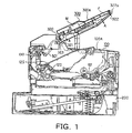
- Fig. 1 is a schematic cross-sectional view showing the entire structure of a sheet post-processing device and an image forming apparatus (printer) in accordance with a first embodiment.
- reference numeral 100 denotes a printer main body that functions as an image forming apparatus, which is connected to a computer, independently, or connected to a network such as LAN, forms (prints) an image on a sheet through a given image forming process on the basis of image information or a print signal which are transmitted from the computer or the network and discharges the printed sheet.
- a printer main body that functions as an image forming apparatus, which is connected to a computer, independently, or connected to a network such as LAN, forms (prints) an image on a sheet through a given image forming process on the basis of image information or a print signal which are transmitted from the computer or the network and discharges the printed sheet.
- a sheet post-processing device 300 takes up the sheets discharged from the printer main body 100 to the external by a flapper 301 that functions as a sheet discharge path change-over means, stacks the sheets or.
- a race down discharge portion 125 that functions as a sheet stacking means through a transporting portion within the sheet post-processing device in a face down state where an image surface of the sheet is directed downward, aligns the sheets due to a sheet aligning means, bundles the sheets for each of given jobs, staples the sheets at one position or a plurality of positions, and discharges and stacks the sheets, or merely discharges and stacks the sheets in the face down state.
- the sheet post-processing device 300 and the printer main body 100 are electrically connected to each other through a cable connector not shown, and used as a communication means that transfers various information.
- the sheet post-processing device 300 includes a casing portion 300A that stores the respective portions therein, and is detachably attachable with respect to the apparatus main body 100A of the printer main body 100 which will be described later.
- a plurality of sheets S are stacked within a sheet feeding cassette 200, and the uppermost sheet among the plurality of sheets is sequentially separated and fed by various rollers one by one. Then, a toner image is transferred onto an upper surface of the sheet S fed, in response to a given print signal supplied from the computer or the network, from the sheet feeding cassette 200 by an image forming portion 101 that forms a toner image through an image forming process of a so-called laser beam system within the printer main body 100, and then a hear and a pressure are applied to the sheet on which the toner image has been transferred by a fixer 120 at a downstream side thereof, to thereby permanently fix the toner image.
- the sheet S onto which the image has been fixed is turned back in a substantially U-shaped sheet transporting path that reaches a discharge roller 130 to reverse the image surface as shown in Fig. 1, and is then face-down-discharged from the printer main body 100 to the external by the discharge roller 130 in a state where the image surface is directed downward.
- the position of the flapper 301 of the sheet post-processing device 300 is determined on the basis of a control signal from a control portion not shown, to thereby select whether the sheet S is discharged as it is to a face-down (FD) discharge portion 125 disposed on an upper portion of the printer main body 100 (second sheet discharge path), or discharged through the sheet post-processing device 300 (first sheet discharge path).
- FD face-down
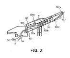
- Figs. 2 and 3 show cross-sectional views of the discharge roller 130 and the sheet post-processing device 300
- Fig. 4A is a cross-sectional view of the sheet post-processing device 300 taken along a line A-A of Fig 1
- Fig. 48 is a cross-sectional view taken along a line 3-B of Fig. 4A.
- Figs. 2 and 3 are diagrams for explaining the operation of the sheet post-processing device in accordance with the first embodiment.
- reference numeral 320 denotes a transporting roller
- 321 is a discharge sensor
- M is a jogger motor that functions as a driving source
- 322 is a sheet return member
- 323 is a reference wall against which a sheet trailing edge is abutted.
- the transporting roller 320 is disposed at the upper side of the downstream of the above-mentioned flapper 301 in the sheet transporting direction, and rotationally driven by a driving motor not shown.
- the discharge sensor 321 is disposed in the vicinity of the downstream side of the transporting roller 320 in the sheet transporting direction, and detects the leading edge and the trailing edge of the sheet transported by the transporting roller 320.
- the jogger motor M is a motor for driving a slide guide R310 and a slide guide L311 which will be described later, and a stepping motor is employed in this embodiment.
- the sheet return member 322 is disposed at the most downstream side in the sheet post-processing device 300 and is rotatable about a support shaft portion 322a as an axis.
- Fig. 2 shows an initial position of the sheet return member 322
- Fig. 3 shows a state in which the sheet return member 322 is pushed up by the sheet S.
- Figs. 4A and 4B are cross-sectional views for explanation of the operation of the slide guides that function as a first sheet discharge path open/close means and a sheet aligning means of the sheet post-processing device in accordance with the first embodiment.
- the slide guide R310 and the slide guide L311 which will be described in more detail later as guide members for aligning the sheets in the width direction.
- the flapper 301 rotates through a link not shown due to a solenoid not shown counterclockwise in Fig. 2. Then, when the end portion of the flapper 301 is positioned at a side lower than the nipping portion of the discharge roller 130 as shown in Fig. 2, the sheet S discharged from the discharge roller 130 to the external is drawn upward along the flapper 301, conveyed into the sheet post-processing device 300 and then conveyed to the first sheet stacking portion 300B for temporarily stacking the sheet S as shown in Fig. 2.
- the slide guide R310 and the slide guide L311 which are right and left with respect to the sheet conveying-in direction, respectively, retreat to positions external by a given amount in the width direction of the sheet S so that those slide guides R310 and L311 do not interfere with the conveyed sheet S, and wait for the entrance of the sheet S.
- the sheet post-processing device 300 when a first sheet S is discharged from the discharge roller 130 of the printer main body 100, the sheet S is conveyed into the device main body 300A so as to be drawn up by the flapper 301, and then transported onto the guide surface of the first sheet stacking portion 300B made up of the slide guide R310 and the slide guide L311 by the transporting roller 320 that is rotationally driven by the driving motor not shown.
- the first sheet stacking portion 300B functions as a sheet supporting means which temporally supports the sheets conveyed in the post-processing device.
- the guide surface of the first sheet stacking portion 300B is inclined at a given angle with respect to the horizontal direction and has inclined angles different between the upstream side and the downstream side in the sheet conveying-in direction as shown in Fig. 2.
- a bent portion 300C bent at an inclined angle ⁇ is formed between a given upstream section and a given downstream section.
- the guide surface of the first sheet stacking portion 300B has the bent portion 300C, to thereby prevent the bending of the center portion of the sheet S which is not guided by the slide guide R310 and the slide guide L311.
- a flag 321a of the discharge sensor 321 is rotated counterclockwise in Fig. 2, and then when the trailing edge of the sheet S passes through the transporting roller 320, as shown in Fig. 3, the flag 321a rotates due to its weight clockwise in Fig. 2, as a result of which the sheet trailing edge is pushed downward under pressure, and the sheet S surely drops down to the guide surface made up of the slide guide R310 and the slide guide L311. In this time, the discharge sensor 321 turns off.
- Figs. 4A and 4B are diagrams for explaining the structure of the slide guides taken along a line A-A of Fig. 1.
- Figs. 5A, 5B, 6A and 6B are diagrams for explaining the operation of the slide guides.
- the respective slide guide R310 and slide guide L311 can reciprocate in the right and left directions of Figs. 4A and 4B, that is, in a direction perpendicular to the sheet transporting direction (sheet width direction) while being guided by guide pins 314 (314a to 314d) disposed on a frame F, and travel due to the transmission of a driving force from the jogger motor M.
- each of the slide guide R310 and the slide guide L310 is substantially U-shaped in cross section so as to have the respective wall portions that guide both sides of the sheet S and a support portion that supports the upper and lower surfaces of the sheet S, as shown in Fig. 4B, and is structured to support the respective sheets discharged onto the first sheet stacking portion 300B by the lower surface of the U-shape and not to support the center portion of the sheet S in the width direction.
- the slide guide R310 is equipped with a rack portion 310a having a plate gear that is meshed with a stepped gear 317.
- the slide guide L311 is equipped with a slide rack L312 having a plate gear that is meshed with the step gear 317.
- the slide rack L312 is relatively movable with respect to the slide guide L311 through a coil spring 313.
- One end of the spring 313 is abutted against the slide guide L311, and the other end of the spring 313 is abutted against the slide rack L312 so as to urge toward a direction that widens the distance between the slide guide L311 and the slide rack L312.
- the slide rack L312 has an emboss portion 312a that moves within a rectangular hole portion 311a of the slide guide L311 side.
- Two reference pins R330 made of metal excellent in abrasion proof are disposed on side walls of the slide guide R310, and two reference pins L331 are disposed on side walls of the slide guide L311, and when the sheets are aligned, the slide guide R310 moves and the reference pin R330 and the reference pin L331 are abutted against both side edges of the sheets.
- the slide guide R310 and the slide guide L311 support are regulated in the height direction by the step gear 317 and a height regulating member 315.
- reference H denotes a stapler that functions as a processing means of stapling the sheets. Since the stapler H staples the left upper corner portions of an image surfaces of the sheets on which an image has been formed to bind the respective sheets, the stapler is fixedly disposed to the slide guide L311 side.
- the transporting roller 320 driven by the driving motor starts to rotate, and then the jogger motor M rotates to rotate the stepped gear 317, whereby the rack portion 310a of the slide guide R310 is driven and retreated outward.
- the slide guide L311 is retreated outward by being pushed by the emboss portion 312a after the slide rack 312 first relatively moves, and the emboss portion 312a of the slide rack 312 is abutted against the end surface of the rectangular hole portion 311a of the slide guide L311 at the left side of Figs. 4A and 4B when the jogger motor M rotates so that the step gear 317 rotates.
- the slide guide R310 is equipped with a flag portion 310f, and when the flag portion 310f moves to a given retreating distance, as shown in Fig. 6A, the flag portion 310f shields the photo sensor 316 from light, and at that time, the jogger motor M stops.
- the position is set as a home position.
- the jogger motor M rotates, and the slide guide R310 and the slide guide L311 move inwardly, and as shown in Figs. 4A and 4B, they stop at positions that are wider than the width of the entering sheet S by a given amount d.
- the slide guide L311 cannot be moved inward no longer since the guide pin 314c is abutted against the end portion.
- that position shown in Figs. 4A and 4B is a waiting position at which the side surface of the slide guide L311 becomes a reference position at the time of aligning the sheets in order.
- the waiting positions of the slide guide R310 and the slide guide L311 are set so that clearances at both sides thereof become given amounts d, respectively.
- the sheet S is taken up by the flapper 301 and guided into the sheet post-processing device 300, and then transported to the respective slide guide R310 and slide guide L311 by the transporting roller 320.
- the sheet S is transported along the guide surfaces of the slide guide R310 and the slide guide L311 after the leading edge of the sheet S has been detected by the discharge sensor 321, and a corner portion at the left side of the leading edge of the sheet (the left lower corner portion of Fig. 4A) is inserted into the opening portion of stapler H. Also, the center portion of the leading edge of the sheet S is abutted against the sheet return member 322, and if the sheet S is forcible, after the sheet S pushes up the sheet return member 322 counterclockwise in Fig. 2 (a direction indicated by an arrow) , the sheet return member 322 rotates clockwise due to its weight of the sheet S, to thereby align the trailing edge of the sheet S at the reference wall 323.
- the jogger motor M starts to rotate, and the slide guides that are at the waiting positions starts the following sheet aligning operation. That is, when the sheet aligning operation starts, the jogger motor M rotates in a direction along which the slide guides move inward. In this situation, the slide guide L311 cannot move because it is abutted against the guide pin 314c, and only the slide rack 312 disposed on the slide guide L311 moves in a direction along which the spring 313 is compressed. Therefore, during the sheet aligning operation, since only the slide guide R310 moves, the reference pin R330 of the slide guide R310 is abutted against the right side edge of the sheet S, and the sheet S is moved toward the left side of Figs.
- the slide guide R310 may be moved to a position where the distance between the slide guides R310 and L311 are narrower by a given amount than the width of the sheet S.
- the jogger motor M After the jogger motor M temporarily stops in a state of Figs. 5A and 5B where both end portions of the sheet S are abutted against the slide guide R310 and the slide guide L311, the jogger motor M starts reverse rotation, and then stops when the slide guide R310 again moves to the waiting position of Figs. 4A and 4B.
- the control for the amount of movement of the slide guide R310 during the above operation is managed by the number of drive pulses of the jogger motor M which is a stepping motor on the basis of the home position where the photosensor 316 is shielded from light.
- the slide guide R310 moves, the reference pin R330 is abutted against the side edge of the sheet (S2), and the left side edge of the sheet (S2) is moved until it is abutted against the reference pin L331 disposed on the slide guide L311, to thereby align the left side end portions of two sheets. Thereafter, the slide guide R310 moves up to the above-mentioned waiting position and stops.
- the slide guide L311 stops at the reference position so as not to move, and only the slide guide R310 moves whereby the left side end portions of the respective sheets are aligned at the reference position, as a result of which the binding operation made by the stapler H that is fixedly disposed at the slide guide L311 side is accurately and surely conducted.
- the widths of the respective transported sheets are varied in one job or in the case where the sheet size changes, for example, from LTR to A4 in one job, since the positions of the left end portions of the respective sheets are constantly aligned, excellent advantages that the finishing of the binding operation by the stapler H becomes accurate and fine are obtained.
- the jogger motor M is rotationally driven so that the slide guide R310 moves in a direction where it is widened from the state shown in Figs. 5A and 5B.
- the slide guide R310 starts to move, concerning the slide guide L311, the slide rack 312 moves toward the left side of Figs. 5A and 5B, and the slide guide L311 side per se does not moves immediately.
- the bundle of sheets drop down to the face-down (FD) discharge portion (FD tray) 125 of the printer main body 100 that functions as a second sheet stacking portion and are then stacked one on another.
- the FD discharge portion 125 of the printer main body 100 is commonly employed as a member of stacking the bundle of sheets discharged from the sheet post-processing device 300 without providing an exclusive stacking portion, there can be provided the downsized and inexpensive sheet post-processing device.
- the sheet post-processing device 300 is mounted on the upper portion of the device main body 100A of the printer main body 100 that functions as the image forming apparatus, and the transporting paths of the sheets discharged from the device main body 100A are changed over by the flapper 301, there can be provided an inexpensive sheet post-processing device that does not require a switch back mechanism in order to discharge and stack the sheets on which an image has been formed in order of pages, has no disadvantage that the interval of sheets must be made wide for conducting the switch back, and also does not increase an area where the device is located.
- the operation of the flapper 301 and relevant portions is controlled in such a manner that at least one succeeding sheet is stacked on the FD discharge portion 125 of the printer main body 100 through the sheet post-processing device 300 without discharging the sheet directly to the FD discharge portion 125.
- the operation enables the binding portion of the bundle of sheets previously discharged to be covered with a sheet S that drops down subsequently, thereby being capable of preventing the catching of the sheet S thereafter discharged directly to the FD discharge portion 125 from the printer main body 100.
- the slide guide L311 may also operate. This can be realized, for example, by making the slide guide L311 identical with the slide guide R310 in the structure.
- both of the slide guide R310 and the slide guide L311 are structured to operate.
- only any one of those slide guides R310 and L311 may operate.
- Fig. 7 is a block diagram showing the structure of electric components in the sheet post-processing device in accordance with this embodiment.
- the structure of the electric components of the sheet post-processing device 300 is made up of a control board not shown, the stapler H, the driving motor M1, the jogger motor M, the solenoid SL that operates the flapper, the discharge sensor 321, the home position sensor 316 of the slide guide R310 and the slide L321 (hereinafter referred to as "jogger HP sensor 316"), and a stacking amount sensor 715 that detects the amount of stacks on the FD discharge portion of the printer main body 100.
- a one-chip microcomputer including a ROM and a RAM therein which functions a storing means
- CPU 702 central processing unit
- motor driver 703 that drives the stapler H upon receiving a control signal from the CPU 702
- driving motor driver 707 that rotates the driving motor M1 upon the control signal from the CPU 702
- jogger motor driver 709 that rotates the jogger motor M upon receiving the control signal from the CPU 702
- solenoid driver 711 that drives the flapper solenoid SL upon receiving the control signal from the CPU 702 Likewise.
- sensor signals from the discharge sensor 321, the jogger HP sensor 316 and the stacking amount sensor 715 are input into the CPU 702 to control the sheet post-processing device 300.
- the CPU 702 conducts serial communication with an image controller 701 that is mounted on the printer main body 100 and transmits/receives information for controlling the printer main body 100 and the sheet post-processing device 300 to control those devices together with the image processing.
- Figs. 8 to 15 are flowcharts showing the control of the CPU 702 that functions as an error handling means, a sheet discharge path change-over control means and an error handling operation necessity judging means in the first embodiment.
- the control of the CPU 702 will be described in order.
- Fig. 8 is a flowchart showing an initializing operation of the sheet post-processing device 300.
- the CPU 702 is initialized (S801).
- the setting of various specific registers such as a timer setting, an interruption setting, a serial communication setting and an I/O port setting is conducted.
- the CPU 702 cancels the communication interruption and waits for a command from the image controller 701.
- An initial command and a second command transmitted from the controller 701 are given codes.
- the number of optional devices connected to the printer main body 100 and the confirmation for connections are conducted by the initial command, the second command and a predetermined data (referred to as "status") code returned to the image controller 701 by the CPU 702 (S802 and S803).
- the sheet post-processing device is initialized (S804 to S808).
- the stapler H is initialized (S804).
- the stapler H has a staple cartridge sensor 704 not shown for predicting no staple and a stapler home position sensor 705 indicating that the clincher of the stapler is at an initial position.
- the initialization of the stapler H is completed by returning the clincher to the initial position. If the clincher is not at the initial position, the motor is rotated for a given period of time in a direction opposite to the rotating direction for normally stapling to return the clincher to the initial position.
- the CPU 702 completes the initialization at the time where the jogger HP sensor detects the slide guide R310 and the slide guide L311 while rotating the jogger motor M in a direction where the slide guides R310 and L311 are opened by a given number of steps (S806).
- a jogger motor failure operation not shown is conducted (S807).
- the jogger motor failure is judged on the basis of the given number of steps, but the same effect is obtained on the basis of the rotation for a given period of time.
- the discharge sensor 321 detects the residual sheet within the sheet post-processing device 300, and if there exists a sheet, a jam clearance operation shown in Fig. 13 is conducted (S808).
- the residual sheet within the device is detected by only the sheet detection of the discharge sensor 321, but if the driving motor M1 is driven for a given period of time, and the presence/absence of the sheets is monitored by the discharge sensor during the period of time, a range where the residual sheets within the device can be detected can be widened. with the above operation, the initialization of the sheet post-processing device 300 is completed.
- Fig. 9 is a flowchart showing an operation in which the sheet post-processing device 300 is on standby.
- the sheet post-processing device 300 When the sheet post-processing device 300 is on standby, there are mainly an operation for holding page information not shown which is transmitted from the image controller 701 and an operation for waiting for a sheet conveying-in prediction.
- the page information has the sheet size and operations for the page, and when the page information is decided, a latch command is sent to the CPU 702 from the image controller 701.
- the respective commands indicating "a size of A4" + "a job header” + “latch” in a first-page information are sent from the image controller 701 to the CPU 702
- the respective commands indicating "a size of A4" + “latch” in a second-page information is sent from the image controller 701 to the CPU 702
- the respective commands indicating "a size of A4" + "job completion” + “latch” in a third page information is sent from the image controller 701 to the CPU 702.
- a command that inquires an operating period of time between pages, and when the image controller 701 designates information of adjacent pages to the CPU 702 by commands, the CPU 702 informs the image controller 701 of a required period of time between the pages on the basis of the information.
- the operating period of time is 500 ms in case of the first page (the first page is designated in this case), 500 ms between the first page and the second page, and 500 ms between the second page and the third page. If a succeeding job is designated, the operating period of time is 6 seconds between the third page and a first page of the succeeding job.
- the period of time of 6 seconds is a period of time during which the sheet post-processing device 100 staples a bundle of sheets on the slide guides, drops down to the face-down discharge portion 125 of the printer main body, and then detects the amount of stacks which will be described later.
- the standby operation first stops the driving motor M1 (S901), stops the flapper solenoid SL (S902) and then analyzes the command that can be processed during standby.
- the convey-in prediction command is received, it is first judged whether the page information corresponding to the convey-in prediction command is "page header", or not (S907). If it is the page header, the page counter of the job is initialized to 1 (S908), the driving motor M1 is driven (S909), the flapper solenoid SL is driven (S910) and the operation is shifted to the sheet transporting operation. In addition, the slide guides are moved to the sheet waiting position (S911).
- the jogger HP sensor is monitored, and when the slide guides are not moved from the initial positions although the jogger motor M is driven by the given number of steps, the jogger motor failure operation is conducted.
- Fig. 10 is a flowchart showing the sheet transporting operation of the sheet post-processing device 300.
- a sheet leading edge is detected by the discharge sensor 312, and if the sheet leading edge cannot be yet detected, it is judged by the timer whether a sheet delay jamming occurs, or not, and if a time is over, the jam clearance operation shown in Fig. 13 is conducted (S1002, S1003).
- the discharge sensor is again monitored, and it is confirmed that the sheets exist within a given period of time (S1004, S1005). If no sheet is detected during the given period of time, it is judged that some transportation abnormality occurs, and the jam clearance operation shown in Fig. 13 is conducted.
- Fig. 11 is a flowchart showing the stapling operation.
- the driving motor M1 is stopped (S1101), and the flapper solenoid SL is stopped (S1102).
- the bundle of sheets due to the slide guides for the stapling operation is aligned (S1103).
- the page counter is 1, or not (S1113). If the page counter is 1, the operation of S1106 is conducted without stapling. If the page counter is not 1, the stapler motor is driven (S1104) to start the operation of the stapling operation.
- the staple cartridge sensor 704 is monitored, and it is judged whether the staple motor correctly operates by moving the clincher of the stapler from the initial position, or not (S1105), and if the staple cartridge sensor 704 continues to detect the clincher at the initial position for a given period of time, a stapler motor failure operation not shown is conducted. Also, when the stapling operation is correctly conducted, since the staple cartridge sensor 704 again detects that the clincher is returned to the initial position after the given period of time, if the clincher at the initial position cannot be detected for the given period of time, the stapler motor failure operation not shown is conducted.
- the flapper solenoid SL is then driven (S1106), and the slide guides are moved to the initial position (S1107). In this situation, similarly to the initialization, it is judged whether the slide guides are returned to the initial position, or not (S1108), and if not, the jogger motor failure operation not shown is conducted.
- the slide guides are moved to the initial position, the bundle of sheets stapled on the slide guides drop down on the face-down discharge portion 125 of the printer main body 100.
- a drop period waiting operation is conducted (S1109). After the bundle of sheets has dropped down, the flapper solenoid stops (S1110), the discharge completion is notified the image controller 701 of (S1111), and the stapling operation is completed. Then, the slide guides move to the waiting position (S1112).
- the discharge completion is notified the image controller of, but the discharge completion of a sheet of L-th page is notified the image controller of at the point in time when the stapling operation has been completed. If a job is for one page or (N+1) pages or more, the stapling operation is not conducted.
- Fig. 12 is a flowchart showing the control operation of the jogger motor M.
- a operation mode and a moving position are designated the above-mentioned initializing operation, the sheet transporting operation and the stapling operation, so that the jogger motor operates correspondingly and that the slide guides move to a desired position. If the control is normally completed, a normal operation flag is set when the operation is completed, and the operation completion is notified the respective operations that request the operation of.
- the moving position is represented by an absolute position with setting the initial position of the slide guides to 0, and a moving direction is found out from the current position and a position to be moved.
- Step S1203 it is judged which operation mode should be conducted. If the movement of the slide guides to the initial position is designated in Step S1201, a moving speed P1 is set (S1202), but if the movement of the slide guides to the waiting position for aligning the sheets is designated in Step S1203, a moving speed P2 is set (S1204), and if not so, a moving speed P3 is set as a movement at the time of aligning the sheets (S1205).
- the moving speeds P1, P2 and P3 have the following relationship.
- the speed P1 is an important speed for regularly dropping down the bundle of sheets to the face-down discharge portion 125 of the printer main body 100 from the slide guides 310 and 311, and a speed of 50 mm/sec or higher.
- the number of movement pulses is calculated on the basis of the current position and a designated position (S1206), and a moving direction is determined on the basis of the calculated information (S1207).
- the jogger motor starts to be driven (S1208), and it is judged whether a given number of pulses are driven, or not (S1209).
- the addition and subtraction of the number of pulses and a change-over of an exiting phase are conducted by a timer interrupting operation not shown.
- Fig. 13 is a flowchart showing the jam clearance operation of the sheet post-processing device.
- the delay jamming flag is set (S1301), and the sheet delay jamming is notified the image controller 701 of.
- the residual jamming flag is set (S1310), and the sheet residual jamming is notified the image controller 701 of.
- the residual sheet jamming flag is set (S1311) and the sheet residual jamming is notified the image controller 701 of.
- the jamming flag is reset (S1305), and this is informed the image controller 701 of, and the operation is shifted to the operation of initializing the sheet post-processing device.
- This operation assumes that the operator removes the jammed sheets while the cover opens or closes. However, even if the jammed sheets are not removed, the in-device residual sheets are detected through the initializing operation, and this can be informed the image controller of. Also, even if jamming occurs during the stapling operation or the slide guides movement, those driven systems can be moved co the initial position through the initializing operation.
- Fig. 14 is a flowchart showing a operation when a staple of the stapler is jammed.
- the staple jamming flag is set (S1401), and this is notified the image controller 701 of, and all of the driving systems stop at the same time (S1402).
- the operator opens the slide guides so as to readily conduct the staple jam clearance operation (S1403). Even in this situation, similarly to the initializing operation, it is monitored whether the slide guides are returned to the initial position, or not, and if not returned, the jogger motor failure operation not shown is conducted (S1404). After the slide guides are returned to the initial position, it is confirmed that the staple cartridge is removed by the operator (S1405), and that the staple cartridge is set (S1406) and the staple jamming flag is reset (S1407), and this is notified the image controller 701 of. This assumes the operation of removing the abnormal staple within the staple cartridge by the operator.
- Fig. 15 is a flowchart showing the emergent stop and the automatic sheet discharging operation of the sheet post-processing device 300.
- the image controller 701 transmits an emergent stop command to the CPU 702.
- Step S1501 it is judged whether the sheet post-processing device 300 is transporting the sheets, or not (S1501), and if the sheet post-processing device 300 is transporting the sheets, it is judged whether the slide guides are controlled, or not (S1502). If the slide guides are controlled, the CPU waits for the completion of this operation in Step S1503. In this case, since there is the possibility that the sheets remain on the slide guides or the transporting path, a flag that indicates that there exist the discharge enable residual sheets is set, and this is notified the image controller 701 of.
- Step 1507 and the subsequent steps are repeated. If the automatic sheet discharge command is received, the timer for the automatic sheet discharging operation starts (S1510), the driving motor M1 is driven (S1511) and the sheets that are being transported are transported up to the slide guides. In this operation, the flapper solenoid SL is not allowed to operate.
- the sheets that remain within the sheet post-processing device in the operation of the emergent stop operation are clearly sheets that are being subjected to the stapling operation, which is a part of job.
- the sheets that remain in the printer main body 100 are recovered by the image controller 701 later, they are unnecessary for the job. Therefore, by not operating the flapper solenoid SL the unnecessary sheets can be discharged onto the face-down discharge portion 125 of the printer main body 100.
- Step S1512 After the driving motor M1 has been driven for a given period of time (S1512), the driving motor Ml stops (S1513). Then, it is confirmed by the discharge sensor 321 whether the sheets are discharged, or not (S1514), and if the sheets are detected, the jam clearance operation of Fig. 13 is conducted as a discharge disenable in-device residual sheet jamming. If the automatic sheet discharge is completed, the operation is returned to the standby operation. If the sheets are not being transported in Step S1501, it is judged whether the stapling operation is being conducted, or not (S1520). If the stapling operation is being conducted, the job is going to be completed, and the CPU waits for the completion of the stapling operation without interrupting the operation (S1521).
- the automatic sheet discharge enable flag is set (S1523), to thereby complete the emergent stop operation.
- the automatic sheet discharge enable flag is set (S1523), to thereby complete the emergent stop operation.
- the stapling operation is not being conducted in Step 51520, it is judged whether it is on standby, or not (S1522). If it is on standby, the operation of S1523 is conducted. Similarly, in this case, even if the automatic sheet discharge command is received, it is unnecessary to conduct the automatic sheet discharging operation. If it is not on standby in Step S1522, since it is in the initial state or in the abnormal state, the automatic sheet discharge enable flag is not set.
- the sheet post-processing device having at least the stapler is disposed above the discharge portion on the upper surface of the apparatus main body. Then, since the sheet post-processing device is so structured as to drop down the sheets that have been subjected to post-processing by the sheet post-processing device on the discharge portion of the apparatus main body side which is located below so as to stack the sheets, the simplification and a reduction of the costs of the sheet post-processing device can be realized.
- the stapling means is described as the sheet post-processing means, but the same effects are obtained if the sheet post-processing with the sheet aligning operation is conducted, for example, even if a punching means that opens a punch hole in a bundle of sheets, a book binding means having a sheet folding means after the sheets have been stapled, a book binding means that adhering the edges of sheets, or other easy binding means is employed.
- a measuring means that counts the number of sheets stacked on a first sheet stacking portion. If a comparing means that compares the number of sheets M that has been counted by the measuring means with a stapling permissible number of sheets (post-processing permissible number of sheets) N detects that a relationship of M > N is satisfied, the slide guides are opened without conducting the sheet post-processing, and a bundle of sheets are allowed to drop down on the face-down discharge portion 125 of the printer main body 100.
- the measuring means may adopt a method of mechanically counting the number of sheets as well as a method of calculating the number of sheets by, for example, mechanically and optically detecting the thickness of the bundle of sheets, or detecting the weight of the bundle of sheets.
- the sheets that have already been stacked on the first sheet stacking portion can be simply stacked on the face-down discharge portion 125 in a short period of time, and the processing can be implemented under simple control without increasing the costs in the case where a job for sheets the number of which exceeds the post-processing permissible number is designated.
- control can be as follows: the bundle of sheets that have been already stacked on the first sheet stacking portion are allowed to drop down on the face-down discharge portion 125 of the printer main body 100 by opening the slide guides as described above, and thereafter the sheets that have been conveyed in the first sheet stacking portion can be allowed to drop down on the face-down discharge portion 125 that functions as a second sheet stacking portion for each of the sheets without being stacked on the first sheet stacking portion and also being subjected to post-processing.
- the sheets that have already been stacked on the first sheet stacking portion can be simply stacked on the face-down discharge portion 125 in a short period of time, and the processing can be implemented under simple control without increasing the costs in the case where a job for sheets the number of which exceeds the post-processing permissible number is designated.
- the slide guides 310 and 311 are opened, and the bundle of sheets are allowed to drop down on the face-down discharge portion 125 that functions as the second sheet stacking portion of the printer main body 100.
- the subsequent sheets are not set and they are stacked on the face-down discharge portion 125 of the printer main body 100 sheet by sheet in the same way. Since those sheets are not stapled, it is more preferable that the error handling operation can be conducted without transporting the sheets to the sheet post-processing device 30.
- the above comparing means judges that the relationship of M > N is satisfied, if the sheet bundle binding command from the image forming apparatus is accompanied with an (M+1)th sheet or the subsequent sheet, not only the bundle of sheets that have been already stacked on the first sheet stacking portion but also the (M+1)th sheet and the subsequent sheets are conveyed in the first sheet stacking portion of the sheet post-processing device from the image forming apparatus.
- control may be conducted as follows. That is, the bundle of sheets that have been already stacked on the first sheet stacking portion are allowed to drop down on the face-down discharge portion 125 of the printer main body 100 by opening the slide guides as described above, and thereafter the flapper solenoid SL that functions as the sheet discharge path change-over means is turned off, to thereby stack the subsequent sheets directly on the face-down discharge portion 125 of the printer main body 100 sheet by sheet without being stacked on the first sheet stacking portion of the sheet post-processing device 300.
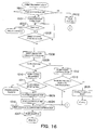
- Fig. 16 shows a sheet transporting operation in accordance with the second embodiment.
- the contents of the operation are substantially identical with the operation shown in the chart of Fig. 10, but there are added an operation of turning off the flapper solenoid SL in Step S1603 while the operation of Steps S1011 and S1016 is conducted, and a step of setting a flag that indicates that the staple over operation of Step S1604 is conducted.
- This flag is judged in an initial step S1601 of the sheet transporting operation, and if the flag is not set, the normal stacking operation is conducted. However, if the flag is set, after waiting time in step S1602, the control is skipped to the operation of Step S1016.
- the waiting time is identical with a period of time required until the sheets are stacked on the slide guides.
- a set flag indicating that the staple over operation is conducted is reset after the page information of the subsequent job indicates the header page (an operation of S907 in Fig. 9) although not shown.
- the above control is conducted, thereby making it possible to regularly discharge the sheets that have not been stapled to the face-down discharge portion 125 of the printer main body 100.
- the comparing means judges that the relationship of M + X > N is satisfied, when the sheets that receives the sheet bundle binding command from the image forming apparatus is (M+X+1)th sheet or the subsequent sheet, after the sheets that have been already transported in the post-processing device in addition to the bundle of sheets that have been already stacked on the first sheet stacking portion are stacked on the first sheet stacking portion, the slide guides are opened as described above, and the bundle of sheets are allowed to drop down on the face-down discharge portion 125 of the printer main body 100. Thereafter, the flapper solenoid SL that functions as the sheet transporting path changing means is turned off to stack the subsequent sheets not on the sheet post-processing device 300, but directly on the face-down discharge portion 125 of the printer main body 100 sheet by sheet.
- the slide guides 310 and 311 are opened, and the bundle of sheets are allowed to drop down on the face-down discharge portion 125 of the printer main body 100. Then, the subsequent sheets are stacked on the face-down (FD) discharge portion of the printer main body 100 sheet by sheet in the same manner without aligning the sheets.
- a measuring means that counts the number of sheets stacked on the first sheet stacking portion, and even after a comparing means that compares the number of sheets M counted by the measuring means with a stapling permissible number of sheets (post-processing permissible number of sheets) N detects that the relationship of M > N is satisfied, when the sheet bundle binding command from the image forming apparatus is accompanied with an (M+1)th or subsequent sheet, the slide guides are opened and the bundle of sheets that have been already stacked on the fist sheet stacking portion are allowed to drop down on the face-down discharge portion 125 of the printer main body 100.
- the sheets transported to the first sheet stacking portion are stacked on the slide guides as in the normal operation once, and at the point in time when a given number of sheets are stacked on the first sheet stacking portion, the bundle of sheets are allowed to drop down on the face-down discharge portion 125 of the printer main body 100 without being stapled likewise, and subsequently the operation is repeated until the job is completed. Since the bundle of sheets are allowed to drop down at the point in time when a given number of sheets are thus stacked, the stacking property of the sheets on the face-down discharge portion 125 becomes satisfactory.
- the processing is implemented under simple control without increasing the costs in the case where a job for sheets number of which exceeds the post-processing permissible number is designated.
- the given number of sheets is a value stored in the CPU 702 in advance although it may be arbitrary. Also, an interval between a final page of the given number of sheets and a first page of the succeeding given number of sheets is notified the image controller 701 of so as to provide a given period of time. Since the image controller 701 inquires of the CPU 702 a period of time between the respective pages at a timing where the page information transmitted for each of pages is transmitted to the CPU 702 from the image controller 701, the above notification replies to the image controller 701 at that timing.
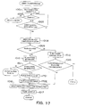
- Fig. 17 shows the sheet transporting operation in accordance with the third embodiment.
- the contents of the operation are substantially identical with the operation shown in the flowchart of Fig. 10, except the following operation. That is, after the slide guides are opened in Step S1010, and its confirmation is conducted, a flag indicating that the staple over operation is conducted is set in Step S1701, and the page counter is cleared once in Step S1702. Then, since it is judged that the page counter value of a succeeding page is less than N in Step S1009, the aligning operation of Step S1012 is conducted. In this situation, if that page is a job completion page, it is judged that the job is completed in Step S1013, and the operation is shifted to the stapling operation.
- a given number of sheets is set to a permissible stapling number of sheets N, but if an arbitrary integer Y of (N - 1) or less is set without clearing the page counter to 0 when the page counter is cleared once, a bundle of sheets of the (N - Y) number can be allowed to drop down on the face-down discharge portion 125 of the printer main body 100.
- a flag indicating that the staple over operation is conducted is set, only the sheet aligning operation and the dropping operation are conducted, but the stapling operation is not conducted.
- a flag indicating that the set staple over operation is conducted is reset after the page information of a succeeding job is indicative of a header page (the operation of Step S907 in Fig. 9) although not shown.
- the error handling operation can be conducted at a low cost and under the simple control without any special provision of a new mechanism.
- a sheet post-processing device and an image forming apparatus (printer) in accordance with a fourth embodiment have the same structure as that in the first embodiment shown in Figs. 1 to 7. Description of the identical structure with that in the first embodiment will be omitted.
- Fig. 18 shows an operation in a state where the sheet post-processing device 300 is on standby.
- the non-sheet-transporting operation shown in Fig. 19 is conducted immediately.
- a non-transportation flag is set so that a non-sheet-transporting operation is conducted till a final page of the job now (S914), and a non-sheet-transporting operation shown in Fig. 19 is conducted.
- a page counter of the job is initialized to 1 (S908), the driving motor Ml is driven (S909), the flapper solenoid SL is further driven (S910) and the operation is shifted to the sheet transporting operation.
- the slide guides are moved to a sheet waiting position (S911). Then, in the case where the slide guides are not moved from the initial position although the jogger HP sensor is monitored and the jogger motor M is driven by a given number of steps, a jogger motor failure operation is conducted.
- Fig. 19 is a flowchart showing the non-sheet-transporting operation.
- This operation is executed in the case where the sheet size that cannot be dealt with by the sheet post-processing device is conveyed in from the printer main body 100.
- the timer starts (S601) to wait for the elapse of that period of time (S602).
- the sheet post-processing device in the image forming apparatus that discharges the sheets on which an image has been formed onto the upper surface of the apparatus, since the sheet post-processing device is disposed above the discharge portion of the upper surface of the apparatus main body, and the sheets that have been subjected to post-processing by the sheet post-processing device are allowed to drop down on the discharge portion of the apparatus main body side that is positioned to be lower so as to be stacked on the discharge portion, the sheet post-processing device can be simplified and a low cost can be realized.
- the present invention is not limited to this structure, but the same effects can be obtained if the sheet post-processing with the sheet aligning operation is conducted, for example, even if a punching means that opens a punch hole in a bundle of sheets, a book binding means that adhering the edges of sheets, or other easy binding means is employed.
- the description is given of the example in which the sheets are discharged directly to the face-down discharge portion 125 of the printer main body without introducing the sheets to the sheet post-processing device in case of the sheet size that can not be dealt with by the sheet post-processing device.
- the judgment of whether the sheets can be dealt with by the sheet post-processing device, or not is not limited to the sheet size, but the judgment may be made on the basis of other conditions.
- the sheet post-processing device it is not judged on the basis of the sheet size whether the sheet post-processing device can deal with the sheets, or not, as in the above fourth embodiment, but the judgment is made on the basis of other conditions or such conditions including the sheet size, and in case of the sheets that cannot be dealt with by the sheet post-processing device, the sheets are discharged to the face-down discharge portion 125 of the printer main body 100.
- some of the image forming apparatuses provide a function of discriminating the kind of sheets or a function of designating the kind of sheets.
- the communicating means with the image controller 701
- the sheet post-processing device can deal with nothing other than a plain paper, in an operation of a flowchart shown in Fig. 18 (S913), it is judged whether the sheet is a plain paper, or not, instead of the judgment of the sheet size, and if the sheet is not the plain paper, the operation is advanced to Step S914. With this operation, sheets that cannot be dealt with by the sheet post-processing device can be readily discharged in accordance with the kind of sheets onto the face-down discharge portion of the printer main body 100.
- Step S913 it is judged whether the sheet is a plain paper, or not, and if the sheet is not the plain paper, the operation is advanced to Step S914.
- the sheet supporting means portion 300B it may be determined whether the sheet can be supported (stacked) by the sheet supporting means portion 300B, or not, or whether the post-processing can be conducted, or not.
- the number of sheets to be processed is determined as in a case of conducting the stapling operation, whether the processing is enabled, or not, is based on the total number of sheets, and if adhering is conducted as in the book binding operation, since there is a case where adhering cannot be conducted depending on the material of the sheets, judgment is made on the basis of the material.
- the sheets that can be physically identified are judged as the kind of sheets, such as the sheet weight per one sheet, an OHP sheet, a glossy paper, a colored paper or a perforated paper.
- the image controller judges whether sheets are discharged to the face-down discharge portion 125 of the printer main body or the sheet post-processing device in accordance with the intended usage in a printing request transmitted from a host computer or a designation.
- the image controller 701 completely ignores the above processing and gives all of page information to the sheet post-processing device.
- the sheet post-processing device automatically determines whether the sheets are discharged as they are to the face-down discharge portion 125 of the printer main body 100 or introduced into the self device to conduct the post-processing by conducting the operation described in the above-mentioned first embodiment, thereby making it possible to smoothly process the job.
- the processing can be appropriately conducted without conducting such a useless process that the sheets that will not be post-processed are introduced into the sheet post-processing device, and availability is improved.
- a conveyed sheet is temporarily stacked on a pair of slide guides (310, 311), and after post-processing such as stapling is conducted on the sheets, the slide guides (310, 311) are opened to drop down the sheets on a face-down discharge portion (125) on an upper surface of a printer (100). If the number of sheets temporarily stacked on the slide guides (310, 311) exceeds the post-processing possible number of sheets, the slide guides (310, 311) are opened to drop down the sheets on the face-down discharge portion (125).
- a flapper (301) is changed over so that the sheets transported from the printer main body (100) are discharged directly to the face-down discharge portion (125) and stacked thereon.
Landscapes
- Engineering & Computer Science (AREA)
- Mechanical Engineering (AREA)
- Pile Receivers (AREA)
- Folding Of Thin Sheet-Like Materials, Special Discharging Devices, And Others (AREA)
- Paper Feeding For Electrophotography (AREA)
- Separation, Sorting, Adjustment, Or Bending Of Sheets To Be Conveyed (AREA)
Abstract
Description
Claims (39)
- A sheet post-processing device, comprising:a first sheet discharge path through which a sheet transported from an image forming apparatus is transported to sheet stacking means disposed in said image forming apparatus;first sheet discharge path open/close means which is disposed in said first sheet discharge path, and closes said first sheet discharge path to temporarily support the sheet transported from said image forming apparatus, or opens said first sheet discharge path to transport the sheet transported from said image forming apparatus to said sheet stacking means;processing means which is disposed in said first sheet discharge path and conducts post-processing with respect to the sheet temporarily supported by said first sheet discharge path open/close means;sheet discharge path change-over control means that controls sheet discharge path change-over means that changes over a discharge path, to which the sheet discharged from said image forming apparatus is discharged, to said first sheet discharge path or a second sheet discharge path through which the sheet discharged from said image forming apparatus is discharged directly to said sheet stacking means;error handling operation necessity judging means that judges whether error handling operation that should be conducted with respect to a sheet unsuitable for the post-processing by said processing means is conducted or not; anderror handling means that controls at least one of said first sheet discharge path open/close means and said sheet discharge path change-over means to conduct said error handling operation.
- A sheet post-processing device according to claim 1, further comprising:measuring means that measures the number of sheets that are temporarily supported by said first sheet discharge path open/close means;storing means that stores the number of post-processing permissible sheets N which can be post-processed in said processing means; andcomparing means that compares the number of sheets M measured by said measuring means with the number of sheets N stored by said storing means, wherein:said error handling operation necessity judging means judges that the error handling operation is conducted if a result made by said comparing means satisfies a relationship of M > N; andsaid error handling means controls said first sheet discharge path open/close means so as to open said first sheet discharge path to transport the sheet temporarily supported by said first sheet discharge path open/close means to said sheet stacking means.
- A sheet post-processing device according to claim 2,
further comprising sheet aligning means that aligns the sheets temporarily supported by said first sheet discharge path open/close means;
wherein if said error handling operation necessity judging means judges that the error handling operation is conducted, said error handling means controls said first sheet discharge path open/close means so as to align only the sheets temporarily supported by said first sheet discharge path open/close means through said sheet aligning means and so as to open said first sheet discharge path to transport the sheets temporarily supported by said first sheet discharge path open/close means to said sheet stacking means. - A sheet post-processing device according to claim 2,
wherein if said error handling operation necessity judging means judges that the error handling operation is conducted, said error handling means controls said first sheet discharge path open/close means so as to open said first sheet discharge path and transport the (M+1)th and subsequent sheets to said sheet stacking means. - A sheet post-processing device according to claim 2,
wherein if said error handling operation necessity judging means judges that the error handling operation is conducted, said error handling means controls said sheet discharge path change-over means so as to transport the (M+1)th and subsequent sheets to said second sheet discharge path. - A sheet post-processing device according to claim 5,
wherein when a relationship of M + X > N is satisfied assuming that the number of sheets transported to said first sheet discharge path is X, said error handling means controls said sheet discharge path change-over means so as to transport the (M+X+1)th and subsequent sheets to said second sheet discharge path. - A sheet post-processing device according to claim 2,
further comprising sheet aligning means that aligns the sheets temporarily supported by said first sheet discharge path open/close means;
wherein if said error handling operation necessity judging means judges that the error handling is conducted, said error handling means controls said first sheet discharge pathopen/close means so as to temporarily support the (M+1)th and subsequent sheets every given number of sheets, align the sheets by said sheet aligning means, and transport the sheets to said sheet stacking means. - A sheet post-processing device according to claim 7,
further comprising communication means that conducts communication with said image forming apparatus,
wherein if said error handling operation necessity judging means judges that the error handling operation is conducted, said error handling means, in controlling said first sheet discharge path open/close means so as to temporarily support the (M+1)th and subsequent sheets every given number of sheets, notifies said image forming apparatus of a period of time between a last sheet of a given number of sheets and a succeeding sheet through said communication means, to widen an interval between the sheets transported from said image forming apparatus. - A sheet post-processing device according to claim 1,
wherein said processing means includes at least one of stapling means that binds sheets by stapling, punching means that punches the sheets, book binding means that binds the sheets by stapling and folds the sheets, and book binding means that adheres edges of the sheets with paste. - A sheet post-processing device according to claim 1,
further comprising communication means that conducts communication with said image forming apparatus,
wherein when said error handling operation necessity judging mean judges that the error handling operation is conducted on the basis of information on the sheets that are going to be post-processed in said processing means which is transmitted from said image forming apparatus by said communication means, said error handling means controls said sheet discharge path change-over means so as to transport the sheets transported from said image forming apparatus to said second sheet discharge path. - A sheet post-processing device according to claim 10,
wherein said error handling operation necessity judging means judges whether the sheets are suitable for post-processing by said processing means or not on the basis whether the sheets can be supported by said first sheet discharge path open/close means or not, and if the sheets cannot be supported by said first sheet discharge path open/close means, said error handling operation necessity judging means judges that the sheets are not post-processed. - A sheet post-processing device according to claim 11,
wherein whether the sheets can be supported by said first sheet discharge path open/close means or not is judged on the basis of a sheet size. - A sheet post-processing device according to claim 11,
wherein whether the sheets can be supported by said first sheet discharge path open/close means or not is judged on the basis of a sheet weight. - A sheet post-processing device according to claim 11,
wherein whether the sheets can be supported by said first sheet discharge path open/close means or not is judged on the basis of the number of sheets. - A sheet post-processing device according to claim 2,
wherein whether the sheets are suitable for post-processing by said processing means or not is based on whether the kind of sheets is suited to the post-processing by said processing means or not. - A sheet post-processing device according to claim 15,
wherein the kind of sheets can be physically identified, and includes at least one of a sheet different in the weight per one sheet, an OHP sheet, a glossy paper, a colored paper and a perforated paper. - A sheet post-processing device according to claim 1, further comprising communication means that conducts communication with said image forming apparatus;
wherein when said sheet post-processing device per se is in an abnormal state, error handling operation necessity judging means judges that the post-processing is not conducted regardless of the contents of information on a sheet which is transmitted from said image forming apparatus by said communication means. - A sheet post-processing device according to claim 1, further comprising communication means that conducts communication with said image forming apparatus;
wherein information on only the sheets that are going to be post-processed by said image forming apparatus is transmitted from said image forming apparatus through said communication means. - A sheet post-processing device according to claim 1, further comprising communication means that conducts communication with said image forming apparatus;
wherein information on all of the sheets that are subjected to an image forming process by said image forming apparatus is transmitted from said image forming apparatus through said communication means. - A sheet post-processing device according to claim 1,
wherein said first sheet discharge path open/close means is disposed above said sheet stacking means disposed on an upper surface of said image forming apparatus main body. - An error handling method with respect to a sheet that is not suitable for post-processing in an image forming apparatus having a sheet post-processing device that conducts the post-processing on the discharged sheet, wherein:said sheet post-processing device comprises:a first sheet discharge path through which the sheet transported from said image forming apparatus is transported to a sheet stacking means disposed in said image forming apparatus;first sheet discharge path open/close means which is disposed in said first sheet discharge path, and closes said first sheet discharge path to temporarily support the sheet transported from said image forming apparatus, or opens said first sheet discharge path to transport the sheet transported from said image forming apparatus to said sheet stacking means; andprocessing means which is disposed in said first sheet discharge path and conducts post-processing with respect to the sheet temporarily supported by said first sheet discharge path open/close means;said image forming apparatus comprises:image forming means that forms an image on the sheet;said sheet stacking means; andsheet discharge path change-over means that changes over a discharge path, to which the sheet discharged from said image forming apparatus is discharged, to any one of said first sheet discharge path and a second sheet discharge path along which the sheet discharged from said image forming apparatus is discharged directly to said sheet stacking means; andsaid method comprises the steps of:judging whether the error handling operation is conducted or not; andif said error handling operation is conducted, controlling at least any one of said first sheet discharge path open/close means and said sheet discharge path change-over means to conduct said error handling operation.
- An error handling method according to claim 21, further comprising the steps of:comparing the number of sheets M that are temporarily supported by said first sheet discharge path open/close means with the number of post-processing permissible sheets N which can be post-processed in said processing means;judging that the error handling operation is conducted if a relationship of M > N is satisfied; andif said error handling operation is conducted, opening said first sheet discharge path to transport the sheets temporarily supported by said first sheet discharge path open/close means to said sheet stacking means.
- An error handling method according to claim 22,
wherein if said error handling operation is conducted, aligning the sheets temporarily supported by said first sheet discharge path open/close means, and opening said first sheet discharge path open/close means so as to transport the sheets temporarily supported by said first sheet discharge path open/close means to said sheet stacking means. - An error handling method according to claim 22,
wherein if said error handling operation is conducted, opening said first sheet discharge path open/close means so as to transport the (M+1)th and subsequent sheets transported from said image forming apparatus to said sheet stacking means. - An error handling method according to claim 22,
wherein if said error handling operation is conducted, controlling said sheet discharge path change-over means so as to transport the (M+1)th and subsequent sheets to said second sheet discharge path. - An error handling method according to claim 21, wherein:assuming that the number of sheets temporarily supported by said first sheet discharge path open/close means is M, the number of sheets conveyed into said first sheet discharge path is X, and the permissible post-processing number of sheets that can be post-processed in said processing means is N, when a relationship of M + X > N is satisfied, it is judged that the error handling operation is conducted; andif said error handling operation is conducted, opening said first sheet discharge path open/close means so as to transport the sheets temporarily supported by said sheet discharge path open/closemeans to said sheet stacking means, and controlling said sheet discharge path change-over means so as to guide the (M+X+1)th and subsequent sheets to said second sheet discharge path.
- An error handling method according to claim 22, wherein:if the error handling operation is conducted, temporarily supporting the (M+1)th and subsequent sheets by said first sheet discharge path open/close means every given number of sheets;aligning the sheets temporarily supported by said first sheet discharge path open/close means; andopening said first sheet discharge path open/close means so as to transport the aligned sheets to said sheet sacking means.
- The error handling method according to claim 27, wherein:widening an interval between a last sheet of the given number of sheets and a sheet that is transported next when said first sheet discharge path open/close means temporarily supports the (M+1) th and subsequent sheets every given number of sheets.
- An error handling method according to claim 21,
wherein the post-processing includes at least one of stapling for binding the sheets by stapling, punching for punching the sheets, book binding operation for binding the sheets by stapling and folding the sheets, and book binding for adhering edges of the sheet with paste. - An error handling method according to claim 21, wherein:transmitting information on the sheets that are going to be post-processed in said sheet processing means from said image forming apparatus to said sheet post-processing device; andif it is judged that the error handling operation is conducted on the basis of the sheet information, controlling said sheet discharge path change-over means so as to guide the sheets transported from said image forming apparatus to said second sheet discharge path.
- An error handling method according to claim 30,
wherein whether the sheets are suitable for the post-processing or not is judged on the basis whether the sheets can be supported by said first sheet discharge path open/close means or not, and if the sheets cannot be supported by said first sheet discharge path open/close means, it is judged that the sheets are not post-processed. - An error handling method according to claim 31,
wherein whether the sheets can be supported by said first sheet discharge path open/close means or not is judged on the basis of a sheet size. - An error handling method according to claim 31,
wherein whether the sheets can be supported by said first sheet discharge path open/close means or not is judged on the basis of a sheet weight. - An error handling method according to claim 31,
wherein whether the sheets can be supported by said first sheet discharge path open/close means or not is judged on the basis of the number of sheets. - An error handling method according to claim 21,
wherein the judgment on whether the sheets are suitable for the post-processing or not is judged on the basis of the number of sheets. - An error handling method according to claim 21,
wherein whether the sheets are suitable for the post-processing or not is based on whether the kind of sheets is suitable for the post-processing by said processing means or not. - An error handling method according to claim 36,
wherein the kind of sheets can be physically identified, and includes at least one of a sheet different in the weight per one sheet, an OHP sheet, a glossy paper, a colored paper and a perforated paper. - An error handling method according to claim 21,
wherein when said sheet post-processing device per se is in an abnormal state, it is judged that the post-processing is not conducted regardless of the contents of the sheet information. - A sheet post-processing device, comprising:a first sheet discharge path through which a sheet transported from an image forming apparatus is transported to sheet stacking means disposed in said image forming apparatus;first sheet discharge path open/close flapper which is disposed in said first sheet discharge path, and closes said first sheet discharge path to temporarily support the sheet transported from said image forming apparatus, or opens said first sheet discharge path to transport the sheet transported from said image forming apparatus to said sheet stacking means;binder which is disposed in said first sheet discharge path and conducts post-processing with respect to the sheet temporarily supported by said first sheet discharge path open/close means;sheet discharge path change-over controller that controls sheet discharge path change-over means that changes over a discharge path, to which the sheet discharged from said image forming apparatus is discharged, to said first sheer discharge path or a second sheet discharge path through which the sheet discharged from said image forming apparatus is discharged directly to said sheet stacking means;error handling operation necessity judging means that judges whether error handling operation that should be conducted with respect to a sheet unsuitable for the post-processing by said processing means is conducted or not; anderror handling controller that controls at least one of said first sheet discharge path open/close means and said sheet discharge path change-over controller to conduct said error handling operation.
Applications Claiming Priority (4)
| Application Number | Priority Date | Filing Date | Title |
|---|---|---|---|
| JP2001071036A JP3817431B2 (en) | 2001-03-13 | 2001-03-13 | Sheet post-processing apparatus and image forming apparatus |
| JP2001071034 | 2001-03-13 | ||
| JP2001071036 | 2001-03-13 | ||
| JP2001071034A JP4371596B2 (en) | 2001-03-13 | 2001-03-13 | Sheet post-processing apparatus and image forming apparatus |
Publications (3)
| Publication Number | Publication Date |
|---|---|
| EP1243440A2 true EP1243440A2 (en) | 2002-09-25 |
| EP1243440A3 EP1243440A3 (en) | 2004-01-02 |
| EP1243440B1 EP1243440B1 (en) | 2006-11-15 |
Family
ID=26611177
Family Applications (1)
| Application Number | Title | Priority Date | Filing Date |
|---|---|---|---|
| EP02005624A Expired - Lifetime EP1243440B1 (en) | 2001-03-13 | 2002-03-12 | Sheet post-processing device, image forming apparatus having the device and error handling method therefor |
Country Status (3)
| Country | Link |
|---|---|
| US (1) | US6674976B2 (en) |
| EP (1) | EP1243440B1 (en) |
| DE (1) | DE60215993T2 (en) |
Cited By (1)
| Publication number | Priority date | Publication date | Assignee | Title |
|---|---|---|---|---|
| RU2420410C1 (en) * | 2007-03-23 | 2011-06-10 | Кэнон Кабусики Кайся | Device to generate images, method to process print jobs and computer information medium |
Families Citing this family (19)
| Publication number | Priority date | Publication date | Assignee | Title |
|---|---|---|---|---|
| US6973285B2 (en) * | 2002-03-26 | 2005-12-06 | Canon Kabushiki Kaisha | Discharge sheet stacking apparatus and image forming apparatus provided with the same |
| JP3733347B2 (en) * | 2002-08-22 | 2006-01-11 | キヤノン株式会社 | Sheet processing device |
| US7448615B2 (en) * | 2002-10-23 | 2008-11-11 | Canon Kabushiki Kaisha | Sheet processing apparatus featuring relatively-displaced stapled sheet bundles and related method |
| JP4154288B2 (en) * | 2003-06-20 | 2008-09-24 | キヤノン株式会社 | Image processing device |
| JP4731933B2 (en) * | 2004-04-01 | 2011-07-27 | キヤノン株式会社 | Sheet processing apparatus and image forming apparatus |
| JP2007098940A (en) * | 2005-09-08 | 2007-04-19 | Canon Inc | Image forming system and control method thereof |
| US7979021B2 (en) * | 2006-02-28 | 2011-07-12 | Canon Kabushiki Kaisha | Image forming apparatus, sheet discharging device and method of controlling the sheet discharging device |
| US7738809B2 (en) * | 2006-07-05 | 2010-06-15 | Kyocera Mita Corporation | Image forming system including finisher applying punching processing and staple processing to printed papers, and image forming apparatus having mechanism for printing on both surfaces of paper |
| JP4497217B2 (en) * | 2008-03-06 | 2010-07-07 | 富士ゼロックス株式会社 | Recording material processing equipment |
| JP5279600B2 (en) * | 2009-04-30 | 2013-09-04 | キヤノン株式会社 | Sheet conveying apparatus and image forming apparatus |
| US9033332B2 (en) | 2010-12-28 | 2015-05-19 | Canon Kabushiki Kaisha | Sheet conveying device with stopper |
| JP2014117883A (en) * | 2012-12-17 | 2014-06-30 | Canon Inc | Printer, printer control method, and program |
| JP6645692B2 (en) | 2014-10-09 | 2020-02-14 | キヤノン株式会社 | Sheet conveying device and image forming device |
| JP6682225B2 (en) | 2014-10-09 | 2020-04-15 | キヤノン株式会社 | Sheet conveying apparatus and image forming apparatus |
| JP6574633B2 (en) | 2015-07-31 | 2019-09-11 | キヤノン株式会社 | Printing system, control method therefor, program, printing apparatus, and paper discharge apparatus |
| JP6942441B2 (en) | 2016-04-11 | 2021-09-29 | キヤノン株式会社 | Sheet transfer device and image forming device |
| US10160612B2 (en) | 2016-07-11 | 2018-12-25 | Canon Kabushiki Kaisha | Sheet conveying apparatus |
| JP6890950B2 (en) * | 2016-11-10 | 2021-06-18 | キヤノン株式会社 | Image forming apparatus, control method of image forming apparatus, and program |
| JP7703343B2 (en) | 2021-03-19 | 2025-07-07 | キヤノン株式会社 | Image forming device |
Family Cites Families (15)
| Publication number | Priority date | Publication date | Assignee | Title |
|---|---|---|---|---|
| US4893152A (en) * | 1987-09-16 | 1990-01-09 | Minolta Camera Kabushiki Kasha | Copying apparatus having a sorter with a sheet binding function |
| EP0346851B1 (en) * | 1988-06-14 | 1994-12-14 | Canon Kabushiki Kaisha | A sheet post-processing apparatus |
| JP2858151B2 (en) | 1990-02-23 | 1999-02-17 | キヤノン株式会社 | Movable member positioning mechanism |
| US5098074A (en) * | 1991-01-25 | 1992-03-24 | Xerox Corporation | Finishing apparatus |
| JP3020818B2 (en) | 1994-11-14 | 2000-03-15 | キヤノン株式会社 | Sheet feeding apparatus and image forming apparatus |
| US5713060A (en) | 1995-07-03 | 1998-01-27 | Canon Kabushiki Kaisha | Image forming apparatus capable of discharging remaining sheets |
| JPH09114318A (en) | 1995-10-20 | 1997-05-02 | Canon Inc | Fixing device and recording device equipped with this fixing device |
| JP3680404B2 (en) * | 1996-02-29 | 2005-08-10 | コニカミノルタホールディングス株式会社 | Sheet post-processing device |
| US6206369B1 (en) | 1996-03-29 | 2001-03-27 | Canon Kabushiki Kaisha | Sorter |
| JP3850536B2 (en) * | 1997-12-25 | 2006-11-29 | 株式会社リコー | Image forming post-processing device |
| JP2000072323A (en) | 1998-09-01 | 2000-03-07 | Canon Inc | Sheet material conveying device provided with conveying path switching means and sorter |
| JP3571986B2 (en) * | 1999-07-06 | 2004-09-29 | キヤノン株式会社 | Sheet processing apparatus and image forming apparatus having the same |
| JP3437495B2 (en) | 1999-07-09 | 2003-08-18 | キヤノン株式会社 | Sheet processing apparatus and image forming apparatus |
| JP2001031313A (en) | 1999-07-22 | 2001-02-06 | Canon Inc | Sheet material loading device and image forming device |
| JP4763898B2 (en) * | 2000-06-20 | 2011-08-31 | キヤノン株式会社 | Sheet processing method, sheet processing apparatus, and image forming apparatus including the same |
-
2002
- 2002-03-12 US US10/094,975 patent/US6674976B2/en not_active Expired - Lifetime
- 2002-03-12 DE DE60215993T patent/DE60215993T2/en not_active Expired - Lifetime
- 2002-03-12 EP EP02005624A patent/EP1243440B1/en not_active Expired - Lifetime
Cited By (1)
| Publication number | Priority date | Publication date | Assignee | Title |
|---|---|---|---|---|
| RU2420410C1 (en) * | 2007-03-23 | 2011-06-10 | Кэнон Кабусики Кайся | Device to generate images, method to process print jobs and computer information medium |
Also Published As
| Publication number | Publication date |
|---|---|
| US6674976B2 (en) | 2004-01-06 |
| DE60215993D1 (en) | 2006-12-28 |
| US20020131786A1 (en) | 2002-09-19 |
| EP1243440A3 (en) | 2004-01-02 |
| EP1243440B1 (en) | 2006-11-15 |
| DE60215993T2 (en) | 2007-06-28 |
Similar Documents
| Publication | Publication Date | Title |
|---|---|---|
| EP1243440B1 (en) | Sheet post-processing device, image forming apparatus having the device and error handling method therefor | |
| US10544004B2 (en) | Sheet processing apparatus and image forming apparatus having the same | |
| US10472198B2 (en) | Sheet processing apparatus and image forming system having the same | |
| EP1876123B1 (en) | Sheet alignment device, sheet finishing apparatus including the same, and image processing system including the same | |
| JP4298360B2 (en) | Sheet processing apparatus and image forming apparatus provided with the apparatus | |
| EP1386870B1 (en) | Sheet conveying apparatus, sheet post-processing apparatus, and image forming apparatus provided with sheet conveying apparatus and post-processing apparatus | |
| JP4763898B2 (en) | Sheet processing method, sheet processing apparatus, and image forming apparatus including the same | |
| US8191885B2 (en) | Home-position detecting method, sheet processing device, and image forming apparatus | |
| JP2003320502A (en) | Sheet post-treating apparatus and image forming apparatus | |
| JP4371596B2 (en) | Sheet post-processing apparatus and image forming apparatus | |
| US11358825B2 (en) | Post processing apparatus and image forming system | |
| JP2003020158A (en) | Sheet ejecting device and image forming apparatus therewith | |
| JP3817431B2 (en) | Sheet post-processing apparatus and image forming apparatus | |
| JP3533347B2 (en) | Image forming apparatus | |
| JP2002265128A (en) | Sheet processing apparatus and image forming apparatus | |
| JP2007076874A (en) | Paper post-processing apparatus and image forming apparatus | |
| JP2002274746A (en) | Paper ejection device and image forming device | |
| JP2002274729A (en) | Sheet post-processing apparatus and image forming apparatus | |
| JP2006137581A (en) | Paper post-processing apparatus and image forming apparatus | |
| JPH0516568A (en) | Output stacker |
Legal Events
| Date | Code | Title | Description |
|---|---|---|---|
| PUAI | Public reference made under article 153(3) epc to a published international application that has entered the european phase |
Free format text: ORIGINAL CODE: 0009012 |
|
| 17P | Request for examination filed |
Effective date: 20020312 |
|
| AK | Designated contracting states |
Kind code of ref document: A2 Designated state(s): AT BE CH CY DE DK ES FI FR GB GR IE IT LI LU MC NL PT SE TR |
|
| AX | Request for extension of the european patent |
Free format text: AL;LT;LV;MK;RO;SI |
|
| PUAL | Search report despatched |
Free format text: ORIGINAL CODE: 0009013 |
|
| AK | Designated contracting states |
Kind code of ref document: A3 Designated state(s): AT BE CH CY DE DK ES FI FR GB GR IE IT LI LU MC NL PT SE TR |
|
| AX | Request for extension of the european patent |
Extension state: AL LT LV MK RO SI |
|
| RIC1 | Information provided on ipc code assigned before grant |
Ipc: 7B 65H 29/60 B Ipc: 7G 03G 15/00 B Ipc: 7B 42C 1/12 A Ipc: 7B 65H 29/34 B |
|
| AKX | Designation fees paid |
Designated state(s): DE FR GB |
|
| GRAP | Despatch of communication of intention to grant a patent |
Free format text: ORIGINAL CODE: EPIDOSNIGR1 |
|
| GRAS | Grant fee paid |
Free format text: ORIGINAL CODE: EPIDOSNIGR3 |
|
| GRAA | (expected) grant |
Free format text: ORIGINAL CODE: 0009210 |
|
| AK | Designated contracting states |
Kind code of ref document: B1 Designated state(s): DE FR GB |
|
| REG | Reference to a national code |
Ref country code: GB Ref legal event code: FG4D |
|
| REF | Corresponds to: |
Ref document number: 60215993 Country of ref document: DE Date of ref document: 20061228 Kind code of ref document: P |
|
| EN | Fr: translation not filed | ||
| EN | Fr: translation not filed | ||
| PLBE | No opposition filed within time limit |
Free format text: ORIGINAL CODE: 0009261 |
|
| STAA | Information on the status of an ep patent application or granted ep patent |
Free format text: STATUS: NO OPPOSITION FILED WITHIN TIME LIMIT |
|
| 26N | No opposition filed |
Effective date: 20070817 |
|
| GBPC | Gb: european patent ceased through non-payment of renewal fee |
Effective date: 20070312 |
|
| PG25 | Lapsed in a contracting state [announced via postgrant information from national office to epo] |
Ref country code: GB Free format text: LAPSE BECAUSE OF NON-PAYMENT OF DUE FEES Effective date: 20070312 Ref country code: FR Free format text: LAPSE BECAUSE OF FAILURE TO SUBMIT A TRANSLATION OF THE DESCRIPTION OR TO PAY THE FEE WITHIN THE PRESCRIBED TIME-LIMIT Effective date: 20070629 |
|
| PG25 | Lapsed in a contracting state [announced via postgrant information from national office to epo] |
Ref country code: FR Free format text: LAPSE BECAUSE OF FAILURE TO SUBMIT A TRANSLATION OF THE DESCRIPTION OR TO PAY THE FEE WITHIN THE PRESCRIBED TIME-LIMIT Effective date: 20061115 |
|
| PGFP | Annual fee paid to national office [announced via postgrant information from national office to epo] |
Ref country code: DE Payment date: 20170331 Year of fee payment: 16 |
|
| REG | Reference to a national code |
Ref country code: DE Ref legal event code: R119 Ref document number: 60215993 Country of ref document: DE |
|
| PG25 | Lapsed in a contracting state [announced via postgrant information from national office to epo] |
Ref country code: DE Free format text: LAPSE BECAUSE OF NON-PAYMENT OF DUE FEES Effective date: 20181002 |