EP1243296A2 - Doll that reacts to the voice and to being caressed - Google Patents
Doll that reacts to the voice and to being caressed Download PDFInfo
- Publication number
- EP1243296A2 EP1243296A2 EP01500255A EP01500255A EP1243296A2 EP 1243296 A2 EP1243296 A2 EP 1243296A2 EP 01500255 A EP01500255 A EP 01500255A EP 01500255 A EP01500255 A EP 01500255A EP 1243296 A2 EP1243296 A2 EP 1243296A2
- Authority
- EP
- European Patent Office
- Prior art keywords
- doll
- laying down
- electric motor
- trunk
- sitting
- Prior art date
- Legal status (The legal status is an assumption and is not a legal conclusion. Google has not performed a legal analysis and makes no representation as to the accuracy of the status listed.)
- Granted
Links
- 230000033001 locomotion Effects 0.000 claims abstract description 28
- 230000007246 mechanism Effects 0.000 claims description 27
- 239000000463 material Substances 0.000 claims description 6
- 230000000284 resting effect Effects 0.000 claims description 6
- 229920001821 foam rubber Polymers 0.000 claims description 5
- 239000003638 chemical reducing agent Substances 0.000 claims description 4
- 230000004913 activation Effects 0.000 claims description 3
- 230000003213 activating effect Effects 0.000 claims 1
- 230000000638 stimulation Effects 0.000 abstract description 14
- 238000001514 detection method Methods 0.000 description 7
- 238000006243 chemical reaction Methods 0.000 description 2
- 238000004519 manufacturing process Methods 0.000 description 2
- 230000005540 biological transmission Effects 0.000 description 1
- 230000008878 coupling Effects 0.000 description 1
- 238000010168 coupling process Methods 0.000 description 1
- 238000005859 coupling reaction Methods 0.000 description 1
- 239000004033 plastic Substances 0.000 description 1
- 230000004044 response Effects 0.000 description 1
Images




Classifications
-
- A—HUMAN NECESSITIES
- A63—SPORTS; GAMES; AMUSEMENTS
- A63H—TOYS, e.g. TOPS, DOLLS, HOOPS OR BUILDING BLOCKS
- A63H3/00—Dolls
- A63H3/36—Details; Accessories
- A63H3/48—Mounting of parts within dolls, e.g. automatic eyes or parts for animation
-
- A—HUMAN NECESSITIES
- A63—SPORTS; GAMES; AMUSEMENTS
- A63H—TOYS, e.g. TOPS, DOLLS, HOOPS OR BUILDING BLOCKS
- A63H11/00—Self-movable toy figures
-
- A—HUMAN NECESSITIES
- A63—SPORTS; GAMES; AMUSEMENTS
- A63H—TOYS, e.g. TOPS, DOLLS, HOOPS OR BUILDING BLOCKS
- A63H13/00—Toy figures with self-moving parts, with or without movement of the toy as a whole
-
- A—HUMAN NECESSITIES
- A63—SPORTS; GAMES; AMUSEMENTS
- A63H—TOYS, e.g. TOPS, DOLLS, HOOPS OR BUILDING BLOCKS
- A63H3/00—Dolls
- A63H3/28—Arrangements of sound-producing means in dolls; Means in dolls for producing sounds
-
- A—HUMAN NECESSITIES
- A63—SPORTS; GAMES; AMUSEMENTS
- A63H—TOYS, e.g. TOPS, DOLLS, HOOPS OR BUILDING BLOCKS
- A63H2200/00—Computerized interactive toys, e.g. dolls
Definitions
- the objective of the present invention is a mechanism for a doll which allows simulating that it reacts to the voice or caresses, adopting one of two alternative positions, laying down or sitting up.
- This invention has its application within an industry dedicated to the manufacture of toys, specifically dolls and toy figurines, and in internal mechanisms for their motion.
- One objective of the present invention is obtaining a doll that reacts to a plurality of stimulations thanks to a single and simple sensor.
- Another objective of the present invention is to obtain a doll which reacts adopting one of two alternative positions, laying down or sitting up, without the need of mechanical clutches, and offering the necessary sturdiness to allow handling it without damaging the mechanism.
- the doll object of the invention incorporates the following:
- the doll object of the invention remains resting in each one of the two alternative stable positions, laying down or sitting up, so that, after some stimulation, it changes its position.
- the doll reacts when it is spoken to, but a stimulation can also consist of a touch or caressing of any part of its body.
- the doll of the invention has a motion mechanism encased inside its trunk operated by an electrical motor with only one turning direction, fed by batteries located inside the legs, by which these, being heavier than the body, tend to remain motionless resting on the floor, with the doll's trunk being what moves in one or the other direction to attain the laying down or sitting up positions.
- the electrical motor turns a gear reducer which transmits its movement to a central wheel which has on each one of its sides matching channels arranged to receive the knobs from two oscillating levers arranged at one and the other side of the central wheel and articulated at a point close to the doll's shoulders.
- Each oscillating lever ends on its lower side, the one farthest from the articulation, in an oscillating toothed part that gears into a toothed circular part connected rotationally to the respective leg.
- the movement is performed with great smoothness and power thanks to the knob-channel coupling and it can be different for each leg, by each one having associated to it its own side channel on the central wheel.
- One of the oscillating levers that was just described acts upon two end-stop switches that turn off the supply to the motor when the oscillating lever reaches the extreme positions corresponding to a completely laying down or completely sitting up position of the doll.
- the electrical motor is fed in a parallel way to the circuit of the end-stop switches from the stimulation detection electronic board itself by means of short motion impulses.
- the oscillating lever will allow both end-stop switches to close, by which the motor will move the doll's trunk to the new resting position. The complete movement will be produced even if there are no exterior stimulations during this time lapse.
- the stimulation detection element that is used is a microphone encased in a plastic support fastened securely to the doll's foam rubber body.
- the output of said microphone is strongly amplified before its input into the detection stage of the electronics, which together with its secure fastening to the dolls' body makes it possible to detect not only sounds produced from speaking to it, but also the sound of touch when caressing any part of its body. In this way the complex and delicate multisensory systems are eliminated, reducing the price.
- the doll (1) object of the invention presents a trunk (2) constituted by a material wrapping (3) stuffed with foam rubber (4) which houses in its interior the mechanism (5), to which the legs (6) are united rotationally.
- the arms (7) do not move and they display a structure similar to that of the trunk (2) while the head (8) is united to it by means of a motion device (9) which will be described appropriately.
- the mechanism (5) is shown in figures 5, 6 and 7 and it basically consists of two mechanism plates (10) between which an electrical motor (11) is mounted which activates a central gear (12) by means of a drive pulley (13) attached to the shaft of the electrical motor (11), a following pulley (14), both connected by a belt (15), an intermediate wheel (16) which receives its movement from a following pulley gear (17) united to the following pulley (14) and a central gear wheel (18) united to the central gear (12) which receives its movement from an intermediate gear (19) united to the intermediate wheel (16).
- a central wheel (20) Arranged so as to gear into the central gear (12) is a central wheel (20) that has on each one of its sides matching channels (21) where two knobs (22) are housed which have two oscillating levers (23) arranged at each side of the central wheel (20) and that can revolve around an articulation axle (24) located near the doll's shoulders.
- Each oscillating lever (23) ends in the part farthest from the articulation axle (24) in an oscillating toothed area (25) which gears into a toothed circular area (26) united rotationally to the legs (6), as will be described appropriately.
- an off switch in laying down position (27) consisting of a laying down stop wire (29) wound around a laying down stop axle (30) which rests elastically on two laying down stop rivets (31), as well as an off switch in seated position (28) consisting of a seated stop wire (32) wound around a seated stop axle (33) which rests elastically on two seated stop rivets (34).
- the off switches (27) (28) are connected electrically in series and through them, one of the motor's poles is fed, as can be seen in figure 13.
- a microphone (36) inserted tightly into a sensor support (37), which has a groove (38) that secures the foam rubber body (4) and the material wrapping (3) and thus ensure the transmission of the slightest touch from any part of the doll's body to the microphone (36).
- a frontal opening (39) picks up the speech directly.
- the shape of a heart has been given to the visible part of the sensor support (37). See figures 14, 15 and 16.
- Figure 12 shows the general schematic of connections of the different electrical components, consisting of a main switch (40), a loudspeaker (41) and a battery case (42), aside from the microphone (36) and the electric motor (11) already mentioned, all being connected to an electronic board (43).
- the motion device (9) of the head (8) consists of a lower dish (46) attached flexibly to the mechanism (5) by a cross axle (47) to the surrounding of which is attached the material wrapping (3) that constitutes the doll's (1) trunk (2), and an upper dish (48) that rotates around a dish axle (49) fastened to the lower dish (46) on which it rests.
- the side movement of the upper dish (48), and the head (8) attached to it is limited by the dish port (50) on the upper dish (48) wherein there is a dish stop (51) attached to the lower dish (46).
- the operation of the doll object of the invention is the following:
- the doll will reach one of the two extreme positions, laying down or sitting up, and it will remain resting. This operation is produced as a consequence of the activation of a main relay (52) and the closing of a common switch (53) and a closing switch (54), with the electric motor (11) stopping when the doll reaches one of its extreme positions and the off switch in laying down position (27) or the off switch in seated position (28) is opened. See figure 13.
- the alternative relay (55) When the conventional detection circuit housed in the electronic board (43) detects a signal coming from the microphone (36) as a consequence of an exterior sound or touch stimulation, the alternative relay (55) is activated, which upon closing the alternative switch (56) supplies energy to the electric motor (11) even though one of the off switches (27) (28) remains open because of the doll being in one of its extreme laying down or seated positions.
- This energizing of the electric motor (11) is produced in the form of impulses of 2 seconds of duration and simultaneously unintelligible sounds are emitted from the loudspeaker (41).
- figure 8 can be seen a schematic of the mechanism (5) when the doll (1) is in its laying down position.
- the oscillating lever (23) has caused the off switch in laying down position (27) to open, by separating the laying down stop wire (29) from one of the laying down stop rivets (31), consequently interrupting the supply to the electric motor (11).
- the doll (1) will not be able to come out of this position unless it is as a consequence of the activation of the microphone (36) by means of an exterior sound or touch stimulation.
- the two second motor impulse produced will be insufficient for the movement of the oscillating lever (23) to withdraw sufficiently to allow the closing of the off switch in laying down position (27) which will thus require a series of successive stimulations until the closing of this contact is produced, at which time the supply to the electric motor (11) will not cease until the doll (1) reaches the position shown in figure 9 and the oscillating lever (23) causes the opening of the off switch in seated position (28).
- the doll (1) does not respond immediately to the exterior stimulations, introducing into its behavior a pseudo random response.
- the battery (42) case in the legs (6) is conventional, being possible to substitute the batteries after opening a battery cover (45) located at the base of the doll's (1) feet, as shown in figure 17.
Landscapes
- Toys (AREA)
Abstract
Description
- The objective of the present invention is a mechanism for a doll which allows simulating that it reacts to the voice or caresses, adopting one of two alternative positions, laying down or sitting up.
- This invention has its application within an industry dedicated to the manufacture of toys, specifically dolls and toy figurines, and in internal mechanisms for their motion.
- Dolls are known which react to a variety of stimulations such as that described in US patent 4,249,338, but this necessitates multiplying the stimulus sensors while at the same time complicating the detection electronics, which affects the reliability and duration of the device while at the same time increasing the manufacturing and assembly costs.
- One objective of the present invention is obtaining a doll that reacts to a plurality of stimulations thanks to a single and simple sensor.
- Another objective of the present invention is to obtain a doll which reacts adopting one of two alternative positions, laying down or sitting up, without the need of mechanical clutches, and offering the necessary sturdiness to allow handling it without damaging the mechanism.
- To obtain the proposed objectives, the doll object of the invention incorporates the following:
- An electrical motor.
- Control means for turning the electrical motor off.
- Control means for turning the electrical motor on.
- Means for motion.
- The doll object of the invention remains resting in each one of the two alternative stable positions, laying down or sitting up, so that, after some stimulation, it changes its position. The doll reacts when it is spoken to, but a stimulation can also consist of a touch or caressing of any part of its body.
- To attain these movements, the doll of the invention has a motion mechanism encased inside its trunk operated by an electrical motor with only one turning direction, fed by batteries located inside the legs, by which these, being heavier than the body, tend to remain motionless resting on the floor, with the doll's trunk being what moves in one or the other direction to attain the laying down or sitting up positions. The electrical motor turns a gear reducer which transmits its movement to a central wheel which has on each one of its sides matching channels arranged to receive the knobs from two oscillating levers arranged at one and the other side of the central wheel and articulated at a point close to the doll's shoulders. Each oscillating lever ends on its lower side, the one farthest from the articulation, in an oscillating toothed part that gears into a toothed circular part connected rotationally to the respective leg. The movement is performed with great smoothness and power thanks to the knob-channel coupling and it can be different for each leg, by each one having associated to it its own side channel on the central wheel.
- One of the oscillating levers that was just described acts upon two end-stop switches that turn off the supply to the motor when the oscillating lever reaches the extreme positions corresponding to a completely laying down or completely sitting up position of the doll. In order to take the doll out of these extreme positions the electrical motor is fed in a parallel way to the circuit of the end-stop switches from the stimulation detection electronic board itself by means of short motion impulses. After various motion impulses the oscillating lever will allow both end-stop switches to close, by which the motor will move the doll's trunk to the new resting position. The complete movement will be produced even if there are no exterior stimulations during this time lapse.
- The stimulation detection element that is used is a microphone encased in a plastic support fastened securely to the doll's foam rubber body. The output of said microphone is strongly amplified before its input into the detection stage of the electronics, which together with its secure fastening to the dolls' body makes it possible to detect not only sounds produced from speaking to it, but also the sound of touch when caressing any part of its body. In this way the complex and delicate multisensory systems are eliminated, reducing the price.
- With the doll object of the invention embodied as has just been described, the following is attained:
- A large reserve of energy by using the great volume of the legs to house the batteries; also, their large weight maintains the legs more or less resting on the floor, causing the relative movement of the trunk.
- Great power and mechanical sturdiness of the channel-knob mechanism, which is nothing more than an internal cam device in a closed circuit, which allows to handle the doll in any position, without paying special attention to avoid forcing the mechanism.
- The dolls' reaction to a great diversity of stimulations, both audible as well as tactile, which enhances the user's fantasy.
- And, finally, a simple, sturdy doll with very natural movements and reactions.
- These and other characteristics of the invention will be more evident thanks to the description of a preferred embodiment that will be performed next based on the figures enclosed with this description, forming an integrated part of it and wherein with a descriptive and non-limiting nature the following has been represented:
- Figure 1 shows a view of the doll of the invention laying down.
- Figure 2 shows a view of the doll of the invention sitting up.
- Figure 3 shows a side-sectional schematic view of the doll of the invention, where the main switch, the detection microphone, the mechanism box and the motion device for the head can be seen.
- Figure 4 corresponds to the same figure 3, but with a front view.
- Figure 5 shows a left side view of the mechanism, with the doll in the seated position.
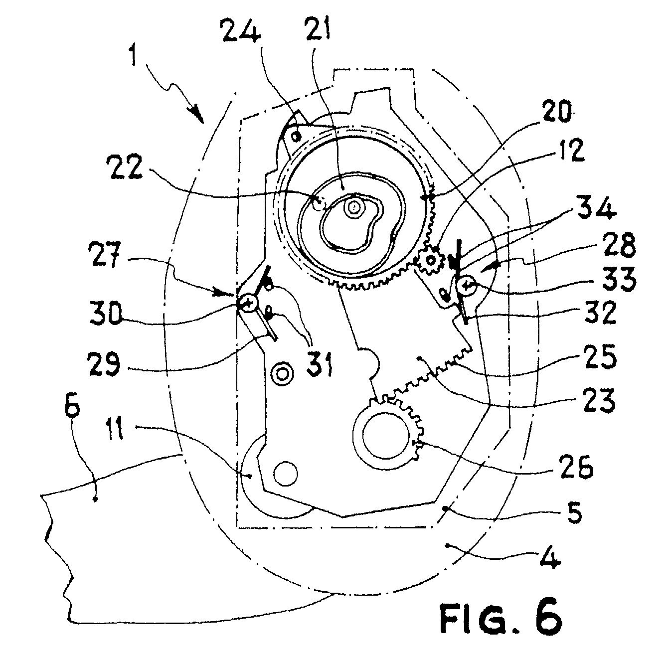
- Figure 6 shows a very schematic right side view of the mechanism, with the doll in the seated position, with one of the oscillating levers removed in order to appreciate the side channel of the central wheel.
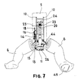
- Figure 7 shows a front view of the mechanism and the doll's legs.
- Figure 8 shows a schematic sectional view of the mechanism, with the doll in the laying down position.
- Figure 9 shows a schematic sectional view of the mechanism, with the doll in the seated position.
- Figure 10 shows a schematic sectional view of the mechanism with the doll laying down, but not in the extreme position of the oscillating levers.
- Figure 11 shows a view of the doll corresponding to the position of the mechanism illustrated in figure 10.
- Figure 12 shows a schematic of the doll's different electrical components.
- Figure 13 shows a very simplified electrical schematic of the supply to the motor.
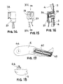
- Figure 14 shows a right side view of the microphone support.
- Figure 15 shows a front view of the microphone support.
- Figure 16 shows a left side sectional view of the microphone support.
- Figure 17 shows a side view of the doll's right leg, with a partial sectional view to illustrate the location of the batteries.
- Figure 18 shows a detailed plant view of the area of the articulation of the leg represented in figure 17.
-
- In said figures, the number references correspond to the following parts and elements:
- 1.
- Doll
- 2.
- Trunk
- 3.
- Material wrapping
- 4.
- Foam rubber
- 5.
- Mechanism
- 6.
- Legs
- 7.
- Arms
- 8.
- Head
- 9.
- Head motion device (8)
- 10.
- Mechanism plates
- 11.
- Electrical motor
- 12.
- Central gear
- 13.
- Drive pulley
- 14.
- Following pulley
- 15.
- Belt
- 16.
- Intermediate wheel
- 17.
- Following pulley gear
- 18.
- Central gear wheel
- 19.
- Intermediate gear
- 20.
- Central wheel
- 21.
- Channels
- 22.
- Knobs
- 23.
- Oscillating levers
- 24.
- Articulation axle
- 25.
- Oscillating toothed area
- 26.
- Toothed circular area
- 27.
- Off switch in laying down position
- 28.
- Off switch in seated position
- 29.
- Laying down stop wire
- 30.
- Laying down stop axle
- 31.
- Laying down stop rivets
- 32.
- Seated stop wire
- 33.
- Seated stop axle
- 34.
- Seated stop rivets
- 35.
- Oscillating lever port (23)
- 36.
- Microphone
- 37.
- Sensor support
- 38.
- Groove
- 39.
- Frontal opening
- 40.
- Main switch
- 41.
- Loudspeaker
- 42
- . Batteries
- 43.
- Electronic board
- 44.
- Cut axle
- 45.
- Battery cover
- 46.
- Lower dish
- 47.
- Cross axle
- 48.
- Upper dish
- 49.
- Dish axle
- 50.
- Dish port
- 51.
- Dish stop
- 52.
- Main relay
- 53.
- Common switch
- 54.
- Closing switch
- 55.
- Alternative relay
- 56.
- Alternative switch
- As can be seen in figures 1, 2, 3 and 4, the doll (1) object of the invention presents a trunk (2) constituted by a material wrapping (3) stuffed with foam rubber (4) which houses in its interior the mechanism (5), to which the legs (6) are united rotationally. The arms (7) do not move and they display a structure similar to that of the trunk (2) while the head (8) is united to it by means of a motion device (9) which will be described appropriately.
- The mechanism (5) is shown in figures 5, 6 and 7 and it basically consists of two mechanism plates (10) between which an electrical motor (11) is mounted which activates a central gear (12) by means of a drive pulley (13) attached to the shaft of the electrical motor (11), a following pulley (14), both connected by a belt (15), an intermediate wheel (16) which receives its movement from a following pulley gear (17) united to the following pulley (14) and a central gear wheel (18) united to the central gear (12) which receives its movement from an intermediate gear (19) united to the intermediate wheel (16). Arranged so as to gear into the central gear (12) is a central wheel (20) that has on each one of its sides matching channels (21) where two knobs (22) are housed which have two oscillating levers (23) arranged at each side of the central wheel (20) and that can revolve around an articulation axle (24) located near the doll's shoulders. Each oscillating lever (23) ends in the part farthest from the articulation axle (24) in an oscillating toothed area (25) which gears into a toothed circular area (26) united rotationally to the legs (6), as will be described appropriately.
- In order to allow the movement of the oscillating levers (23) these have matching oscillating lever ports (35) through which the rotating shaft of the central wheel (20) passes.
- As can be seen in figures 5 and 6, assembled on the right side mechanism plate (10) is the unit of wheels and gears which constitute the reducer of the electrical motor (11), and assembled on the left side mechanism plate (10) there is an off switch in laying down position (27) consisting of a laying down stop wire (29) wound around a laying down stop axle (30) which rests elastically on two laying down stop rivets (31), as well as an off switch in seated position (28) consisting of a seated stop wire (32) wound around a seated stop axle (33) which rests elastically on two seated stop rivets (34). The off switches (27) (28) are connected electrically in series and through them, one of the motor's poles is fed, as can be seen in figure 13.
- As a detection element of exterior stimulations there is a microphone (36) inserted tightly into a sensor support (37), which has a groove (38) that secures the foam rubber body (4) and the material wrapping (3) and thus ensure the transmission of the slightest touch from any part of the doll's body to the microphone (36). A frontal opening (39) picks up the speech directly. In the example represented as a preferred embodiment, the shape of a heart has been given to the visible part of the sensor support (37). See figures 14, 15 and 16.
- Figure 12 shows the general schematic of connections of the different electrical components, consisting of a main switch (40), a loudspeaker (41) and a battery case (42), aside from the microphone (36) and the electric motor (11) already mentioned, all being connected to an electronic board (43).
- In figures 17 and 18 the cut axle (44) can be seen, which constitutes the element that allows to fasten, in a rotationally attached way, the legs (6) to the toothed circular areas (26), which is an absolutely conventional device. Other elements, also familiar to an expert in the field, have not been represented in an attempt to not complicate the description unnecessarily.
- The motion device (9) of the head (8) consists of a lower dish (46) attached flexibly to the mechanism (5) by a cross axle (47) to the surrounding of which is attached the material wrapping (3) that constitutes the doll's (1) trunk (2), and an upper dish (48) that rotates around a dish axle (49) fastened to the lower dish (46) on which it rests. The side movement of the upper dish (48), and the head (8) attached to it , is limited by the dish port (50) on the upper dish (48) wherein there is a dish stop (51) attached to the lower dish (46). By this means the head moves freely from front to back, as well as to both sides when the doll (1) lays down or sits up, constituting a simple and economical motion device. See figures 3 and 4.
- The operation of the doll object of the invention is the following:
- Once the main switch (40) has been activated, the doll will reach one of the two extreme positions, laying down or sitting up, and it will remain resting. This operation is produced as a consequence of the activation of a main relay (52) and the closing of a common switch (53) and a closing switch (54), with the electric motor (11) stopping when the doll reaches one of its extreme positions and the off switch in laying down position (27) or the off switch in seated position (28) is opened. See figure 13.
- When the conventional detection circuit housed in the electronic board (43) detects a signal coming from the microphone (36) as a consequence of an exterior sound or touch stimulation, the alternative relay (55) is activated, which upon closing the alternative switch (56) supplies energy to the electric motor (11) even though one of the off switches (27) (28) remains open because of the doll being in one of its extreme laying down or seated positions. This energizing of the electric motor (11) is produced in the form of impulses of 2 seconds of duration and simultaneously unintelligible sounds are emitted from the loudspeaker (41).
- In figure 8 can be seen a schematic of the mechanism (5) when the doll (1) is in its laying down position. The oscillating lever (23) has caused the off switch in laying down position (27) to open, by separating the laying down stop wire (29) from one of the laying down stop rivets (31), consequently interrupting the supply to the electric motor (11). The doll (1) will not be able to come out of this position unless it is as a consequence of the activation of the microphone (36) by means of an exterior sound or touch stimulation. Usually, the two second motor impulse produced will be insufficient for the movement of the oscillating lever (23) to withdraw sufficiently to allow the closing of the off switch in laying down position (27) which will thus require a series of successive stimulations until the closing of this contact is produced, at which time the supply to the electric motor (11) will not cease until the doll (1) reaches the position shown in figure 9 and the oscillating lever (23) causes the opening of the off switch in seated position (28). In this way it is simulated that the doll (1) does not respond immediately to the exterior stimulations, introducing into its behavior a pseudo random response.
- The position of the two oscillating levers (23) with respect to the mechanism plates (10) is the same for the extreme positions represented in figures 8 and 9 but, by means of an adequate design of the channels (21) of the central wheel (20), a perceptible lag can be attained in its movement. Thus, it has been established that during the laying down operation, it is advantageous that one of the legs, the left one in the example at hand, is kept behind. This, and also since in this leg there is only one battery instead of the two that are in the right leg, causes a destabilized fall, simulating that during the doll's (1) operation of laying down, it raises one leg to maintain a certain balance. At this time, both off switches (27) (28) are closed, since the doll has not reached its extreme position. See figures 10 and 11.
- Likewise, to obtain a greater realism, it can be observed in figures 1 and 2 that the doll (1) lays down with its legs together, but it separates them when it sits up. This is attained simply with a downward and slightly backward inclination of the rotating axles of the toothed circular areas (26) and legs (6), as can be seen in figure 7, where the doll has been represented in a seated position with its legs (6) open.
- The battery (42) case in the legs (6) is conventional, being possible to substitute the batteries after opening a battery cover (45) located at the base of the doll's (1) feet, as shown in figure 17.
Claims (6)
- Doll (1) that reacts to the voice and to caressing by laying down or sitting up, consisting of a trunk (2) that has passive arms (7) and head (8) as well as flexible legs (6), characterized by having:an electric motor (11), for activation, that turns in only one direction,control means for shutting off the electric motor (11), consisting of an off switch in laying down position (27) and an off switch in seated position (28) looped in series to the electric motor (11), so that the supply circuit to the electric motor (11) opens when the doll (1) reaches the extreme positions of laying down or sitting up,control means for start-up of the electric motor (11) consisting of a microphone (36) capable of detecting both the sound of speech as well as that produced by touching any part of the doll (1), connected to an electronic board (43) susceptible of activating the electric motor (11) independently of the circuit that comprises the off switch in seated position (28) and the off switch in laying down position (27),means of motion of the trunk (2) with respect to the legs (6).
- Doll (1) that reacts to the voice and to caressing by laying down or sitting up, according to claim 1, characterized in that the microphone (36) is inserted tightly inside a sensor support (37) having a groove (38) arranged so as to secure the foam rubber body (4) contained in a material wrapping (3) that constitutes the trunk (2) of the doll (1).
- Doll (1) that reacts to the voice and to caressing by laying down or sitting up, according to claim 1, characterized in that the means of motion of the trunk (2) with respect to the legs (6) consist of a mechanism (5) that comprises two mechanism plates (10) between which the electric motor (11) is attached, which by means of a reducer activates a central wheel (20) that has on each one of its sides matching channels (21), where a pair of knobs (22) are housed which have two oscillating levers (23) arranged at each side of the central wheel (20) and that can rotate around an articulation axle (24) arranged near the doll's shoulders, with each oscillating lever (23) ending on its side opposite to the articulation point in an oscillating toothed area (25) which gears into a toothed circular area (26) united rotationally to the legs (6) of the doll (1).
- Doll (1) that reacts to the voice and to caressing by laying down or sitting up, according to claim 3, characterized in that the reducer consists of a drive pulley (13) attached to the electric motor's (11) axle on which a belt (15) is connected which in turn transmits the movement to a following pulley (14) attached to a following pulley gear (17) that gears into an intermediate wheel (16) that has an intermediate gear (19) which gears into a central gear wheel (18) attached to a central gear (12) which in turn gears into the mentioned central wheel (20).
- Doll (1) that reacts to the voice and to caressing by laying down or sitting up, according to claim 1, characterized in that the batteries (42) needed to supply energy to the electric motor (11) are located inside the doll's (1) legs (6), in order that these, being heavier than the trunk (2), tend to remain motionless resting on the floor, being the doll's (1) trunk (2) what moves in one or the other direction until reaching the laying down position or the sitting up position.
- Doll (1) that reacts to the voice and to caressing by laying down or sitting up, according to claim 1, characterized in that arranged on the doll's (1) trunk (2) there is a head motion device (9) consisting of a lower dish (46) attached flexibly to the mechanism (5) by a cross axle (47) to the surrounding of which is attached the material wrapping (3) that constitutes the exterior of the doll's (1) trunk (2), and an upper dish (48) that rotates around a dish axle (49) fastened to the lower dish (46) on which it rests, limiting the sideways movement of the upper dish (48) to the width of a dish port (50) appearing on the upper dish (48), wherein there is a dish stop (51) attached to the lower dish (46).
Applications Claiming Priority (2)
| Application Number | Priority Date | Filing Date | Title |
|---|---|---|---|
| ES200100690A ES2201856B1 (en) | 2001-03-23 | 2001-03-23 | DOLL THAT REACTS TO VOICE AND CARE, LIKING OR SITTING. |
| ES200100690 | 2001-03-23 |
Publications (3)
| Publication Number | Publication Date |
|---|---|
| EP1243296A2 true EP1243296A2 (en) | 2002-09-25 |
| EP1243296A3 EP1243296A3 (en) | 2003-08-13 |
| EP1243296B1 EP1243296B1 (en) | 2006-12-06 |
Family
ID=8497206
Family Applications (1)
| Application Number | Title | Priority Date | Filing Date |
|---|---|---|---|
| EP01500255A Expired - Lifetime EP1243296B1 (en) | 2001-03-23 | 2001-10-25 | Doll that reacts to the voice and to being caressed |
Country Status (6)
| Country | Link |
|---|---|
| US (1) | US6666744B2 (en) |
| EP (1) | EP1243296B1 (en) |
| AT (1) | ATE347420T1 (en) |
| DE (1) | DE60125014T2 (en) |
| ES (1) | ES2201856B1 (en) |
| PT (1) | PT1243296E (en) |
Families Citing this family (15)
| Publication number | Priority date | Publication date | Assignee | Title |
|---|---|---|---|---|
| US7695341B1 (en) * | 2002-11-27 | 2010-04-13 | Hasbro, Inc. | Electromechanical toy |
| US6773327B1 (en) | 2002-02-12 | 2004-08-10 | Hasbro, Inc. | Apparatus for actuating a toy |
| AU156270S (en) | 2003-04-01 | 2004-08-24 | Tomy Co Ltd | A doll |
| US6843703B1 (en) | 2003-04-30 | 2005-01-18 | Hasbro, Inc. | Electromechanical toy |
| USD560732S1 (en) * | 2006-06-05 | 2008-01-29 | Wallis Mandi F | Biblical baby doll |
| USD567305S1 (en) * | 2007-06-20 | 2008-04-22 | Man Kit Hui | Doll |
| USD567306S1 (en) * | 2007-06-26 | 2008-04-22 | Man Kit Hui | Doll |
| USD567307S1 (en) * | 2007-06-26 | 2008-04-22 | Man Kit Hui | Doll |
| USD589571S1 (en) * | 2007-06-26 | 2009-03-31 | Man Kit Hui | Doll |
| CN101417180A (en) * | 2007-10-26 | 2009-04-29 | 鹏智科技(深圳)有限公司 | Toy of human shape |
| JP6443420B2 (en) * | 2016-10-04 | 2018-12-26 | トヨタ自動車株式会社 | Voice recognition device |
| WO2019213260A1 (en) * | 2018-05-01 | 2019-11-07 | Misty Robotics, Inc. | Robot neck mechanism |
| USD948636S1 (en) * | 2020-04-14 | 2022-04-12 | Nanjing Wulin Economic Information Consulting Limited | Doll with outfit |
| CN111588240B (en) * | 2020-05-29 | 2025-01-07 | 厦门构用科技有限公司 | A buttocks model and model prop capable of opening and closing |
| USD898131S1 (en) * | 2020-06-12 | 2020-10-06 | Mingming Liu | Baby doll |
Citations (1)
| Publication number | Priority date | Publication date | Assignee | Title |
|---|---|---|---|---|
| US4249338A (en) | 1979-11-26 | 1981-02-10 | Howard Wexler | Doll with sound generator and plural switch means |
Family Cites Families (10)
| Publication number | Priority date | Publication date | Assignee | Title |
|---|---|---|---|---|
| US2596491A (en) * | 1950-08-04 | 1952-05-13 | Kinberg Benjamin | Doll |
| US2990646A (en) * | 1954-02-10 | 1961-07-04 | Berger Christian Dean | Sound-actuated doll |
| US2906059A (en) * | 1954-02-10 | 1959-09-29 | Christian D Berger | Doll with sound-actuated moving parts |
| US3036404A (en) * | 1960-05-02 | 1962-05-29 | Berger Christian Dean | Sound-controllable toy |
| US3568362A (en) * | 1969-02-14 | 1971-03-09 | Remco Ind Inc | Animated doll |
| US3583098A (en) * | 1969-06-02 | 1971-06-08 | Mattel Inc | Dancing walking doll |
| US5236385A (en) * | 1992-02-07 | 1993-08-17 | California R&D Center, Inc. | Mechanical doll assembly capable of simulating sleep |
| ES2147534B1 (en) * | 1998-11-30 | 2001-04-16 | Onilco Innovacion Sa | DOLL THAT MOVES WITH EMPTY STEP AND FALL MOVEMENTS AND RECOVERY OF VERTICALITY. |
| US6095887A (en) * | 1998-02-24 | 2000-08-01 | Onilco Innovacion S.A. | Doll capable of walking with unsteady steps and with falling and upright recovery motions |
| US6506095B1 (en) * | 2002-01-30 | 2003-01-14 | Lund & Company | Animated toy doll |
-
2001
- 2001-03-23 ES ES200100690A patent/ES2201856B1/en not_active Expired - Fee Related
- 2001-10-25 DE DE60125014T patent/DE60125014T2/en not_active Expired - Fee Related
- 2001-10-25 PT PT01500255T patent/PT1243296E/en unknown
- 2001-10-25 EP EP01500255A patent/EP1243296B1/en not_active Expired - Lifetime
- 2001-10-25 AT AT01500255T patent/ATE347420T1/en not_active IP Right Cessation
- 2001-11-14 US US10/003,760 patent/US6666744B2/en not_active Expired - Fee Related
Patent Citations (1)
| Publication number | Priority date | Publication date | Assignee | Title |
|---|---|---|---|---|
| US4249338A (en) | 1979-11-26 | 1981-02-10 | Howard Wexler | Doll with sound generator and plural switch means |
Also Published As
| Publication number | Publication date |
|---|---|
| US20020137426A1 (en) | 2002-09-26 |
| PT1243296E (en) | 2007-03-30 |
| US6666744B2 (en) | 2003-12-23 |
| ATE347420T1 (en) | 2006-12-15 |
| EP1243296B1 (en) | 2006-12-06 |
| ES2201856A1 (en) | 2004-03-16 |
| DE60125014D1 (en) | 2007-01-18 |
| DE60125014T2 (en) | 2007-07-05 |
| ES2201856B1 (en) | 2005-05-16 |
| EP1243296A3 (en) | 2003-08-13 |
Similar Documents
| Publication | Publication Date | Title |
|---|---|---|
| US6666744B2 (en) | Doll that reacts to the voice and to caressing by laying down or sitting up | |
| US5820441A (en) | Animated doll | |
| US6203395B1 (en) | Electronic activity center | |
| US7431629B1 (en) | Electromechanical toy | |
| EP1022039A2 (en) | Variable performance toys | |
| WO1996025206A1 (en) | Self-propelled musical toy ball | |
| US6200193B1 (en) | Stimulus-responsive novelty device | |
| US7942720B1 (en) | Animated “peek-a-boo” stuffed toy creature | |
| AU731294B2 (en) | Toy having jumping action | |
| US20060228982A1 (en) | Interactive figure | |
| US6386937B1 (en) | Magnetically coupled toy apparatus | |
| US6547630B2 (en) | Heart shaped novelty device | |
| US20070224909A1 (en) | Child Receiving Device with Child Entertainment System | |
| CA2528801C (en) | Projected implement entertainment device | |
| WO2024119167A1 (en) | Interactive motorized rotating toy | |
| WO2010045268A2 (en) | Electronic interactive toy | |
| US20150070143A1 (en) | Novelty Door Knocker with Audio Playback | |
| JP2001334073A (en) | Amusement device | |
| US7762866B2 (en) | Interactive rocking cradle and doll | |
| US20050095948A1 (en) | Children's entertainment and development toy | |
| US20050142984A1 (en) | Toy actuation device | |
| US20100130095A1 (en) | Food chewing assembly for doll | |
| US3483655A (en) | Coacting doll and cradle,including electric sounder and time delay device | |
| JP3586305B2 (en) | Stuffed toys | |
| AU706411B2 (en) | Animated doll |
Legal Events
| Date | Code | Title | Description |
|---|---|---|---|
| PUAI | Public reference made under article 153(3) epc to a published international application that has entered the european phase |
Free format text: ORIGINAL CODE: 0009012 |
|
| AK | Designated contracting states |
Kind code of ref document: A2 Designated state(s): AT BE CH CY DE DK ES FI FR GB GR IE IT LI LU MC NL PT SE TR |
|
| AX | Request for extension of the european patent |
Free format text: AL;LT;LV;MK;RO;SI |
|
| PUAL | Search report despatched |
Free format text: ORIGINAL CODE: 0009013 |
|
| AK | Designated contracting states |
Designated state(s): AT BE CH CY DE DK ES FI FR GB GR IE IT LI LU MC NL PT SE TR |
|
| AX | Request for extension of the european patent |
Extension state: AL LT LV MK RO SI |
|
| RAP1 | Party data changed (applicant data changed or rights of an application transferred) |
Owner name: FABRICAS AGRUPADAS DE MUNECAS DE ONIL, S.A. |
|
| 17P | Request for examination filed |
Effective date: 20040210 |
|
| AKX | Designation fees paid |
Designated state(s): AT BE CH CY DE DK ES FI FR GB GR IE IT LI LU MC NL PT SE TR |
|
| 17Q | First examination report despatched |
Effective date: 20050705 |
|
| GRAP | Despatch of communication of intention to grant a patent |
Free format text: ORIGINAL CODE: EPIDOSNIGR1 |
|
| GRAS | Grant fee paid |
Free format text: ORIGINAL CODE: EPIDOSNIGR3 |
|
| GRAA | (expected) grant |
Free format text: ORIGINAL CODE: 0009210 |
|
| AK | Designated contracting states |
Kind code of ref document: B1 Designated state(s): AT BE CH CY DE DK ES FI FR GB GR IE IT LI LU MC NL PT SE TR |
|
| PG25 | Lapsed in a contracting state [announced via postgrant information from national office to epo] |
Ref country code: AT Free format text: LAPSE BECAUSE OF FAILURE TO SUBMIT A TRANSLATION OF THE DESCRIPTION OR TO PAY THE FEE WITHIN THE PRESCRIBED TIME-LIMIT Effective date: 20061206 Ref country code: CH Free format text: LAPSE BECAUSE OF FAILURE TO SUBMIT A TRANSLATION OF THE DESCRIPTION OR TO PAY THE FEE WITHIN THE PRESCRIBED TIME-LIMIT Effective date: 20061206 Ref country code: DK Free format text: LAPSE BECAUSE OF FAILURE TO SUBMIT A TRANSLATION OF THE DESCRIPTION OR TO PAY THE FEE WITHIN THE PRESCRIBED TIME-LIMIT Effective date: 20061206 Ref country code: LI Free format text: LAPSE BECAUSE OF FAILURE TO SUBMIT A TRANSLATION OF THE DESCRIPTION OR TO PAY THE FEE WITHIN THE PRESCRIBED TIME-LIMIT Effective date: 20061206 Ref country code: FI Free format text: LAPSE BECAUSE OF FAILURE TO SUBMIT A TRANSLATION OF THE DESCRIPTION OR TO PAY THE FEE WITHIN THE PRESCRIBED TIME-LIMIT Effective date: 20061206 |
|
| REG | Reference to a national code |
Ref country code: GB Ref legal event code: FG4D |
|
| REG | Reference to a national code |
Ref country code: CH Ref legal event code: EP |
|
| REG | Reference to a national code |
Ref country code: IE Ref legal event code: FG4D |
|
| REF | Corresponds to: |
Ref document number: 60125014 Country of ref document: DE Date of ref document: 20070118 Kind code of ref document: P |
|
| PG25 | Lapsed in a contracting state [announced via postgrant information from national office to epo] |
Ref country code: SE Free format text: LAPSE BECAUSE OF FAILURE TO SUBMIT A TRANSLATION OF THE DESCRIPTION OR TO PAY THE FEE WITHIN THE PRESCRIBED TIME-LIMIT Effective date: 20070306 |
|
| PG25 | Lapsed in a contracting state [announced via postgrant information from national office to epo] |
Ref country code: ES Free format text: LAPSE BECAUSE OF FAILURE TO SUBMIT A TRANSLATION OF THE DESCRIPTION OR TO PAY THE FEE WITHIN THE PRESCRIBED TIME-LIMIT Effective date: 20070317 |
|
| REG | Reference to a national code |
Ref country code: PT Ref legal event code: SC4A Free format text: AVAILABILITY OF NATIONAL TRANSLATION Effective date: 20070306 |
|
| REG | Reference to a national code |
Ref country code: CH Ref legal event code: PL |
|
| ET | Fr: translation filed | ||
| REG | Reference to a national code |
Ref country code: PT Ref legal event code: PD4A Owner name: FABRICAS AGRUPADAS DE MUNECAS DE ONIL SOCIEDAD, ES Effective date: 20070924 Ref country code: PT Ref legal event code: PC4A Owner name: INVERSIONES FADIVER, SA, ES Effective date: 20070924 |
|
| PLBE | No opposition filed within time limit |
Free format text: ORIGINAL CODE: 0009261 |
|
| STAA | Information on the status of an ep patent application or granted ep patent |
Free format text: STATUS: NO OPPOSITION FILED WITHIN TIME LIMIT |
|
| 26N | No opposition filed |
Effective date: 20070907 |
|
| BECA | Be: change of holder's address |
Owner name: FABRICAS AGRUPADAS DE MUNECAS DE ONIL, S.A.C/. SAN Effective date: 20061206 |
|
| BECH | Be: change of holder |
Owner name: FABRICAS AGRUPADAS DE MUNECAS DE ONIL, S.A. Effective date: 20061206 |
|
| BECN | Be: change of holder's name |
Owner name: FABRICAS AGRUPADAS DE MUNECAS DE ONIL, S.A.C/. SAN Effective date: 20071122 |
|
| REG | Reference to a national code |
Ref country code: GB Ref legal event code: 732E |
|
| PGFP | Annual fee paid to national office [announced via postgrant information from national office to epo] |
Ref country code: DE Payment date: 20071025 Year of fee payment: 7 Ref country code: LU Payment date: 20071025 Year of fee payment: 7 Ref country code: NL Payment date: 20071023 Year of fee payment: 7 |
|
| NLS | Nl: assignments of ep-patents |
Owner name: INVERSIONES FADIVER, S.A. Effective date: 20071203 |
|
| NLT1 | Nl: modifications of names registered in virtue of documents presented to the patent office pursuant to art. 16 a, paragraph 1 |
Owner name: FABRICAS AGRUPADAS DE MUNECAS DE ONIL, S.A. |
|
| PGFP | Annual fee paid to national office [announced via postgrant information from national office to epo] |
Ref country code: IT Payment date: 20071031 Year of fee payment: 7 |
|
| PGFP | Annual fee paid to national office [announced via postgrant information from national office to epo] |
Ref country code: BE Payment date: 20071213 Year of fee payment: 7 |
|
| PG25 | Lapsed in a contracting state [announced via postgrant information from national office to epo] |
Ref country code: GR Free format text: LAPSE BECAUSE OF FAILURE TO SUBMIT A TRANSLATION OF THE DESCRIPTION OR TO PAY THE FEE WITHIN THE PRESCRIBED TIME-LIMIT Effective date: 20070307 |
|
| PGFP | Annual fee paid to national office [announced via postgrant information from national office to epo] |
Ref country code: FR Payment date: 20071025 Year of fee payment: 7 Ref country code: GB Payment date: 20071024 Year of fee payment: 7 |
|
| REG | Reference to a national code |
Ref country code: FR Ref legal event code: TP Ref country code: FR Ref legal event code: CD |
|
| PG25 | Lapsed in a contracting state [announced via postgrant information from national office to epo] |
Ref country code: MC Free format text: LAPSE BECAUSE OF NON-PAYMENT OF DUE FEES Effective date: 20071031 |
|
| PGFP | Annual fee paid to national office [announced via postgrant information from national office to epo] |
Ref country code: PT Payment date: 20071018 Year of fee payment: 7 |
|
| PG25 | Lapsed in a contracting state [announced via postgrant information from national office to epo] |
Ref country code: IE Free format text: LAPSE BECAUSE OF NON-PAYMENT OF DUE FEES Effective date: 20071025 |
|
| BERE | Be: lapsed |
Owner name: FABRICAS AGRUPADAS DE MUNECAS DE ONIL, S.A. Effective date: 20081031 |
|
| REG | Reference to a national code |
Ref country code: PT Ref legal event code: MM4A Free format text: LAPSE DUE TO NON-PAYMENT OF FEES Effective date: 20090427 |
|
| GBPC | Gb: european patent ceased through non-payment of renewal fee |
Effective date: 20081025 |
|
| NLV4 | Nl: lapsed or anulled due to non-payment of the annual fee |
Effective date: 20090501 |
|
| REG | Reference to a national code |
Ref country code: FR Ref legal event code: ST Effective date: 20090630 |
|
| PG25 | Lapsed in a contracting state [announced via postgrant information from national office to epo] |
Ref country code: NL Free format text: LAPSE BECAUSE OF NON-PAYMENT OF DUE FEES Effective date: 20090501 |
|
| PG25 | Lapsed in a contracting state [announced via postgrant information from national office to epo] |
Ref country code: IT Free format text: LAPSE BECAUSE OF NON-PAYMENT OF DUE FEES Effective date: 20081025 Ref country code: CY Free format text: LAPSE BECAUSE OF FAILURE TO SUBMIT A TRANSLATION OF THE DESCRIPTION OR TO PAY THE FEE WITHIN THE PRESCRIBED TIME-LIMIT Effective date: 20061206 Ref country code: DE Free format text: LAPSE BECAUSE OF NON-PAYMENT OF DUE FEES Effective date: 20090501 Ref country code: PT Free format text: LAPSE BECAUSE OF NON-PAYMENT OF DUE FEES Effective date: 20090427 |
|
| PG25 | Lapsed in a contracting state [announced via postgrant information from national office to epo] |
Ref country code: TR Free format text: LAPSE BECAUSE OF FAILURE TO SUBMIT A TRANSLATION OF THE DESCRIPTION OR TO PAY THE FEE WITHIN THE PRESCRIBED TIME-LIMIT Effective date: 20061206 Ref country code: BE Free format text: LAPSE BECAUSE OF NON-PAYMENT OF DUE FEES Effective date: 20081031 |
|
| PG25 | Lapsed in a contracting state [announced via postgrant information from national office to epo] |
Ref country code: FR Free format text: LAPSE BECAUSE OF NON-PAYMENT OF DUE FEES Effective date: 20081031 |
|
| PG25 | Lapsed in a contracting state [announced via postgrant information from national office to epo] |
Ref country code: GB Free format text: LAPSE BECAUSE OF NON-PAYMENT OF DUE FEES Effective date: 20081025 |
|
| PG25 | Lapsed in a contracting state [announced via postgrant information from national office to epo] |
Ref country code: LU Free format text: LAPSE BECAUSE OF NON-PAYMENT OF DUE FEES Effective date: 20081025 |