EP1243244A1 - Delivery device with adjustable jet orientation - Google Patents
Delivery device with adjustable jet orientation Download PDFInfo
- Publication number
- EP1243244A1 EP1243244A1 EP02006157A EP02006157A EP1243244A1 EP 1243244 A1 EP1243244 A1 EP 1243244A1 EP 02006157 A EP02006157 A EP 02006157A EP 02006157 A EP02006157 A EP 02006157A EP 1243244 A1 EP1243244 A1 EP 1243244A1
- Authority
- EP
- European Patent Office
- Prior art keywords
- delivery device
- ejector
- cam
- annular
- ring
- Prior art date
- Legal status (The legal status is an assumption and is not a legal conclusion. Google has not performed a legal analysis and makes no representation as to the accuracy of the status listed.)
- Granted
Links
- 230000033001 locomotion Effects 0.000 claims abstract description 19
- 239000007788 liquid Substances 0.000 claims abstract description 9
- 239000013013 elastic material Substances 0.000 claims abstract description 8
- 238000006073 displacement reaction Methods 0.000 claims description 14
- 239000012530 fluid Substances 0.000 claims description 7
- 229920001971 elastomer Polymers 0.000 claims description 4
- 239000000806 elastomer Substances 0.000 claims description 3
- XLYOFNOQVPJJNP-UHFFFAOYSA-N water Substances O XLYOFNOQVPJJNP-UHFFFAOYSA-N 0.000 description 10
- 238000010276 construction Methods 0.000 description 3
- 238000012423 maintenance Methods 0.000 description 3
- 230000000694 effects Effects 0.000 description 2
- 238000004519 manufacturing process Methods 0.000 description 2
- 239000000463 material Substances 0.000 description 2
- 238000012986 modification Methods 0.000 description 2
- 230000004048 modification Effects 0.000 description 2
- 238000005507 spraying Methods 0.000 description 2
- 230000015572 biosynthetic process Effects 0.000 description 1
- 238000004140 cleaning Methods 0.000 description 1
- 238000001514 detection method Methods 0.000 description 1
- 230000005489 elastic deformation Effects 0.000 description 1
- 238000004299 exfoliation Methods 0.000 description 1
- 238000009434 installation Methods 0.000 description 1
- 229940075473 medical gases Drugs 0.000 description 1
- 230000010355 oscillation Effects 0.000 description 1
- 230000003534 oscillatory effect Effects 0.000 description 1
- 238000004659 sterilization and disinfection Methods 0.000 description 1
Images



Classifications
-
- A—HUMAN NECESSITIES
- A61—MEDICAL OR VETERINARY SCIENCE; HYGIENE
- A61H—PHYSICAL THERAPY APPARATUS, e.g. DEVICES FOR LOCATING OR STIMULATING REFLEX POINTS IN THE BODY; ARTIFICIAL RESPIRATION; MASSAGE; BATHING DEVICES FOR SPECIAL THERAPEUTIC OR HYGIENIC PURPOSES OR SPECIFIC PARTS OF THE BODY
- A61H33/00—Bathing devices for special therapeutic or hygienic purposes
- A61H33/02—Bathing devices for use with gas-containing liquid, or liquid in which gas is led or generated, e.g. carbon dioxide baths
- A61H33/027—Gas-water mixing nozzles therefor
-
- A—HUMAN NECESSITIES
- A61—MEDICAL OR VETERINARY SCIENCE; HYGIENE
- A61H—PHYSICAL THERAPY APPARATUS, e.g. DEVICES FOR LOCATING OR STIMULATING REFLEX POINTS IN THE BODY; ARTIFICIAL RESPIRATION; MASSAGE; BATHING DEVICES FOR SPECIAL THERAPEUTIC OR HYGIENIC PURPOSES OR SPECIFIC PARTS OF THE BODY
- A61H2201/00—Characteristics of apparatus not provided for in the preceding codes
- A61H2201/12—Driving means
- A61H2201/1207—Driving means with electric or magnetic drive
- A61H2201/1215—Rotary drive
-
- A—HUMAN NECESSITIES
- A61—MEDICAL OR VETERINARY SCIENCE; HYGIENE
- A61H—PHYSICAL THERAPY APPARATUS, e.g. DEVICES FOR LOCATING OR STIMULATING REFLEX POINTS IN THE BODY; ARTIFICIAL RESPIRATION; MASSAGE; BATHING DEVICES FOR SPECIAL THERAPEUTIC OR HYGIENIC PURPOSES OR SPECIFIC PARTS OF THE BODY
- A61H2201/00—Characteristics of apparatus not provided for in the preceding codes
- A61H2201/14—Special force transmission means, i.e. between the driving means and the interface with the user
- A61H2201/1418—Cam
-
- A—HUMAN NECESSITIES
- A61—MEDICAL OR VETERINARY SCIENCE; HYGIENE
- A61H—PHYSICAL THERAPY APPARATUS, e.g. DEVICES FOR LOCATING OR STIMULATING REFLEX POINTS IN THE BODY; ARTIFICIAL RESPIRATION; MASSAGE; BATHING DEVICES FOR SPECIAL THERAPEUTIC OR HYGIENIC PURPOSES OR SPECIFIC PARTS OF THE BODY
- A61H2201/00—Characteristics of apparatus not provided for in the preceding codes
- A61H2201/16—Physical interface with patient
- A61H2201/1657—Movement of interface, i.e. force application means
- A61H2201/1676—Pivoting
- A61H2201/1678—Means for angularly oscillating massage elements
-
- A—HUMAN NECESSITIES
- A61—MEDICAL OR VETERINARY SCIENCE; HYGIENE
- A61H—PHYSICAL THERAPY APPARATUS, e.g. DEVICES FOR LOCATING OR STIMULATING REFLEX POINTS IN THE BODY; ARTIFICIAL RESPIRATION; MASSAGE; BATHING DEVICES FOR SPECIAL THERAPEUTIC OR HYGIENIC PURPOSES OR SPECIFIC PARTS OF THE BODY
- A61H33/00—Bathing devices for special therapeutic or hygienic purposes
- A61H33/60—Components specifically designed for the therapeutic baths of groups A61H33/00
- A61H33/601—Inlet to the bath
- A61H33/6021—Nozzles
- A61H33/6063—Specifically adapted for fitting in bathtub walls
Definitions
- the present invention relates to a delivery device with adjustable position ejector, particularly adapted to be used for hydro-massage baths.
- Each delivery device is provided with an adjustable position ejector allowing to direct the flow at will of the user.
- the ejectors can be oriented manually by the user and this has the drawback of needing continuous interventions by the user any time he wants to modify the jet direction.
- articulation means consisting of two or more mechanical elements pivotally coupled for instance through ball joints, connecting each ejector to the corresponding water supply tube.
- Another drawback consists also in that, in view of of the complex construction of said articulation means, the operational reliability of the delivery device is rather low and the user is obliged to frequent maintenance interventions.
- Another drawback consists in that, since said articulation means comprise several pieces pivotally connected to each other, they show even deep gaps and sometimes undercut areas that being in contact with water cause deposit of organic residues coming from exfoliation of the skin of the person undergoing the hydro-massage treatment.
- a last but not least drawback consists in that use of said articulation means increases the dimensions of each delivery device and this generally causes greater overall dimensions of the bath and assembling and disassembling difficulties during installation and/or any maintenance operation.
- the present invention aims to overcome said drawbacks.
- an object of the present invention is to provide a delivery device that for adjusting the ejector position does not require use of articulation means consisting of two or more mechanical elements pivotally connected to each other.
- Another object consists in that servo-assisted actuators can be easily associated to the delivery device of the invention for adjusting the spout direction and flow rate.
- a further object is that the delivery device of the invention is less prone to deposit of organic residues in comparison with the known devices.
- Another object is that the delivery device of the invention has a greater reliability of operation in comparison with equivalent devices of known type.
- a last but not least object is that the delivery device of the invention has also lower dimensions relative to equivalent known devices.
- a delivery device particularly adapted to be used in hydro-massage baths that according to the main claim comprises at least an ejector hydraulically connected to at least an outer duct supplying a liquid to be delivered and mechanically connected by interposition of articulation means to driving means adapted to put it in motion, and is characterised in that said articulation means comprise at least an annular surface made of a yielding and elastic material arranged between a first annular collar defining the outlet of said device and a second annular collar mechanically connected internally to said ejector and externally to said driving means.
- the annular surface, the first collar and the second collar belong to a single tubular element fully made of yielding and elastic material, provided with a first inlet way for connection of an outer duct supplying the liquid to be delivered and a second inlet way for connection of an outer duct supplying a gaseous fluid.
- the delivery device comprises also shutting means to intercept and regulate the flow of liquid to be delivered through said device.
- interception and regulation means comprise a pusher put in motion by displacement means, acting outside on the tubular element so as to modify the passage section by elastic deformation.
- the displacement means of said pusher and the driving means of the ejector generally comprise cam means associated to an electric motor.
- cam means are associated to the ejector, said cam means being in turn associated to corresponding driving means arranged at right angles to each other allowing to traverse the ejector along planes perpendicular to each other.
- Both motors of the driving means are electrically connected to an electronic control board that combining properly the traverse motion of both means generates a rotary motion of the ejector with space development.
- the same electronic control board is electrically connected to the displacement means to vary the delivery of the ejector from the closed position to the maximum opening position.
- the delivery device of the invention allows a greater hygienic condition of the hydro-massage baths and requires less maintenance and cleaning interventions.
- the delivery device has also lower dimensions and costs in comparison with equivalent known delivery devices.
- the delivery device of the invention is shown in the isometric views of Figs. 1 to 3, where it is generally indicated with reference numeral 1, and also in Figs. 4 and 5 where it is shown in a partial sectional view.
- the delivery device 1 is particularly adapted to be used in hydro-massage baths and comprises an ejector 2 hydraulically connected to an outer duct C1 supplying a liquid to be delivered, which is mechanically connected through articulation means generally indicated with numeral 3 to driving units generally indicated with numeral 4 adapted to put it in motion.
- the articulation means 3 comprise an annular surface 5 made of yielding and elastic material, arranged between a first annular collar 6 defining the outlet 7 of the device and a second annular collar 8 mechanically connected internally to the ejector 2 and externally to said driving units 4.
- annular surface 5, the first collar 6 and the second collar 8 belong to a single tubular element 9 which is fully made of yielding and elastic material, preferably but not necessarily an elastomer such as rubber or its mixes.
- a first inlet way 10 for connection to an outer duct C1 supplying the liquid to be delivered, preferably water, and a second inlet way 11 for connection to an outer duct C2 supplying a gaseous fluid, are defined.
- gaseous fluid is preferably but not necessarily air, which could be replaced or integrated with medical gases of various type.
- Water entering through the first inlet way 10 is mixed with the gaseous fluid entering through the second inlet way 11 and goes out through the ejector 2 conveying it to the body of the person immersed in the bath.
- the tubular element 9 is removably received in a holding structure 12 constituting the body of the device 1 and used to fix the delivery device to the bath.
- the holding structure 12 is also used to support the driving units 4 for the articulation of the ejector 2, which are externally connected to the second annular collar 8 through an annular ring 13 that can be seen in greater detail in Figs. 7 and 8.
- annular ring 13 is provided with ring nuts 14, 15 arranged orthogonally to each other, each of them receiving the connection of one of the driving units 4.
- Each driving unit 4 comprises a cam 16, 17 provided with a screw 18, 19 of connection to the corresponding ring nut 14, 15 and having a shaped outline 16a, 17a, slidingly co-operating with a pin 20, 21 eccentrically arranged in a disc 22, 23 coupled to the shaft 24, 25 of a corresponding electrical motor 26, 27.
- each cam 16, 17 as already stated, is fixed to the annular ring 13, each cam transmits its displacement to the second annular collar 9 to which is connected and therefore to the ejector 2 that is nip inserted in the annular collar 9.
- Both motors 26, 27 are electrically connected to an electronic control board not shown in the drawings, which drives properly the speed of both motors, combines the oscillating motions of the ejector 2 so as to generate for said ejector 2 a curved space motion around the rotation centre O allowing to orient the spout in any direction desired by the user.
- control board it is possible to carry out the following steps: traverse ejector 2 on plane ⁇ ; traverse ejector 2 on plane ⁇ ; combine the two traverse motions so as to obtain a space rotary motion of the ejector 2; change the spraying position of the ejector setting it along different directions at choice of the user.
- the delivery device comprises also a pusher 40 that can be seen particularly in Fig. 4, acting externally on the tubular element 9 at a zone 9a of said element, comprised between the first inlet way 10 supplying water and the second inlet way 11 supplying the gaseous fluid.
- the pusher 40 is associated to a displacement unit generally indicated with 41, adapted to move it in a rectilinear direction along the lines opposite to each other indicated by arrow 42.
- the displacement unit 41 comprises a cam 43 on the inner profile 43a of which a pin 44 is slidingly contacted, belonging to a disc 45 fixed and caused to rotate by the shaft 46 of an electric motor 47.
- the cam 43 converts the rotary motion of shaft 46 of motor 47 in a vertical motion of pusher 40 causing the formation of the tubular element 9 at the contact zone 9a that can be deformed according to the configuration 9b when it is desired to intersect totally the flow through the ejector 2.
- Magnetic elements 48 are provided also in the disc 45, co-operating with fixed sensors to detect and define the position of pusher 40 and vary the flow rate of the ejector.
- connection of ejector 2 to the driving units 4 occurs without using mechanical articulation means consisting of two or more mechanical elements pivotally connected to each other because the single yielding element consists of the annular surface 5 made of elastomer.
- a delivery device is advantageously obtained warranting a greater hygienic condition, more reliable operation and less expensive in the manufacturing stage.
Landscapes
- Health & Medical Sciences (AREA)
- Public Health (AREA)
- Epidemiology (AREA)
- Pain & Pain Management (AREA)
- Physical Education & Sports Medicine (AREA)
- Rehabilitation Therapy (AREA)
- Life Sciences & Earth Sciences (AREA)
- Animal Behavior & Ethology (AREA)
- General Health & Medical Sciences (AREA)
- Veterinary Medicine (AREA)
- Massaging Devices (AREA)
- Jet Pumps And Other Pumps (AREA)
- Percussion Or Vibration Massage (AREA)
- Nozzles (AREA)
- Beans For Foods Or Fodder (AREA)
- Devices For Medical Bathing And Washing (AREA)
- Confectionery (AREA)
- Coating Apparatus (AREA)
Abstract
Description
- The present invention relates to a delivery device with adjustable position ejector, particularly adapted to be used for hydro-massage baths.
- It is well known that in the hydro-massage baths a plurality of delivery devices are provided, conveying to the body of the person immersed in the bath a flow of pressurised water to which air is added.
- Each delivery device is provided with an adjustable position ejector allowing to direct the flow at will of the user.
- The ejectors can be oriented manually by the user and this has the drawback of needing continuous interventions by the user any time he wants to modify the jet direction.
- Other versions intended for hydro-massage baths of high cost and therefore for professional use are also known, that still have the manual regulation of the spraying direction of the ejectors but allow a servo-assisted regulation of the delivered flow.
- Irrespective of the kind of hydro-massage baths, movement of the ejectors is obtained by articulation means consisting of two or more mechanical elements pivotally coupled for instance through ball joints, connecting each ejector to the corresponding water supply tube.
- All the known delivery devices therefore have a first drawback consisting of the complex construction of said articulation means.
- Consequently said delivery devices have also the further drawback of a high manufacturing cost and therefore a high selling price.
- Another drawback consists also in that, in view of of the complex construction of said articulation means, the operational reliability of the delivery device is rather low and the user is obliged to frequent maintenance interventions.
- Another drawback consists in that, since said articulation means comprise several pieces pivotally connected to each other, they show even deep gaps and sometimes undercut areas that being in contact with water cause deposit of organic residues coming from exfoliation of the skin of the person undergoing the hydro-massage treatment.
- This causes lower hygienic conditions during the treatment and the need to carry our regularly the disinfection of the bath and of the whole water delivery system.
- A last but not least drawback consists in that use of said articulation means increases the dimensions of each delivery device and this generally causes greater overall dimensions of the bath and assembling and disassembling difficulties during installation and/or any maintenance operation.
- The present invention aims to overcome said drawbacks.
- More particularly an object of the present invention is to provide a delivery device that for adjusting the ejector position does not require use of articulation means consisting of two or more mechanical elements pivotally connected to each other.
- Another object consists in that servo-assisted actuators can be easily associated to the delivery device of the invention for adjusting the spout direction and flow rate.
- A further object is that the delivery device of the invention is less prone to deposit of organic residues in comparison with the known devices.
- Another object is that the delivery device of the invention has a greater reliability of operation in comparison with equivalent devices of known type.
- A last but not least object is that the delivery device of the invention has also lower dimensions relative to equivalent known devices.
- The foregoing objects are attained by providing a delivery device particularly adapted to be used in hydro-massage baths that according to the main claim comprises at least an ejector hydraulically connected to at least an outer duct supplying a liquid to be delivered and mechanically connected by interposition of articulation means to driving means adapted to put it in motion, and is characterised in that said articulation means comprise at least an annular surface made of a yielding and elastic material arranged between a first annular collar defining the outlet of said device and a second annular collar mechanically connected internally to said ejector and externally to said driving means.
- According to a preferred embodiment the annular surface, the first collar and the second collar belong to a single tubular element fully made of yielding and elastic material, provided with a first inlet way for connection of an outer duct supplying the liquid to be delivered and a second inlet way for connection of an outer duct supplying a gaseous fluid.
- The delivery device comprises also shutting means to intercept and regulate the flow of liquid to be delivered through said device.
- More particularly said interception and regulation means comprise a pusher put in motion by displacement means, acting outside on the tubular element so as to modify the passage section by elastic deformation.
- The displacement means of said pusher and the driving means of the ejector generally comprise cam means associated to an electric motor.
- More particularly a couple of cam means are associated to the ejector, said cam means being in turn associated to corresponding driving means arranged at right angles to each other allowing to traverse the ejector along planes perpendicular to each other.
- Both motors of the driving means are electrically connected to an electronic control board that combining properly the traverse motion of both means generates a rotary motion of the ejector with space development.
- In a similar way the same electronic control board is electrically connected to the displacement means to vary the delivery of the ejector from the closed position to the maximum opening position.
- Advantageously the delivery device of the invention allows a greater hygienic condition of the hydro-massage baths and requires less maintenance and cleaning interventions.
- Still advantageously the delivery device has also lower dimensions and costs in comparison with equivalent known delivery devices.
- The foregoing objects and advantages will be better understood from the following description of a preferred embodiment of the invention which is given as an illustrative and non limiting example making reference to the accompanying sheets of drawings in which:
- Figs. 1 to 3 show the delivery device of the invention in three different isometric views;
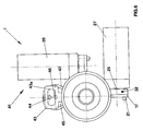
- Fig. 4 is a top view of the delivery device of Fig. 2;
- Fig. 5 is a partial sectional view of the delivery device shown in Fig. 4 taken along the section line V-V;
- Fig. 6 is a left side view of the delivery device of Fig. 4;
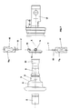
- Fig. 7 is an exploded view of a part of the delivery device of the invention; and
- Fig. 8 is an isometric view of part of the delivery device of the invention.
- The delivery device of the invention is shown in the isometric views of Figs. 1 to 3, where it is generally indicated with
reference numeral 1, and also in Figs. 4 and 5 where it is shown in a partial sectional view. - Moreover the device can be seen also in the general view of Fig. 6 and in the exploded view of Fig. 7 showing only some of its components.
- The
delivery device 1 is particularly adapted to be used in hydro-massage baths and comprises anejector 2 hydraulically connected to an outer duct C1 supplying a liquid to be delivered, which is mechanically connected through articulation means generally indicated with numeral 3 to driving units generally indicated withnumeral 4 adapted to put it in motion. - According to the invention the articulation means 3 comprise an
annular surface 5 made of yielding and elastic material, arranged between a firstannular collar 6 defining theoutlet 7 of the device and a secondannular collar 8 mechanically connected internally to theejector 2 and externally to saiddriving units 4. - More particularly one can see that the
annular surface 5, thefirst collar 6 and thesecond collar 8 belong to a singletubular element 9 which is fully made of yielding and elastic material, preferably but not necessarily an elastomer such as rubber or its mixes. - In the
tubular element 9 afirst inlet way 10 for connection to an outer duct C1 supplying the liquid to be delivered, preferably water, and a second inlet way 11 for connection to an outer duct C2 supplying a gaseous fluid, are defined. - It is to be pointed out that said gaseous fluid is preferably but not necessarily air, which could be replaced or integrated with medical gases of various type.
- Water entering through the
first inlet way 10 is mixed with the gaseous fluid entering through the second inlet way 11 and goes out through theejector 2 conveying it to the body of the person immersed in the bath. - It is the combination of the effect of pressurised water together with the gaseous fluid dissolved in it that carries out the hydro-massage by Venturi effect.
- The
tubular element 9 is removably received in aholding structure 12 constituting the body of thedevice 1 and used to fix the delivery device to the bath. - The
holding structure 12 is also used to support thedriving units 4 for the articulation of theejector 2, which are externally connected to the secondannular collar 8 through anannular ring 13 that can be seen in greater detail in Figs. 7 and 8. - More particularly one can see that the
annular ring 13 is provided withring nuts driving units 4. - Each
driving unit 4 comprises acam screw corresponding ring nut shaped outline pin disc shaft electrical motor - When the
motors pin shaped outline corresponding cam displacement - As each
cam annular ring 13, each cam transmits its displacement to the secondannular collar 9 to which is connected and therefore to theejector 2 that is nip inserted in theannular collar 9. - More particularly, looking at Fig. 8 it is to be noted that the
displacement 28 ofcam 16 gives to the annular ring 13 a rotation around the axis Y laying on plane β and passing by thering nut 15 of connection ofcam 17 and in the same way thedisplacement 29 ofcam 17 gives to the annular ring 13 a rotation around axis Z laying on plane α and passing by thering nut 14 of connection ofcam 16. - Yield and elasticity of the material of the
annular surface 5 connecting the firstannular collar 6 to the secondannular collar 8, thus allowsejector 2 to oscillate both on plane α and plane β with a traverse motion occurring on both planes relative to a theoretical rotation centre O which is placed substantially at the centre ofejector 2, at the point of intersection of the axis X, Y and Z as shown in Fig. 8. - More particularly in this way an oscillatory motion around the point O is obtained for
ejector 2, on the plane of the drawing of Fig. 5 according to opposite directions indicated byarrow 28 and on the plane of the drawing of Fig. 4 according to the opposite directions ofarrow 29. - Both
motors ejector 2 so as to generate for said ejector 2 a curved space motion around the rotation centre O allowing to orient the spout in any direction desired by the user. - Use of the electronic control board allows a fine regulation of the oscillations of
ejector 2 and the presence on thedisc motor magnetic element ejector 2. - Therefore through the control board it is possible to carry out the following steps: traverse
ejector 2 on plane α; traverseejector 2 on plane β; combine the two traverse motions so as to obtain a space rotary motion of theejector 2; change the spraying position of the ejector setting it along different directions at choice of the user. - The delivery device comprises also a
pusher 40 that can be seen particularly in Fig. 4, acting externally on thetubular element 9 at azone 9a of said element, comprised between thefirst inlet way 10 supplying water and the second inlet way 11 supplying the gaseous fluid. - The
pusher 40 is associated to a displacement unit generally indicated with 41, adapted to move it in a rectilinear direction along the lines opposite to each other indicated byarrow 42. - Like the driving units for the
ejector 2, thedisplacement unit 41 comprises acam 43 on theinner profile 43a of which apin 44 is slidingly contacted, belonging to adisc 45 fixed and caused to rotate by theshaft 46 of anelectric motor 47. - In such a way the
cam 43 converts the rotary motion ofshaft 46 ofmotor 47 in a vertical motion ofpusher 40 causing the formation of thetubular element 9 at thecontact zone 9a that can be deformed according to theconfiguration 9b when it is desired to intersect totally the flow through theejector 2. -
Magnetic elements 48 are provided also in thedisc 45, co-operating with fixed sensors to detect and define the position ofpusher 40 and vary the flow rate of the ejector. - Driving properly rotation of the
motor 47 through the mentioned electronic control board, it is possible to vary the position ofpusher 40 so as to modify the shutting degree of thetubular element 9 and therefore water delivery throughejector 2. - From the foregoing it is clear that the invention attains all the intended objects.
- Firstly, connection of
ejector 2 to thedriving units 4 occurs without using mechanical articulation means consisting of two or more mechanical elements pivotally connected to each other because the single yielding element consists of theannular surface 5 made of elastomer. - This makes easier construction and more reliable operation of the ejector.
- Moreover, gaps or undercuts are eliminated and therefore, as shown in Fig. 5, the contact of water from the supply duct C1 to the
ejector 2 continues without meeting discontinuity zone where it is possible collection of polluting material. - Therefore, a delivery device is advantageously obtained warranting a greater hygienic condition, more reliable operation and less expensive in the manufacturing stage.
- In the constructional stage many modifications other than the solutions described and shown in the drawings could be made to the delivery device of the invention.
- It is however to be understood that when said
modifications fall within the scope of the appended claims, they should be all considered covered by the present invention.
Claims (18)
- A delivery device (1) particularly adapted to be used in hydro-massage baths, comprising at least an ejector (2) hydraulically connected to at least an outer duct (C1) supplying a liquid to be delivered and mechanically connected by interposition of articulation means (3) to driving units (4) adapted to put it in motion, characterised in that said articulation means (3) comprise at least an annular surface (5) made of yielding and elastic material arranged between a first annular collar (6) defining the outlet (7) of said device (1) and a second annular collar (8) mechanically connected internally to said ejector (2) and externally to said driving units (4).
- The delivery device (1) according to the claim 1 characterised in that said annular surface (5), said first collar (6) and said second collar (8) belong to a tubular element (9) fully made of yielding and elastic material, provided with a first inlet way (10) for connection of said external duct (C1) supplying said liquid to be delivered and a second inlet way (11) for connection of a second external duct (C2) supplying a gaseous fluid.
- The delivery device (1) according to claim 2 characterised in that said tubular element (9) is removably received in a holding structure (12) constituting the body of the device (1) and supporting said driving units (4) of said ejector.
- The delivery device (1) according to claim 2 characterised in that said second inlet way (11) is made at an intermediate position of said tubular element (9) and downstream said first inlet way (10).
- The delivery device (1) according to claim 1 or 2 characterised in that said yielding and elastic material is an elastomer.
- The delivery device (1) according to claim 1 characterised in that said ejector (2) is internally nip coupled to said second annular collar (8).
- The delivery device (1) according to claim 1 characterised in that an annular ring (13) is provided externally and coaxially to said second annular collar (8), said ring being provided with ring nuts (14, 15) adapted to receive the connection of said driving means (4).
- The delivery device (1) according to claim 7 characterised in that said ring nuts (14, 15) of said annular ring (13) are two and are arranged orthogonally to each other, each ring nut being adapted to receive a screw (18, 19) belonging to a corresponding driving unit (4).
- The delivery device (1) according to claim 8 characterised in that said driving units (4) each comprise at least a cam (16, 17) provided with said screw (18, 19) connecting to the corresponding ring nut (14, 15) of said annular ring (13) and a shaped outline (16a) slidingly co-operating with a corresponding pin (20, 21) arranged eccentrically in a disc (22, 23) coupled to the shaft (24, 25) of an electric motor (26, 27)
- The delivery device (1) according to claim 9 characterised in that the shaped outline (16a, 17a) of each cam (16, 17) co-operates with the corresponding eccentric pin (20, 21) of said disc (22, 23) of said motor (26, 27) and converts the rotary motion of said motor into an oscillating motion of said ejector (2) corresponding to a traverse motion (28, 29) of said ejector on the plane α, β containing said cam (16, 17) and around a rotation axis (Y, Z) belonging to the longitudinal axis of said ring nut (14, 15) fixing the other cam (17, 16) to the same annular ring (13).
- The delivery device (1) according to claim 10 characterised in that said ejector (2) rotates around a point (O) laying at the intersection between the axis (Y, Z) defined by each screw (18, 19) of each cam (16, 17) and the corresponding ring nut (14, 15) of said annular ring (13).
- The delivery device (1) according to claim 2 characterised by comprising at least a pusher (40) acting externally to said tubular element (9) and adapted to deform it to obtain interception or regulation of the flow of said liquid to be delivered.
- The delivery device (1) according to claim 12 characterised in that said pusher (40) is in contact with said tubular element (9) at a zone (9a) comprised between said first inlet way (10) and said second inlet way (11).
- The delivery device (1) according to claim 12 or 13 characterised in that said pusher (40) is associated to a displacement unit (41) adapted to define a generally rectilinear displacement direction (42) for said pusher (40).
- The delivery device (1) according to claim (14) characterised in that said displacement unit (41) comprises a cam (43) connected to said pusher (40) provided with a shaped outline (43a) slidingly co-operating with a corresponding pin (44) eccentrically arranged in a disc (45) coupled to the shaft (46) of an electric motor (47).
- The delivery device (1) according to claim 1 or 15 characterised in that said driving units (4) and said displacement unit (41) are electrically connected to an electronic control board.
- The delivery device (1) according to any of claims 9 or 15 characterised in that said driving units (4) and said displacement unit (41) are provided with means detecting the angular position of the shaft of each electric motor (26, 27, 47).
- The delivery device (1) according to claim 17 characterised in that said position detecting means comprise one or more magnetic bodies (31, 32, 48) inserted in the disc (22, 23, 45) associated to the shaft of each motor (26, 27, 47), co-operating with corresponding fixed reference elements.
Applications Claiming Priority (2)
| Application Number | Priority Date | Filing Date | Title |
|---|---|---|---|
| IT2001VI000067A ITVI20010067A1 (en) | 2001-03-20 | 2001-03-20 | ADJUSTABLE POSITION DISPENSER |
| ITVI010067 | 2001-03-20 |
Publications (2)
| Publication Number | Publication Date |
|---|---|
| EP1243244A1 true EP1243244A1 (en) | 2002-09-25 |
| EP1243244B1 EP1243244B1 (en) | 2004-06-09 |
Family
ID=11461571
Family Applications (1)
| Application Number | Title | Priority Date | Filing Date |
|---|---|---|---|
| EP02006157A Expired - Lifetime EP1243244B1 (en) | 2001-03-20 | 2002-03-19 | Delivery device with adjustable jet orientation |
Country Status (5)
| Country | Link |
|---|---|
| EP (1) | EP1243244B1 (en) |
| AT (1) | ATE268582T1 (en) |
| DE (1) | DE60200594T2 (en) |
| ES (1) | ES2223019T3 (en) |
| IT (1) | ITVI20010067A1 (en) |
Cited By (1)
| Publication number | Priority date | Publication date | Assignee | Title |
|---|---|---|---|---|
| NL1036408C2 (en) * | 2009-01-12 | 2010-07-13 | Villeroy & Boch Wellness B V | Hydromassage device, system comprising a plurality of such devices and wall comprising such a system. |
Citations (2)
| Publication number | Priority date | Publication date | Assignee | Title |
|---|---|---|---|---|
| US5003646A (en) * | 1987-04-14 | 1991-04-02 | Hydro Air Industries, Inc. | Hydrotherapy apparatus |
| WO2000037018A2 (en) * | 1997-09-17 | 2000-06-29 | Hydro Air Industries, Inc. | Hydrotherapy jet with articulating joints |
-
2001
- 2001-03-20 IT IT2001VI000067A patent/ITVI20010067A1/en unknown
-
2002
- 2002-03-19 EP EP02006157A patent/EP1243244B1/en not_active Expired - Lifetime
- 2002-03-19 DE DE60200594T patent/DE60200594T2/en not_active Expired - Lifetime
- 2002-03-19 AT AT02006157T patent/ATE268582T1/en not_active IP Right Cessation
- 2002-03-19 ES ES02006157T patent/ES2223019T3/en not_active Expired - Lifetime
Patent Citations (2)
| Publication number | Priority date | Publication date | Assignee | Title |
|---|---|---|---|---|
| US5003646A (en) * | 1987-04-14 | 1991-04-02 | Hydro Air Industries, Inc. | Hydrotherapy apparatus |
| WO2000037018A2 (en) * | 1997-09-17 | 2000-06-29 | Hydro Air Industries, Inc. | Hydrotherapy jet with articulating joints |
Cited By (2)
| Publication number | Priority date | Publication date | Assignee | Title |
|---|---|---|---|---|
| NL1036408C2 (en) * | 2009-01-12 | 2010-07-13 | Villeroy & Boch Wellness B V | Hydromassage device, system comprising a plurality of such devices and wall comprising such a system. |
| WO2010080026A1 (en) * | 2009-01-12 | 2010-07-15 | Ucosan Bv | Hydromassage device, system comprising a plurality of such devices and wall comprising such a system |
Also Published As
| Publication number | Publication date |
|---|---|
| EP1243244B1 (en) | 2004-06-09 |
| DE60200594T2 (en) | 2005-06-09 |
| ATE268582T1 (en) | 2004-06-15 |
| DE60200594D1 (en) | 2004-07-15 |
| ITVI20010067A1 (en) | 2002-09-20 |
| ES2223019T3 (en) | 2005-02-16 |
Similar Documents
| Publication | Publication Date | Title |
|---|---|---|
| EP0723814B1 (en) | Oscillating shower apparatus | |
| EP0567208A2 (en) | High pressure screen shower | |
| US7806840B2 (en) | Massage device for rubbing, beating and kneading | |
| CN102470385B (en) | Device for dispensing fluid jets without a rotating joint | |
| RU2005106286A (en) | SURFACE TREATMENT DEVICE | |
| US5848444A (en) | Hydrotherapy jet with articulating joints | |
| EP3597283B1 (en) | Filter arrangement | |
| EP1243244B1 (en) | Delivery device with adjustable jet orientation | |
| AU586746B2 (en) | Hydrotherapy apparatus with random discharge pattern across a planar area | |
| US5984883A (en) | Neck massager for use in spas | |
| US4826079A (en) | Moving means for fountain nozzle | |
| US4782551A (en) | Apparatus for cleaning surfaces | |
| NL1036408C2 (en) | Hydromassage device, system comprising a plurality of such devices and wall comprising such a system. | |
| CA1113527A (en) | Shower fittings | |
| KR200196189Y1 (en) | Driving device of nozzle for fountain | |
| KR101894550B1 (en) | Cleaning Apparatus For Narrowness Space | |
| CA2691113A1 (en) | Surface abrader and apparatus for testing surface abrasion | |
| JP7523797B2 (en) | Screen cleaning equipment and solid-liquid separation equipment | |
| KR0135194Y1 (en) | Consecutive cleaning device for electronic parts | |
| CN119184748B (en) | Ultrasonic scanning system for upper digestive tract obstruction | |
| SE0000262L (en) | Apparatus for washing objects such as turbine compressors | |
| RU2531134C1 (en) | Method for performing dynamic hydromassage procedures | |
| WO2000038560A1 (en) | Hydrotherapy jet with articulating joints | |
| SU1270411A1 (en) | Jet pump | |
| WO2000037018A2 (en) | Hydrotherapy jet with articulating joints |
Legal Events
| Date | Code | Title | Description |
|---|---|---|---|
| PUAI | Public reference made under article 153(3) epc to a published international application that has entered the european phase |
Free format text: ORIGINAL CODE: 0009012 |
|
| AK | Designated contracting states |
Kind code of ref document: A1 Designated state(s): AT BE CH CY DE DK ES FI FR GB GR IE IT LI LU MC NL PT SE TR |
|
| AX | Request for extension of the european patent |
Free format text: AL;LT;LV;MK;RO;SI |
|
| 17P | Request for examination filed |
Effective date: 20030324 |
|
| AKX | Designation fees paid |
Designated state(s): AT BE CH CY DE DK ES FI FR GB GR IE IT LI LU MC NL PT SE TR |
|
| GRAH | Despatch of communication of intention to grant a patent |
Free format text: ORIGINAL CODE: EPIDOS IGRA |
|
| GRAS | Grant fee paid |
Free format text: ORIGINAL CODE: EPIDOSNIGR3 |
|
| GRAA | (expected) grant |
Free format text: ORIGINAL CODE: 0009210 |
|
| AK | Designated contracting states |
Kind code of ref document: B1 Designated state(s): AT BE CH CY DE DK ES FI FR GB GR IE IT LI LU MC NL PT SE TR |
|
| PG25 | Lapsed in a contracting state [announced via postgrant information from national office to epo] |
Ref country code: FI Free format text: LAPSE BECAUSE OF FAILURE TO SUBMIT A TRANSLATION OF THE DESCRIPTION OR TO PAY THE FEE WITHIN THE PRESCRIBED TIME-LIMIT Effective date: 20040609 Ref country code: AT Free format text: LAPSE BECAUSE OF FAILURE TO SUBMIT A TRANSLATION OF THE DESCRIPTION OR TO PAY THE FEE WITHIN THE PRESCRIBED TIME-LIMIT Effective date: 20040609 Ref country code: LI Free format text: LAPSE BECAUSE OF FAILURE TO SUBMIT A TRANSLATION OF THE DESCRIPTION OR TO PAY THE FEE WITHIN THE PRESCRIBED TIME-LIMIT Effective date: 20040609 Ref country code: TR Free format text: LAPSE BECAUSE OF FAILURE TO SUBMIT A TRANSLATION OF THE DESCRIPTION OR TO PAY THE FEE WITHIN THE PRESCRIBED TIME-LIMIT Effective date: 20040609 Ref country code: BE Free format text: LAPSE BECAUSE OF FAILURE TO SUBMIT A TRANSLATION OF THE DESCRIPTION OR TO PAY THE FEE WITHIN THE PRESCRIBED TIME-LIMIT Effective date: 20040609 Ref country code: NL Free format text: LAPSE BECAUSE OF FAILURE TO SUBMIT A TRANSLATION OF THE DESCRIPTION OR TO PAY THE FEE WITHIN THE PRESCRIBED TIME-LIMIT Effective date: 20040609 Ref country code: CH Free format text: LAPSE BECAUSE OF FAILURE TO SUBMIT A TRANSLATION OF THE DESCRIPTION OR TO PAY THE FEE WITHIN THE PRESCRIBED TIME-LIMIT Effective date: 20040609 |
|
| REG | Reference to a national code |
Ref country code: GB Ref legal event code: FG4D |
|
| REG | Reference to a national code |
Ref country code: CH Ref legal event code: EP |
|
| REF | Corresponds to: |
Ref document number: 60200594 Country of ref document: DE Date of ref document: 20040715 Kind code of ref document: P |
|
| REG | Reference to a national code |
Ref country code: IE Ref legal event code: FG4D |
|
| PG25 | Lapsed in a contracting state [announced via postgrant information from national office to epo] |
Ref country code: SE Free format text: LAPSE BECAUSE OF FAILURE TO SUBMIT A TRANSLATION OF THE DESCRIPTION OR TO PAY THE FEE WITHIN THE PRESCRIBED TIME-LIMIT Effective date: 20040909 Ref country code: GR Free format text: LAPSE BECAUSE OF FAILURE TO SUBMIT A TRANSLATION OF THE DESCRIPTION OR TO PAY THE FEE WITHIN THE PRESCRIBED TIME-LIMIT Effective date: 20040909 Ref country code: DK Free format text: LAPSE BECAUSE OF FAILURE TO SUBMIT A TRANSLATION OF THE DESCRIPTION OR TO PAY THE FEE WITHIN THE PRESCRIBED TIME-LIMIT Effective date: 20040909 |
|
| NLV1 | Nl: lapsed or annulled due to failure to fulfill the requirements of art. 29p and 29m of the patents act | ||
| REG | Reference to a national code |
Ref country code: CH Ref legal event code: PL |
|
| REG | Reference to a national code |
Ref country code: ES Ref legal event code: FG2A Ref document number: 2223019 Country of ref document: ES Kind code of ref document: T3 |
|
| ET | Fr: translation filed | ||
| PG25 | Lapsed in a contracting state [announced via postgrant information from national office to epo] |
Ref country code: CY Free format text: LAPSE BECAUSE OF FAILURE TO SUBMIT A TRANSLATION OF THE DESCRIPTION OR TO PAY THE FEE WITHIN THE PRESCRIBED TIME-LIMIT Effective date: 20050319 Ref country code: LU Free format text: LAPSE BECAUSE OF NON-PAYMENT OF DUE FEES Effective date: 20050319 |
|
| PG25 | Lapsed in a contracting state [announced via postgrant information from national office to epo] |
Ref country code: IE Free format text: LAPSE BECAUSE OF NON-PAYMENT OF DUE FEES Effective date: 20050321 |
|
| PLBE | No opposition filed within time limit |
Free format text: ORIGINAL CODE: 0009261 |
|
| STAA | Information on the status of an ep patent application or granted ep patent |
Free format text: STATUS: NO OPPOSITION FILED WITHIN TIME LIMIT |
|
| 26N | No opposition filed |
Effective date: 20050310 |
|
| REG | Reference to a national code |
Ref country code: IE Ref legal event code: MM4A |
|
| PG25 | Lapsed in a contracting state [announced via postgrant information from national office to epo] |
Ref country code: PT Free format text: LAPSE BECAUSE OF NON-PAYMENT OF DUE FEES Effective date: 20041109 |
|
| PG25 | Lapsed in a contracting state [announced via postgrant information from national office to epo] |
Ref country code: IT Free format text: LAPSE BECAUSE OF NON-PAYMENT OF DUE FEES Effective date: 20080319 |
|
| PGRI | Patent reinstated in contracting state [announced from national office to epo] |
Ref country code: IT Effective date: 20110616 |
|
| PGFP | Annual fee paid to national office [announced via postgrant information from national office to epo] |
Ref country code: MC Payment date: 20110812 Year of fee payment: 10 |
|
| PGFP | Annual fee paid to national office [announced via postgrant information from national office to epo] |
Ref country code: GB Payment date: 20110819 Year of fee payment: 10 Ref country code: ES Payment date: 20110825 Year of fee payment: 10 Ref country code: FR Payment date: 20110818 Year of fee payment: 10 Ref country code: DE Payment date: 20110810 Year of fee payment: 10 |
|
| PGFP | Annual fee paid to national office [announced via postgrant information from national office to epo] |
Ref country code: IT Payment date: 20110927 Year of fee payment: 10 |
|
| PG25 | Lapsed in a contracting state [announced via postgrant information from national office to epo] |
Ref country code: MC Free format text: LAPSE BECAUSE OF NON-PAYMENT OF DUE FEES Effective date: 20120331 |
|
| GBPC | Gb: european patent ceased through non-payment of renewal fee |
Effective date: 20120319 |
|
| REG | Reference to a national code |
Ref country code: FR Ref legal event code: ST Effective date: 20121130 |
|
| PG25 | Lapsed in a contracting state [announced via postgrant information from national office to epo] |
Ref country code: GB Free format text: LAPSE BECAUSE OF NON-PAYMENT OF DUE FEES Effective date: 20120319 Ref country code: FR Free format text: LAPSE BECAUSE OF NON-PAYMENT OF DUE FEES Effective date: 20120402 |
|
| REG | Reference to a national code |
Ref country code: DE Ref legal event code: R119 Ref document number: 60200594 Country of ref document: DE Effective date: 20121002 |
|
| PG25 | Lapsed in a contracting state [announced via postgrant information from national office to epo] |
Ref country code: IT Free format text: LAPSE BECAUSE OF NON-PAYMENT OF DUE FEES Effective date: 20120319 |
|
| REG | Reference to a national code |
Ref country code: ES Ref legal event code: FD2A Effective date: 20130711 |
|
| PG25 | Lapsed in a contracting state [announced via postgrant information from national office to epo] |
Ref country code: ES Free format text: LAPSE BECAUSE OF NON-PAYMENT OF DUE FEES Effective date: 20120320 |
|
| PG25 | Lapsed in a contracting state [announced via postgrant information from national office to epo] |
Ref country code: DE Free format text: LAPSE BECAUSE OF NON-PAYMENT OF DUE FEES Effective date: 20121002 |