EP1242812B1 - Interferometric microwave sensor - Google Patents
Interferometric microwave sensor Download PDFInfo
- Publication number
- EP1242812B1 EP1242812B1 EP00980562A EP00980562A EP1242812B1 EP 1242812 B1 EP1242812 B1 EP 1242812B1 EP 00980562 A EP00980562 A EP 00980562A EP 00980562 A EP00980562 A EP 00980562A EP 1242812 B1 EP1242812 B1 EP 1242812B1
- Authority
- EP
- European Patent Office
- Prior art keywords
- transmission line
- sensor
- substance
- probe
- electromagnetic energy
- Prior art date
- Legal status (The legal status is an assumption and is not a legal conclusion. Google has not performed a legal analysis and makes no representation as to the accuracy of the status listed.)
- Expired - Lifetime
Links
- 239000000523 sample Substances 0.000 claims description 59
- 230000005540 biological transmission Effects 0.000 claims description 47
- 238000005259 measurement Methods 0.000 claims description 39
- 239000004020 conductor Substances 0.000 claims description 27
- 238000000034 method Methods 0.000 claims description 23
- 239000000126 substance Substances 0.000 claims description 19
- 239000003989 dielectric material Substances 0.000 claims description 15
- 230000005284 excitation Effects 0.000 claims description 6
- 235000020993 ground meat Nutrition 0.000 claims description 5
- 235000020991 processed meat Nutrition 0.000 claims description 5
- 230000001747 exhibiting effect Effects 0.000 claims 2
- 239000000203 mixture Substances 0.000 description 33
- 239000000463 material Substances 0.000 description 19
- 239000007789 gas Substances 0.000 description 15
- 230000008569 process Effects 0.000 description 14
- 230000008901 benefit Effects 0.000 description 10
- 230000010363 phase shift Effects 0.000 description 9
- 230000008859 change Effects 0.000 description 8
- XLYOFNOQVPJJNP-UHFFFAOYSA-N water Substances O XLYOFNOQVPJJNP-UHFFFAOYSA-N 0.000 description 8
- 239000007788 liquid Substances 0.000 description 7
- 238000012544 monitoring process Methods 0.000 description 7
- 230000035945 sensitivity Effects 0.000 description 7
- 238000012360 testing method Methods 0.000 description 7
- 239000000470 constituent Substances 0.000 description 4
- 238000013461 design Methods 0.000 description 4
- 230000000694 effects Effects 0.000 description 4
- 238000002156 mixing Methods 0.000 description 4
- OKKJLVBELUTLKV-UHFFFAOYSA-N Methanol Chemical compound OC OKKJLVBELUTLKV-UHFFFAOYSA-N 0.000 description 3
- 238000010521 absorption reaction Methods 0.000 description 3
- 230000008878 coupling Effects 0.000 description 3
- 238000010168 coupling process Methods 0.000 description 3
- 238000005859 coupling reaction Methods 0.000 description 3
- 230000001419 dependent effect Effects 0.000 description 3
- 238000010586 diagram Methods 0.000 description 3
- 239000012530 fluid Substances 0.000 description 3
- 239000002184 metal Substances 0.000 description 3
- 229910052751 metal Inorganic materials 0.000 description 3
- 238000012986 modification Methods 0.000 description 3
- 230000004048 modification Effects 0.000 description 3
- 230000004044 response Effects 0.000 description 3
- 239000007787 solid Substances 0.000 description 3
- 239000000758 substrate Substances 0.000 description 3
- RTZKZFJDLAIYFH-UHFFFAOYSA-N Diethyl ether Chemical compound CCOCC RTZKZFJDLAIYFH-UHFFFAOYSA-N 0.000 description 2
- 239000011248 coating agent Substances 0.000 description 2
- 238000000576 coating method Methods 0.000 description 2
- 238000010276 construction Methods 0.000 description 2
- 235000013305 food Nutrition 0.000 description 2
- 230000035699 permeability Effects 0.000 description 2
- 238000007789 sealing Methods 0.000 description 2
- 239000011343 solid material Substances 0.000 description 2
- RYGMFSIKBFXOCR-UHFFFAOYSA-N Copper Chemical group [Cu] RYGMFSIKBFXOCR-UHFFFAOYSA-N 0.000 description 1
- 240000002129 Malva sylvestris Species 0.000 description 1
- 235000006770 Malva sylvestris Nutrition 0.000 description 1
- 229920000426 Microplastic Polymers 0.000 description 1
- 238000004458 analytical method Methods 0.000 description 1
- 230000000712 assembly Effects 0.000 description 1
- 238000000429 assembly Methods 0.000 description 1
- 230000009286 beneficial effect Effects 0.000 description 1
- 238000004364 calculation method Methods 0.000 description 1
- 238000012512 characterization method Methods 0.000 description 1
- 235000013351 cheese Nutrition 0.000 description 1
- 238000006243 chemical reaction Methods 0.000 description 1
- 239000003245 coal Substances 0.000 description 1
- 229910052802 copper Inorganic materials 0.000 description 1
- 239000010949 copper Substances 0.000 description 1
- 238000005260 corrosion Methods 0.000 description 1
- 230000007797 corrosion Effects 0.000 description 1
- 238000007405 data analysis Methods 0.000 description 1
- 230000003247 decreasing effect Effects 0.000 description 1
- 230000001066 destructive effect Effects 0.000 description 1
- 238000010981 drying operation Methods 0.000 description 1
- 230000005672 electromagnetic field Effects 0.000 description 1
- 238000005516 engineering process Methods 0.000 description 1
- 239000010881 fly ash Substances 0.000 description 1
- 239000008240 homogeneous mixture Substances 0.000 description 1
- 229930195733 hydrocarbon Natural products 0.000 description 1
- 150000002430 hydrocarbons Chemical class 0.000 description 1
- 238000012625 in-situ measurement Methods 0.000 description 1
- 230000001939 inductive effect Effects 0.000 description 1
- 238000003780 insertion Methods 0.000 description 1
- 230000037431 insertion Effects 0.000 description 1
- 230000002452 interceptive effect Effects 0.000 description 1
- 238000011835 investigation Methods 0.000 description 1
- 238000004519 manufacturing process Methods 0.000 description 1
- 235000013372 meat Nutrition 0.000 description 1
- 235000013336 milk Nutrition 0.000 description 1
- 239000008267 milk Substances 0.000 description 1
- 210000004080 milk Anatomy 0.000 description 1
- TVMXDCGIABBOFY-UHFFFAOYSA-N octane Chemical compound CCCCCCCC TVMXDCGIABBOFY-UHFFFAOYSA-N 0.000 description 1
- 230000035515 penetration Effects 0.000 description 1
- 229920003023 plastic Polymers 0.000 description 1
- 239000000843 powder Substances 0.000 description 1
- 238000005070 sampling Methods 0.000 description 1
- 238000004611 spectroscopical analysis Methods 0.000 description 1
- 238000001228 spectrum Methods 0.000 description 1
- 230000003068 static effect Effects 0.000 description 1
Images



Classifications
-
- G—PHYSICS
- G01—MEASURING; TESTING
- G01N—INVESTIGATING OR ANALYSING MATERIALS BY DETERMINING THEIR CHEMICAL OR PHYSICAL PROPERTIES
- G01N22/00—Investigating or analysing materials by the use of microwaves or radio waves, i.e. electromagnetic waves with a wavelength of one millimetre or more
Definitions
- the present invention relates generally to the in situ measurement of the bulk electrical properties of various substances, often fluid mixtures, and the interpretation of such direct electrical measurements to produce an indirect or inferred measurement of the composition of a given substance or mixture based upon the change in electrical properties that occurs as the relative percentages of the components in the mixture vary.
- the invention also has application to solid substances having a surface that can be interrogated by placing the surface of a suitably configured probe against or in close proximity to the substance surface.
- the electrical permittivity of a nominally homogeneous mixture depends upon the volumetric ratio of the constituent materials and upon the permittivity of the individual components.
- Microwave instruments exploit this fact to analyze the properties of substances or the composition of mixtures by measuring and analyzing various attributes of a microwave signal or set of signals that depend directly upon the permittivity of the substance or mixture.
- instruments in a variety of configurations are available which measure the attenuation or phase shift of signals that are transmitted through an unknown mixture.
- the material sample may be placed between transmitting and receiving antennas as described in Swanson, US Patent 4,812,739.
- the sample may be loaded into a coaxial or waveguide structure that supports the propagation of the wave or waves according to the inventions contained in Jean et al., US Patent 5,455,516; Scott et al. US Patent 4,862,060; or De et al. US Patent 4,902,961.
- prior-art reflection sensors are available which rely on measuring the amplitude and phase of the reflection coefficient at the interface between a probe element and the mixture surface. For example, see “A Novel Numerical Technique for Dielectric Measurement of Generally Lossy Dielectrics” by Ganchev, Bakhtiari, and Zorghi, IEEE Transactions on Instrumentation and Measurement, Vol. 41, No 3, June 1992.
- the most sensitive reflection sensors cannot reliably measure the extremely small electrical differences that are associated with many important applications, such as the measurement of steam quality.
- Shearer et al. teach a microwave absorption technique for analyzing gases in US Patent 5,507,173.
- This analyzer employs parallel microwave beams, but the separate beams pass through independent measurement cells and an elaborate arrangement of attenuators and signal splitters is needed to determine the difference in microwave absorption between a one cell containing a reference gas and another containing the gas under test.
- the analyzer operates at a single carefully controlled frequency selected to correspond to an absorption line of the gas being analyzed.
- Carullo, Ferrero and Parvis in "A Microwave Interferometer System for Humidity Measurement” describe an interferometer technique for the measurement of humidity. This interferometer falls short in two important respects. First, the dynamic range of the interferometer method described by Carullo is severely limited. Secondly, Carullo describes a phase measurement being made on interfering signals that are at a constant frequency. As a consequence, the interferometer is severely limited in sensitivity and accuracy. Also, the Carullo interferometer does not allow for the measurement of the loss factor of the material.
- US-patent 5,073,755 discloses a dielectric test device formed on a substrate which includes a conductive ground plane layer formed over the substrate, a dielectric layer over the ground plane layer and a short and long conductive strip overlying the dielectric layer.
- the long and shorts strips have a common input and output node.
- An input signal of a single frequency is applied to the input node, and measurement of interference pattern at the output node is made as a function of frequency. That allows the calculation of effective dielectric constant as well as propagation velocity.
- US-patent 5,334,941 discloses a sensor for non-destructively measuring the complex dielectric and conductive properties of solids, liquids, or gasses at microwave frequencies.
- multiple microstrip resonators are etched on the surface of a dielectric substrate which is bonded to a copper ground plane.
- the resonators are electromagnetically driven by mutual inductive coupling to a short non-resonant feed slot. As the frequency of the mircrowave source is swept, a sharp dip in the reflected wave occurs at the resonant frequency from which small changes in the dielectric constant and in the conductivity can be deduced.
- WO95/03542 discloses a device for electronic monitoring and characterization using single-ended coupling of a load-pulled oscillator to a system under test. Two different signal paths can be provided in the probe, and these can have a short circuit termination. A ground plane may be complanar to the signal path or on the back side of the probe.
- US-patent 5,363,052 discloses a permittivity spectroscopy apparatus.
- that apparatus uses a microstrip assembly or circuit.
- the microstrip assembly can be formed by placing two microstrip assemblies bottom to bottom so that lower enclosures or a base abut each other.
- the microstrip assembly can have a single base or lower enclosure with two chambers and two upper enclosures.
- microwave-based sensor that has sufficient precision to reliably monitor the composition of mixtures of gases, while having sufficient dynamic range to address applications where the mixtures contain large variations in moisture and the process undergoes large swings in pressure and temperature.
- a microwave sensor that can maintain a sensitive measurement as the probe element is subjected to wear or corrosion in harsh environment of the measurement zone. Additional needs include that the probe be insensitive to stray reflections and other signal artifacts that can render prior art sensor inoperative and that the probe requires very low signal power to operate. The ability to operate at very low power levels is desired to reduce the sensor cost and mitigate operational problems in satisfying FCC rules.
- the present invention achieves technical advantages as a microwave-based sensor having improved sensitivity over prior art microwave-based sensors.
- the sensor is rugged in construction and low in cost to produce.
- One preferred embodiment of the invention is a probe-type sensing element which is insertable into a vessel or pipe and is suitable for monitoring changes in the electrical properties of steam.
- a sensor with improved sensitivity is required for steam quality measurement because of the relatively small change in permittivity of wet steam over a quality range as large as even from 50 to 100%.
- other configurations for the sensor that are suitable for a wide range of applications are also contemplated within the scope of the invention and examples will be given.
- the sensor accomplishes a measurement by varying the frequency of the microwave excitation signal and observing when a minimum ("null") is detected for the vector sum of two output signals.
- the two signals travel unequal electrical distances.
- the vector summation will be a minimum (null) whenever the electrical traveled distances differ by a half wavelength, or an odd integral multiple of a half wavelength. It should be appreciated by those skilled in the art that the same general effect can be obtained by inverting the signal in one of the signal paths, such that the signals will produce a minimum output (null) for those frequencies for which the paths differ in length by a full wavelength or an integral multiple of a full wavelength.
- the electrical distance of travel is dependent upon the dielectric properties of the material under test.
- the frequency required to make the electrical length difference equal to a half wavelength will also change. Determining this null frequency therefore represents a direct measurement of the dielectric constant and hence the relative composition of the mixture.
- a sensor for the measurement of steam quality may employ a probe that has signal paths that differ by 1.5 cm in physical length. In vacuum, this path difference corresponds to a half wavelength at a frequency of approximately 10 GHz. For dry steam according to the conditions specified above, the frequency shifts to a value of 9.937589 GHz. For 50% quality steam, a frequency of 9.618353 GHz is observed, a frequency difference of more than 319 MHz. Microwave circuits are readily available which are stable to within a few parts per million and frequency measurements are easily accomplished to a similar precision.
- the null frequency value depends primarily upon the real part of the permittivity. As the signals from the two paths are combined so as to produce the null by destructive interference, the depth of the null will depend upon the amount of attenuation that the waves have experienced. Observing the depth of the null thus provides one measure of the imaginary part of the permittivity or loss factor. The total amplitude of the reflection for an off-null condition will also be indicative of the loss factor encountered by the signals. The overall length of the signal paths will influence the sensitivity of the loss factor measurement. In the applications it is beneficial to have two signal paths inserted into the process stream so as to take advantage of common mode rejection of the effects of external parameters that are unrelated to the composition measurement.
- One alternative configuration for a microwave sensor according to the teaching of the present invention is to embed the transmission lines in a dielectric material along the walls of the pipe or vessel so as to not have a probe element protruding into the process stream or vessel.
- Such a configuration will have less sensitivity than a probe-type sensing element, but there are many applications that can be addressed with more than enough precision owing to the inherent advantages of the invention.
- Yet another configuration is to embed the transmission lines in a dielectric material and still configure the sensor as a probe element. Such a configuration would be suitable for a portable version of the instrument for applications such as the sampled measurement of the percent of fat in processed or ground meat.
- Yet another configuration consistent with the teaching of the present invention is to transmit the microwave energy through the process material and to have either two transmitting elements or two receiving elements and locate them in a position such that parallel paths differing in length are formed.
- the transmitting and receiving elements are embedded in the walls of a metal pipe or vessel using suitable microwave transparent windows, or for the case of a plastic pipe or vessel, the transmitting and receiving elements are mounted on the outside of the pipe. For this configuration care must be taken to prevent the occurrence of multiple signal paths, which would potentially introduce false signals and readings.
- fluid mixture refers to any type of mixture of gas, liquid, or solid components that generally flow and conform or can be caused to conform to the shape of the mixture's container or to the surface of an inserted probe or sensing element.
- the present invention is configured to measure the electrical properties of the materials in the microwave portion of the electromagnetic spectrum.
- the term "electrical properties" refers to both the electrical permittivity and the magnetic permeability of the substance or material under investigation. Both of these material properties are described mathematically by real and imaginary terms and may be dependent upon the orientation and strength of the applied electromagnetic fields. For most applications of interest in industrial processes, only the linear scalar complex electrical permittivity comes into play. For brevity, the descriptions of the invention will assume electrical permittivity or dielectric constant to be the variable of interest. It will be understood by those skilled in the art that the descriptions could also incorporate the effects of magnetic permeability and the non-linear and tensor nature of both the electrical and magnetic parameters without altering the scope of the present invention.
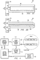
- the simplest structure for a probe element is shown at 10 and is configured to have two electrical paths 12 and 14 that differ in physical length, as is depicted in Figure 1.
- the probe structure 10 of Figure 1 has two image line transmission lines 16 and 18 that share a common ground plane conductor 20. Each transmission line 16 and 18 is terminated in a short circuit at the ground plane 20 so as to reflect the signal back to the source end of the probes shown at 24 and 26.
- the use of a reflecting termination is a convenient way to extract the signal from the probe without the need for an additional penetration into the vessel.
- the probe 10 is inserted into a pipe 36 in which process material is flowing, the probe 10 is oriented so that the large flat surface of the ground plane member shown at 20 is parallel to the direction of flow. In this way, the process flow experiences the least restriction and both transmission lines 16 and 18 are equally exposed to the material under test. It should be appreciated by those skilled in the art that the choice of an image line configuration is only one of many possible options for the probe's transmission lines using this teaching.
- the image line conductors 16 and 18 penetrate the probe's mounting flange 30 and are insulated by a dielectric material 32 that also seals the space around each conductor 16 and 18.
- a dielectric material 32 that also seals the space around each conductor 16 and 18.
- Many dielectric materials are available which can provide a suitable dielectric value as well as a secure seal.
- the diameter of each conductor 16 and 18 and the dielectric seal are selected to provide adequate strength for each component and also to control the characteristic impedance of the line as it passes through the metal flange 30.
- the design equations for controlling the impedance of the line are well known by those skilled in the art.
- the conductors 16 and 18, which exit the probe through the rear side of mounting flange 30, are connected to the probe's electronic circuits 40 (as shown in figure 4) either by cable or by other direct connection.
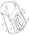
- a preferred embodiment and advantage of the invention is to eliminate the use of coaxial cables and associated connectors by extending the center conductors 49, 50 directly into the enclosure 46 for the microwave circuit, thereby forming a rigid integral unit.
- One such interface is to have the center conductor 20 extend through flange 30 and into a section of rectangular waveguide 46 in a manner similar to standard coax-to-waveguide adapters, as shown in Figure 2.
- the transmission lines 16 and 18 are mounted through respective RF feedthroughs 48, as shown. This particular interface is especially well suited to high pressure applications because the dielectric material 32 of the process seal need not be penetrated by the metal conductors 49 and 50, thereby eliminating the difficult task of sealing around the conductors.
- a waveguide interface is very convenient for sealing purposes, it also makes sense to use a waveguide hybrid-tee 46 to separate the excitation and reflected signals.
- the main body of the hybrid-tee 46 can be machined directly into the surface of the mounting flange 30. Such an arrangement helps to reduce the cost of the overall sensor 10 and provides an extremely robust and compact microwave interface. This arrangement works well for high temperature applications since there are no temperature critical components required as part of the hybrid-tee 46 structure.
- the external waveguide sections of the hybrid-tee 46 can be made to any convenient length, thereby allowing the active electronic components, such as a signal generator and the signal detector 52, to be well removed from the harsh conditions of the mounting flange 30, yet still avoiding the use of coaxial cables and the corresponding troublesome connectors:
- FIG. 1B, Figure 1C and Figure 1D illustrate a modified probe 60 being similar to probe 10 of figure 1A, the transmission lines 16 and 18 are sealed to a mounting flange 62 by a respective dielectric mounting receptacle.
- FIG. 3A Another probe configuration 70 is shown in Figure 3A. Again, the arrangement of the conductors 72 and 74 for the transmission lines is that of an image line structure, having a ground plane conductor 82. In this case, however, the electrical lengths of the two transmission line paths 76 and 78 are caused to differ by coating the primary conductor 74 of one of the image lines with a dielectric material 80. The presence of the dielectric material 80 around the conductor 74 will alter the velocity of propagation for the wave travelling along this path 78, hence, the electrical length of path 78 will differ the electrical length of path 76 from the non-coated probe 72. The remaining features of such a probe configuration 70 do not change from that of probe 10.
- the distinguishing performance feature of this particular arrangement is that the probe 10 will tend to respond to the averaged effect of the dielectric properties along the entire length of the probe transmission lines 72 and 74.
- the probes of Figure 1A and Figure 1B will tend to respond more to the dielectric properties in the differential length section "L" of the longer of the two transmission lines 16.
- FIG. 3B Yet another probe is shown at 90 in Figure 3B, Figure 3C and Figure 3D having RF feedthroughs 92 for each of transmission lines 94 and 96 with a dielectric material 98 being disposed about transmission line 94, and a large common transmission line 100.
- the block diagram shown in Figure 4 shows the basic components necessary for the complete sensor to function.
- the system requires a variable frequency source of microwave energy 110 that can be precisely controlled.
- the output information derived from the sensor is the frequency at which a null condition is observed which is calculated by the sensor's detector circuit 112.
- Both the frequency source 110 and the detector 112 are connected to a hybrid coupler 114.
- the coupler 114 directs the energy from the source 110 to the two transmission paths of the probe elements, and also combines the return signal from the probe and presents it to the detector 112.
- the sensor operation is controlled and monitored by a suitable control and data analysis computer 120 having DSP circuitry or the like.
- the ultimate data from the utilized probe is directed to a display/output interface unit 122 that interfaces with the user and other control equipment.
- the sensor configuration 200 of Figure 5 has several distinctive performance features. First is the appreciated fact that nothing protrudes into the process stream fluid path to restrict the flow of the process material. This non-intrusive arrangement 200 is an important technical advantage for process streams traveling at high velocities or containing a large volume of solid material. A second feature and technical advantage is that the sensor 202 is less sensitive to changes in dielectric properties and can therefore handle a wide span in properties without requiring an excessively wideband frequency source. This configuration 200 can potentially handle more highly conductive mixtures than the other sensor designs.
- Yet another configuration is to embed the transmission lines in a dielectric material and still configure the sensor as a probe element.
- the configuration 250 shown in Figure 6 is that of a completely sealed probe design 260. Because the probe 260 is completely sealed, the probe 260 is less sensitive than the probe 10 shown in Figure 1, but it will, however, still address a wide range of important applications.
- Probe 160 has the benefit of being suitable for a portable version of the sensor. Such a configuration would be suitable for a portable version of the instrument for applications such as the sampled measurement of the percent of fat in processed or ground meat.
- the dielectric constant of the mixture is dependent upon the volume fraction, ⁇ , of the mixture constituents multiplied times the square root of the dielectric constant, ⁇ , of that constituent added to a similar factor for each constituent in the mixture. The sum of these terms is squared to give the resulting dielectric constant of the mixture.
- phase shift that would be experienced by a wave traveling along a transmission line having steam as the surrounding dielectric versus a wave traveling in free space
- the amount of phase shift will depend upon the length of the line and the frequency of the energy.
- the graph in Figure 11 shows the total amount of phase shift difference that can be expected for a line that is 3 inches in length at a frequency of 10.525 GHz.
- the graph clearly reveals to those skilled in the art that a simple phase shift measurement is not sensitive enough to do a good job of measuring steam quality in the 50% to 100% range. Phase shift measurements, at the very best, can be achieved to an accuracy of plus or minus a few degrees.
- the total frequency shift for 50 to 100% quality steam using the sensor designed according to the present invention is shown in Figure 12A and Figure 12B.
- Those skilled in the art will readily recognize and appreciate that a very precise measurement of steam quality is afforded by measuring the "null frequency". Based upon readily available methods for generating microwave frequencies and the readily available methods for measuring such "null" frequencies, as it was shown previously, the steam quality can be measured to a precision of plus or minus 0.0156 %, a very high resolution.
- the present invention derives technical advantages by having application to a wide range of measurement problems.
- the preferred embodiment described, as illustrated for the steam quality sensor is itself useful for numerous applications other than steam quality, particularly those applications for which large changes in substance properties result in relatively small changes in electrical parameters or the dielectric properties are near that of air, including wet gas measurement, gas composition measurement, bag breakout monitoring, dryer completion monitoring, moisture content in pneumatically conveyed materials, measurement of fly ash percentage in stack gases, etc.
- wet gas measurement gas composition measurement
- bag breakout monitoring bag breakout monitoring
- dryer completion monitoring moisture content in pneumatically conveyed materials
- measurement of fly ash percentage in stack gases etc.
- other embodiments are contemplated.
- the operating frequency and the difference in transmission path length may not be selected independently.
- operating frequency refers to the frequency for which a null output condition is produced for a given value of dielectric constant. If the operating frequency is given, then the transmission path length is generally fixed by the electrical properties of the material under test.
- a simple relationship exists between the operating frequency, f , and the relative dielectric constant, ⁇ r , and the difference in path length, ⁇ L, and the number of half wavelengths, n , represented by the ⁇ L value according to the following equation: ⁇ r n ⁇ c 2 ( ⁇ ⁇ L ) f 2 where c is the speed of light in vacuum.
- This relationship is referred by the inventors as Delta-L( ⁇ L) technology. This expression assumes a TEM wave traveling along the transmission lines. For other modes of propagation, such as in a waveguide, the expression requires modification such that the speed of light, c, is replaced with the vacuum velocity of that particular mode.
- the range in dielectric constant values that are to be measured by the sensor determines the required bandwidth of the signal source 110. Some flexibility is possible in constraining the required bandwidth. It is possible to switch in and out various lengths of transmission line to effectively adjust the phase of the signal on one of the transmission paths with respect to the other, so that the frequency required to produce the null is modified by the change in the length of the line. It is contemplated within the scope of the present invention that a lower cost version of the sensor could incorporate switchable sections of line, perhaps varying by factors of two to facilitate a digital representation of the inserted length, so that a relatively narrow bandwidth frequency source 110 could accommodate a large variation in dielectric constant for the process material under test.
Landscapes
- Physics & Mathematics (AREA)
- Electromagnetism (AREA)
- Health & Medical Sciences (AREA)
- Life Sciences & Earth Sciences (AREA)
- Chemical & Material Sciences (AREA)
- Analytical Chemistry (AREA)
- Biochemistry (AREA)
- General Health & Medical Sciences (AREA)
- General Physics & Mathematics (AREA)
- Immunology (AREA)
- Pathology (AREA)
- Measurement Of Resistance Or Impedance (AREA)
- Investigating Or Analyzing Materials By The Use Of Electric Means (AREA)
Description
- Priority is claimed of commonly assigned co-pending U.S. provisional patent application, serial number 60/166,445 filed November 19, 1999 entitled "A Microwave Sensor", the teachings included herein by reference.
- The present invention relates generally to the in situ measurement of the bulk electrical properties of various substances, often fluid mixtures, and the interpretation of such direct electrical measurements to produce an indirect or inferred measurement of the composition of a given substance or mixture based upon the change in electrical properties that occurs as the relative percentages of the components in the mixture vary. In some situations the invention also has application to solid substances having a surface that can be interrogated by placing the surface of a suitably configured probe against or in close proximity to the substance surface.
- The electrical permittivity of a nominally homogeneous mixture depends upon the volumetric ratio of the constituent materials and upon the permittivity of the individual components. Microwave instruments exploit this fact to analyze the properties of substances or the composition of mixtures by measuring and analyzing various attributes of a microwave signal or set of signals that depend directly upon the permittivity of the substance or mixture.. For example, instruments in a variety of configurations are available which measure the attenuation or phase shift of signals that are transmitted through an unknown mixture. The material sample may be placed between transmitting and receiving antennas as described in Swanson, US Patent 4,812,739. Alternatively, the sample may be loaded into a coaxial or waveguide structure that supports the propagation of the wave or waves according to the inventions contained in Jean et al., US Patent 5,455,516; Scott et al. US Patent 4,862,060; or De et al. US Patent 4,902,961.
- Likewise, prior-art reflection sensors are available which rely on measuring the amplitude and phase of the reflection coefficient at the interface between a probe element and the mixture surface. For example, see "A Novel Numerical Technique for Dielectric Measurement of Generally Lossy Dielectrics" by Ganchev, Bakhtiari, and Zorghi, IEEE Transactions on Instrumentation and Measurement, Vol. 41,
No 3, June 1992. However, even the most sensitive reflection sensors cannot reliably measure the extremely small electrical differences that are associated with many important applications, such as the measurement of steam quality. - Shearer et al. teach a microwave absorption technique for analyzing gases in US Patent 5,507,173. This analyzer employs parallel microwave beams, but the separate beams pass through independent measurement cells and an elaborate arrangement of attenuators and signal splitters is needed to determine the difference in microwave absorption between a one cell containing a reference gas and another containing the gas under test. The analyzer operates at a single carefully controlled frequency selected to correspond to an absorption line of the gas being analyzed.
- Carullo, Ferrero and Parvis in "A Microwave Interferometer System for Humidity Measurement" describe an interferometer technique for the measurement of humidity. This interferometer falls short in two important respects. First, the dynamic range of the interferometer method described by Carullo is severely limited. Secondly, Carullo describes a phase measurement being made on interfering signals that are at a constant frequency. As a consequence, the interferometer is severely limited in sensitivity and accuracy. Also, the Carullo interferometer does not allow for the measurement of the loss factor of the material.
- US-patent 5,073,755 discloses a dielectric test device formed on a substrate which includes a conductive ground plane layer formed over the substrate, a dielectric layer over the ground plane layer and a short and long conductive strip overlying the dielectric layer. The long and shorts strips have a common input and output node. An input signal of a single frequency is applied to the input node, and measurement of interference pattern at the output node is made as a function of frequency. That allows the calculation of effective dielectric constant as well as propagation velocity.
- US-patent 5,334,941 discloses a sensor for non-destructively measuring the complex dielectric and conductive properties of solids, liquids, or gasses at microwave frequencies. In one embodiment, multiple microstrip resonators are etched on the surface of a dielectric substrate which is bonded to a copper ground plane. The resonators are electromagnetically driven by mutual inductive coupling to a short non-resonant feed slot. As the frequency of the mircrowave source is swept, a sharp dip in the reflected wave occurs at the resonant frequency from which small changes in the dielectric constant and in the conductivity can be deduced.
- WO95/03542 discloses a device for electronic monitoring and characterization using single-ended coupling of a load-pulled oscillator to a system under test. Two different signal paths can be provided in the probe, and these can have a short circuit termination. A ground plane may be complanar to the signal path or on the back side of the probe.
- US-patent 5,363,052 discloses a permittivity spectroscopy apparatus. In one embodiment, that apparatus uses a microstrip assembly or circuit. The microstrip assembly can be formed by placing two microstrip assemblies bottom to bottom so that lower enclosures or a base abut each other. Alternatively, the microstrip assembly can have a single base or lower enclosure with two chambers and two upper enclosures.
- There is a significant need for a microwave-based sensor that has sufficient precision to reliably monitor the composition of mixtures of gases, while having sufficient dynamic range to address applications where the mixtures contain large variations in moisture and the process undergoes large swings in pressure and temperature.
- In addition, there is a need for a microwave sensor that can maintain a sensitive measurement as the probe element is subjected to wear or corrosion in harsh environment of the measurement zone. Additional needs include that the probe be insensitive to stray reflections and other signal artifacts that can render prior art sensor inoperative and that the probe requires very low signal power to operate. The ability to operate at very low power levels is desired to reduce the sensor cost and mitigate operational problems in satisfying FCC rules.
- As an example of the need for an improved microwave sensor, consider the application of measuring the composition of a gas mixture such as encountered in the measurement of steam quality. Gases have dielectric constants very near that of free space. For example, dry steam at 110 degrees Celsius has a relative dielectric constant of 1.0126 as reported in the Handbook of Chemistry and Physics 63rd Edition, CRC Press, Inc., 1983. Theoretical computations predict that the relative dielectric constant for 50% quality steam will increase to only 1.081. This change in dielectric constant is 6.75% for a 50% change in steam quality. It will be clear in the descriptions that follow that the present invention can easily distinguish such small changes.
- The present invention achieves technical advantages as a microwave-based sensor having improved sensitivity over prior art microwave-based sensors. The sensor is rugged in construction and low in cost to produce.
- One preferred embodiment of the invention is a probe-type sensing element which is insertable into a vessel or pipe and is suitable for monitoring changes in the electrical properties of steam. A sensor with improved sensitivity is required for steam quality measurement because of the relatively small change in permittivity of wet steam over a quality range as large as even from 50 to 100%. As will be evident from the discussions that follow, other configurations for the sensor that are suitable for a wide range of applications are also contemplated within the scope of the invention and examples will be given.
- The sensor accomplishes a measurement by varying the frequency of the microwave excitation signal and observing when a minimum ("null") is detected for the vector sum of two output signals. The two signals travel unequal electrical distances. The vector summation will be a minimum (null) whenever the electrical traveled distances differ by a half wavelength, or an odd integral multiple of a half wavelength. It should be appreciated by those skilled in the art that the same general effect can be obtained by inverting the signal in one of the signal paths, such that the signals will produce a minimum output (null) for those frequencies for which the paths differ in length by a full wavelength or an integral multiple of a full wavelength. The electrical distance of travel is dependent upon the dielectric properties of the material under test. As the electrical permittivity (or dielectric constant, as it is commonly known) of the material mixture responds to changing amounts of its electrically different components, then the frequency required to make the electrical length difference equal to a half wavelength will also change. Determining this null frequency therefore represents a direct measurement of the dielectric constant and hence the relative composition of the mixture.
- Consider some specifics of the design, for example, of a sensor for the measurement of steam quality. Such a sensor may employ a probe that has signal paths that differ by 1.5 cm in physical length. In vacuum, this path difference corresponds to a half wavelength at a frequency of approximately 10 GHz. For dry steam according to the conditions specified above, the frequency shifts to a value of 9.937589 GHz. For 50% quality steam, a frequency of 9.618353 GHz is observed, a frequency difference of more than 319 MHz. Microwave circuits are readily available which are stable to within a few parts per million and frequency measurements are easily accomplished to a similar precision. If we consider a frequency measurement accuracy of only 100 parts per million, then the 50% steam quality range can be measured to a precision of +/- .0156% of steam quality. Certainly, there are other factors, such as temperature and pressure, that will affect the steam quality measurement, but the sensor itself clearly has sufficient precision for the task.
- The null frequency value depends primarily upon the real part of the permittivity. As the signals from the two paths are combined so as to produce the null by destructive interference, the depth of the null will depend upon the amount of attenuation that the waves have experienced. Observing the depth of the null thus provides one measure of the imaginary part of the permittivity or loss factor. The total amplitude of the reflection for an off-null condition will also be indicative of the loss factor encountered by the signals. The overall length of the signal paths will influence the sensitivity of the loss factor measurement. In the applications it is beneficial to have two signal paths inserted into the process stream so as to take advantage of common mode rejection of the effects of external parameters that are unrelated to the composition measurement.
- One alternative configuration for a microwave sensor according to the teaching of the present invention is to embed the transmission lines in a dielectric material along the walls of the pipe or vessel so as to not have a probe element protruding into the process stream or vessel. Such a configuration will have less sensitivity than a probe-type sensing element, but there are many applications that can be addressed with more than enough precision owing to the inherent advantages of the invention.
- Yet another configuration is to embed the transmission lines in a dielectric material and still configure the sensor as a probe element. Such a configuration would be suitable for a portable version of the instrument for applications such as the sampled measurement of the percent of fat in processed or ground meat.
- Yet another configuration consistent with the teaching of the present invention is to transmit the microwave energy through the process material and to have either two transmitting elements or two receiving elements and locate them in a position such that parallel paths differing in length are formed. For this configuration, the transmitting and receiving elements are embedded in the walls of a metal pipe or vessel using suitable microwave transparent windows, or for the case of a plastic pipe or vessel, the transmitting and receiving elements are mounted on the outside of the pipe. For this configuration care must be taken to prevent the occurrence of multiple signal paths, which would potentially introduce false signals and readings.
-
- Figure 1A would depict a probe element according to a first preferred embodiment of the present invention, where the two-way signal paths for the probe shown in Figure 1 differ in physical length;
- Figure 1B would depict a probe similar to that shown in Figure 1A according to another preferred embodiment;
- Figure 1C would depict a side view of the probe shown in Figure 1B;
- Figure 1D would depict a bottom view of the probe of Figure 1B;
- Figure 2 illustrates some of the details of the construction of one embodiment of the process seal/microwave coupling structure suitable for a high-temperature, high-pressure application;
- Figure 3A illustrates a second configuration for a probe element in which the physical lengths of the two two-way signal paths are equal. The electrical length of one path is made longer by coating one conductor of one of the transmission lines with a dielectric material, thereby causing the velocity of propagation to be decreased;
- Figure 3B illustrates a probe similar to that shown in Figure 3A according to another preferred embodiment;
- Figure 3C depicts a side view of the probe of Figure 3B;
- Figure 3D is a bottom view of the probe of Figure 3B;
- Figure 4 is a block diagram of a complete sensor assembly. The electronic circuits identified in the block diagram may be used with multiple probe configuration;
- Figure 5 shows a possible configuration for a probe mounted in the wall of a pipe or vessel;
- Figure 6 illustrates a probe configuration suitable for a portable version of the invention that would lend itself to a batch-sampling instrument, having utility for such applications as processed or ground meats, batch mixed doughs and batters, etc;
- Figure 9 depicts the dielectric constant of steam over the full range of steam quality;
- Figure 10A expands the graph of Figure 9 in the important range of steam quality values form 50 to 100%;
- Figure 10B illustrates the total amount of phase shift difference that can be expected for a line that is 3 inches in length of a frequency of 10.525 GHz;
- Figure 11 is a graph of the response of a prior art phase shift sensor for the range of steam quality values shown in Figure 10; and
- Figure 12A and 12B is a graph of the ΔL frequency response as a function of steam quality.
- As used here, the term "fluid mixture" refers to any type of mixture of gas, liquid, or solid components that generally flow and conform or can be caused to conform to the shape of the mixture's container or to the surface of an inserted probe or sensing element. The present invention is configured to measure the electrical properties of the materials in the microwave portion of the electromagnetic spectrum.
- In general, the term "electrical properties" refers to both the electrical permittivity and the magnetic permeability of the substance or material under investigation. Both of these material properties are described mathematically by real and imaginary terms and may be dependent upon the orientation and strength of the applied electromagnetic fields. For most applications of interest in industrial processes, only the linear scalar complex electrical permittivity comes into play. For brevity, the descriptions of the invention will assume electrical permittivity or dielectric constant to be the variable of interest. It will be understood by those skilled in the art that the descriptions could also incorporate the effects of magnetic permeability and the non-linear and tensor nature of both the electrical and magnetic parameters without altering the scope of the present invention.
- The simplest structure for a probe element is shown at 10 and is configured to have two electrical paths 12 and 14 that differ in physical length, as is depicted in Figure 1. The
probe structure 10 of Figure 1 has two imageline transmission lines ground plane conductor 20. Eachtransmission line ground plane 20 so as to reflect the signal back to the source end of the probes shown at 24 and 26. The use of a reflecting termination is a convenient way to extract the signal from the probe without the need for an additional penetration into the vessel. For this configuration, if theprobe 10 is inserted into apipe 36 in which process material is flowing, theprobe 10 is oriented so that the large flat surface of the ground plane member shown at 20 is parallel to the direction of flow. In this way, the process flow experiences the least restriction and bothtransmission lines - The
image line conductors flange 30 and are insulated by adielectric material 32 that also seals the space around eachconductor conductor metal flange 30. The design equations for controlling the impedance of the line are well known by those skilled in the art. - The
conductors flange 30, are connected to the probe's electronic circuits 40 (as shown in figure 4) either by cable or by other direct connection. A preferred embodiment and advantage of the invention is to eliminate the use of coaxial cables and associated connectors by extending thecenter conductors enclosure 46 for the microwave circuit, thereby forming a rigid integral unit. One such interface is to have thecenter conductor 20 extend throughflange 30 and into a section ofrectangular waveguide 46 in a manner similar to standard coax-to-waveguide adapters, as shown in Figure 2. Thetransmission lines dielectric material 32 of the process seal need not be penetrated by themetal conductors - Since a waveguide interface is very convenient for sealing purposes, it also makes sense to use a waveguide hybrid-
tee 46 to separate the excitation and reflected signals. The main body of the hybrid-tee 46 can be machined directly into the surface of the mountingflange 30. Such an arrangement helps to reduce the cost of theoverall sensor 10 and provides an extremely robust and compact microwave interface. This arrangement works well for high temperature applications since there are no temperature critical components required as part of the hybrid-tee 46 structure. The external waveguide sections of the hybrid-tee 46 can be made to any convenient length, thereby allowing the active electronic components, such as a signal generator and thesignal detector 52, to be well removed from the harsh conditions of the mountingflange 30, yet still avoiding the use of coaxial cables and the corresponding troublesome connectors: - Figure 1B, Figure 1C and Figure 1D illustrate a modified probe 60 being similar to probe 10 of figure 1A, the
transmission lines - Another
probe configuration 70 is shown in Figure 3A. Again, the arrangement of theconductors ground plane conductor 82. In this case, however, the electrical lengths of the twotransmission line paths primary conductor 74 of one of the image lines with adielectric material 80. The presence of thedielectric material 80 around theconductor 74 will alter the velocity of propagation for the wave travelling along thispath 78, hence, the electrical length ofpath 78 will differ the electrical length ofpath 76 from thenon-coated probe 72. The remaining features of such aprobe configuration 70 do not change from that ofprobe 10. The distinguishing performance feature of this particular arrangement is that theprobe 10 will tend to respond to the averaged effect of the dielectric properties along the entire length of theprobe transmission lines transmission lines 16. - Yet another probe is shown at 90 in Figure 3B, Figure 3C and Figure 3D having
RF feedthroughs 92 for each oftransmission lines dielectric material 98 being disposed abouttransmission line 94, and a largecommon transmission line 100. - The block diagram shown in Figure 4 shows the basic components necessary for the complete sensor to function. The system requires a variable frequency source of
microwave energy 110 that can be precisely controlled. The output information derived from the sensor is the frequency at which a null condition is observed which is calculated by the sensor'sdetector circuit 112. Both thefrequency source 110 and thedetector 112 are connected to ahybrid coupler 114. Thecoupler 114 directs the energy from thesource 110 to the two transmission paths of the probe elements, and also combines the return signal from the probe and presents it to thedetector 112. The sensor operation is controlled and monitored by a suitable control anddata analysis computer 120 having DSP circuitry or the like. The ultimate data from the utilized probe is directed to a display/output interface unit 122 that interfaces with the user and other control equipment. - The
sensor configuration 200 of Figure 5 has several distinctive performance features. First is the appreciated fact that nothing protrudes into the process stream fluid path to restrict the flow of the process material. Thisnon-intrusive arrangement 200 is an important technical advantage for process streams traveling at high velocities or containing a large volume of solid material. A second feature and technical advantage is that thesensor 202 is less sensitive to changes in dielectric properties and can therefore handle a wide span in properties without requiring an excessively wideband frequency source. Thisconfiguration 200 can potentially handle more highly conductive mixtures than the other sensor designs. - Yet another configuration is to embed the transmission lines in a dielectric material and still configure the sensor as a probe element. The
configuration 250 shown in Figure 6 is that of a completely sealedprobe design 260. Because theprobe 260 is completely sealed, theprobe 260 is less sensitive than theprobe 10 shown in Figure 1, but it will, however, still address a wide range of important applications. Probe 160 has the benefit of being suitable for a portable version of the sensor. Such a configuration would be suitable for a portable version of the instrument for applications such as the sampled measurement of the percent of fat in processed or ground meat. - The operation and technical advantages of the sensor will be discussed and appreciated in terms of a specific application example, that of the measurement of steam quality. The steps needed to analyze the performance of the sensor and the descriptions of the various steps required in the measurement process, are essentially the same for any chosen application.
- As a starting point in the description of the sensor operation, consider the electrical permittivity of a steam/water mixture and the resulting changes in this parameter of the steam as its quality varies. A useful mathematical expression for predicting the permittivity of the steam/water mixture is a simple mixing model, according to the following equation:
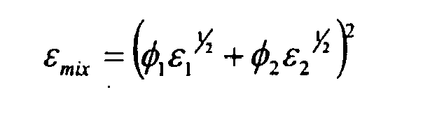
- The dielectric constant of the mixture is dependent upon the volume fraction, φ, of the mixture constituents multiplied times the square root of the dielectric constant, ε, of that constituent added to a similar factor for each constituent in the mixture. The sum of these terms is squared to give the resulting dielectric constant of the mixture.
- Steam quality is measured in terms of the mass ratio of steam to dispersed liquid water. Thus it is necessary to express steam quality in terms of volume by taking into account the density of the steam, ρ s , and that of the water, ρ w . Steam density is determined by temperature and pressure. Liquid water density depends on temperature. Thus for steam, a mixing equation for the dielectric constant depending upon steam quality Q is:

- For this simple analysis, consider steam at 153.010 pounds per square inch (psi). For this pressure of steam, the temperature is found to be approximately 360 degrees F. The specific volume of steam under these conditions is 2.9573. The specific volume of liquid water at this same temperature is 0.01811. Page E-57 of the Handbook of Chemistry and Physics gives the static dielectric constant of water as 38.21 via interpolation for these conditions. As a worst-case condition, the highest reported value of the dielectric constant of steam will be used to analyze the required sensitivity of the measurement sensor. At 100 degrees Celsius, steam is reported to have a dielectric constant of 1.0126. The value for 140 degrees C is 1.00785. Figure 9 is a plot of the value of ε Q for these parameter values over the entire range of steam quality from 0 to 100%.
- One observes from Figure 9 that the change in dielectric value for a large portion of the range in quality values, for example from 50 to 100%, is very small. Figure 10 expands the plot over this range of quality values, and illustrates that a sensor with adequate resolution could indeed provide a measure of steam quality. Prior art microwave sensors do not have adequate resolution to make a reliable measurement of steam quality over this important range of values. Consider, for example, a sensor designed to measure dielectric constant based upon the phase shift of a wave traveling through such a steam/water mixture.
- To compute the phase shift that would be experienced by a wave traveling along a transmission line having steam as the surrounding dielectric versus a wave traveling in free space, the amount of phase shift will depend upon the length of the line and the frequency of the energy. The graph in Figure 11 shows the total amount of phase shift difference that can be expected for a line that is 3 inches in length at a frequency of 10.525 GHz. The graph clearly reveals to those skilled in the art that a simple phase shift measurement is not sensitive enough to do a good job of measuring steam quality in the 50% to 100% range. Phase shift measurements, at the very best, can be achieved to an accuracy of plus or minus a few degrees.
- Advantageously, the total frequency shift for 50 to 100% quality steam using the sensor designed according to the present invention is shown in Figure 12A and Figure 12B. Those skilled in the art will readily recognize and appreciate that a very precise measurement of steam quality is afforded by measuring the "null frequency". Based upon readily available methods for generating microwave frequencies and the readily available methods for measuring such "null" frequencies, as it was shown previously, the steam quality can be measured to a precision of plus or minus 0.0156 %, a very high resolution.
- The present invention derives technical advantages by having application to a wide range of measurement problems. The preferred embodiment described, as illustrated for the steam quality sensor, is itself useful for numerous applications other than steam quality, particularly those applications for which large changes in substance properties result in relatively small changes in electrical parameters or the dielectric properties are near that of air, including wet gas measurement, gas composition measurement, bag breakout monitoring, dryer completion monitoring, moisture content in pneumatically conveyed materials, measurement of fly ash percentage in stack gases, etc. For applications involving higher dielectric constants or materials that have much larger losses associated with a signal passing through the material, other embodiments are contemplated.
- The operating frequency and the difference in transmission path length may not be selected independently. Here the term "operating frequency" refers to the frequency for which a null output condition is produced for a given value of dielectric constant. If the operating frequency is given, then the transmission path length is generally fixed by the electrical properties of the material under test. A simple relationship exists between the operating frequency,f, and the relative dielectric constant, εr, and the difference in path length, ΔL, and the number of half wavelengths, n, represented by the ΔL value according to the following equation:

where c is the speed of light in vacuum. This relationship is referred by the inventors as Delta-L(ΔL) technology. This expression assumes a TEM wave traveling along the transmission lines. For other modes of propagation, such as in a waveguide, the expression requires modification such that the speed of light, c, is replaced with the vacuum velocity of that particular mode. - The range in dielectric constant values that are to be measured by the sensor determines the required bandwidth of the
signal source 110. Some flexibility is possible in constraining the required bandwidth. It is possible to switch in and out various lengths of transmission line to effectively adjust the phase of the signal on one of the transmission paths with respect to the other, so that the frequency required to produce the null is modified by the change in the length of the line. It is contemplated within the scope of the present invention that a lower cost version of the sensor could incorporate switchable sections of line, perhaps varying by factors of two to facilitate a digital representation of the inserted length, so that a relatively narrowbandwidth frequency source 110 could accommodate a large variation in dielectric constant for the process material under test. - It will be appreciated by those skilled in the art that many other configurations are possible which accomplish the same fundamental teaching of the present invention. Another such variation in the structure of the transmission lines is to make the insertion depth for two lines comprising a probe-type implementation to be equal, but causing the electrical lengths of the lines to differ by having one line follow a slightly serpentine path from the entry port to the end of the probe structure. Such a structure will have a response corresponding the material properties averaged along the full length of the probe, whereas two lines extending in to different depths will be more tip sensitive. Again, many options are possible for achieving the fundamental teaching and all of these are included in the choices contemplated not only for the various embodiments that are specifically mentioned in this specification, but also for those embodiments that are suggested here.
- Among the potential applications contemplated for the present invention for which the teaching of the invention offers significant performance or cost advantages, in addition to the applications already noted, are the following:
- Measuring any material parameter that may be inferred from measuring the electrical properties of the material.
- Monitoring and controlling blending processes, for example, the mixture of gasoline with methanol, or for putting specific amounts of ether into gasoline to increase the octane, or mixing together meats having differing fat content to achieve a mixture of a specified fat value.
- Measuring the moisture in powders, such as, for example, pneumatic conveying applications, grains, plastic pellets, pulverized coal and the like.
- Monitoring and controlling the operation of a drying operation by measuring the moisture in the exhaust gases of a drier.
- Measuring pulp stock consistency.
- Measuring the concentration of various solid materials entrained in a liquid or gas.
- Monitoring the purity of various pure liquids and gases.
- Measuring the moisture in various food products such as doughs, batters, cheeses, and the like.
- Measuring the fat content in various food products such as processed meat, ground meat, milk, and the like.
- Measuring the moisture in various gases.
- Measuring the moisture in hydrocarbons.
- Detecting the interface between products being transported in a pipeline.
- Determining the state of or percent completion of a chemical reaction.
- Though the invention has been described with respect to a specific preferred embodiment, many variations and modifications will become apparent to those skilled in the art upon reading the present application. It is therefore the intention that the appended claims be interpreted as broadly as possible in view of the prior art to include all such variations and modifications. The overall length of the signal paths will influence the sensitivity of the loss factor measurement.
Claims (8)
- A sensor (10) employing microwave electromagnetic energy for determining a characteristic of a substance, comprising:a first transmission line (12) in the form of a single conductor (16) suspended above a ground plane (20) adapted to communicate electromagnetic energy through the substance along the first line and having a first electrical distance and a first physical length;a second transmission line (14) in the form of a single conductor (18) suspended above the ground plane (20) adapted to communicate electromagnetic energy along the second line having a second electrical distance and a second physical length, said second electrical distance being different by a dimension ΔL from said first electrical distance;a common ground plane conductor (20) shared by both transmission lines each transmission terminating in a short circuit at said ground plane to form a reflecting termination for each transmission line;a signal generator electrically coupled to both said first transmssion line (12) and said second transmission line (14) and generating an excitation signal at different frequencies, said excitation signal for producing electromagnetic energy communicable through the substance; anda signal detector electrically coupled to both said first transmission line (12) and said second transmission line (14) adapted to combine the signals from the two transmission lines so as to produce interference and to thus detect a signal resulting from electromagnetic energy communicated through the substance; said resulting signal exhibiting a characteristic indicative of the difference in said first and second electrical distances as influenced by the substance.
- The sensor of claim 1, wherein a portion of said single conductor of said first physical length is coated with a dielectric material.
- The sensor of claim 1, wherein the sensor forms a completely sealed probe suitable for a portable version of the sensor for applications such as the sampled measurement of the percent fat in processed or ground meat.
- The sensor of claim 1, wherein said conductors penetrate the probe's mounting flange and are insulated by a dielectric material that also seals the space around each conductor.
- The sensor of claim 1, wherein said first and second conductors extend through the wall of a pipe containing the substance.
- A method employing microwave electromagnetic energy for determining a characteristic of a substance, comprising:providing a first transmission line (12) in the form of a single conductor suspended above a ground plane; said first transmission line adapted to communicate electromagnetic energy through the substance along the first transmission line and having a first electrical distance and a first physical length;providing a second transmission line (14) in the form of a single conductor suspended above the ground plane, said second transmission line having a second electrical distance and a second physical length, said second electrical distance being different by a dimension ΔL from said first electrical distance;providing a ground plane conductor (20) shared by both transmission lines each transmission line terminating in a short circuit at said ground plane (20) to form a reflecting termination for each transmission line;providing a signal generator electrically coupled to both said first transmission line and said second transmission line and generating an excitation signal at different frequencies, said excitation signal for producing electromagnetic energy communicable through the substance; andproviding a signal detector electrically coupled to both said first transmission line and said second transmission line adapted to combine the signals from the two transmission lines so as to produce interference and to thus detect a signal resulting from electromagnetic energy communicated through the substance; said resulting signal exhibiting a characteristic indicative of the difference in said first and second electrical distances as influenced by the substance.
- The method of claim 6, wherein a portion of said single conductor of said first physical length is coated with a dielectric material (80).
- The method of claim 6, wherein said conductors penetrate the probe's mounting flange and are insulated by a dielectric material that also seals the space around each conductor.
Applications Claiming Priority (3)
| Application Number | Priority Date | Filing Date | Title |
|---|---|---|---|
| US16644599P | 1999-11-19 | 1999-11-19 | |
| US166445P | 1999-11-19 | ||
| PCT/US2000/031851 WO2001036951A2 (en) | 1999-11-19 | 2000-11-20 | Interferometric microwave sensor |
Publications (2)
| Publication Number | Publication Date |
|---|---|
| EP1242812A2 EP1242812A2 (en) | 2002-09-25 |
| EP1242812B1 true EP1242812B1 (en) | 2007-05-09 |
Family
ID=22603336
Family Applications (1)
| Application Number | Title | Priority Date | Filing Date |
|---|---|---|---|
| EP00980562A Expired - Lifetime EP1242812B1 (en) | 1999-11-19 | 2000-11-20 | Interferometric microwave sensor |
Country Status (9)
| Country | Link |
|---|---|
| US (1) | US6614238B1 (en) |
| EP (1) | EP1242812B1 (en) |
| JP (1) | JP2003515130A (en) |
| AR (1) | AR029017A1 (en) |
| AT (1) | ATE362104T1 (en) |
| AU (1) | AU776712B2 (en) |
| CA (1) | CA2391981C (en) |
| DE (1) | DE60034811T2 (en) |
| WO (1) | WO2001036951A2 (en) |
Families Citing this family (26)
| Publication number | Priority date | Publication date | Assignee | Title |
|---|---|---|---|---|
| US6782328B2 (en) * | 1999-01-21 | 2004-08-24 | Rosemount Inc. | Measurement of concentration of material in a process fluid |
| DE10164107C1 (en) * | 2001-12-24 | 2003-09-18 | Promecon Prozess & Messtechnik | Microwave measuring device for determining the loading of a two-phase flow |
| FR2853415B1 (en) * | 2003-04-04 | 2007-01-12 | Inst Francais Du Petrole | METHOD FOR DETERMINING THE COMPOSITION OF A HOMOGENEOUS FLUID |
| US7140238B2 (en) | 2003-04-04 | 2006-11-28 | Institut Francais Du Petrole | Method for determining the composition of a fluid |
| US7135870B2 (en) * | 2004-05-04 | 2006-11-14 | Kam Controls Incorporated | Device for determining the composition of a fluid mixture |
| US7236120B2 (en) * | 2005-03-31 | 2007-06-26 | United States Of America As Represented By The Secretary Of Commerce, The National Institute Of Standards And Technology | Ultra-wideband detector systems for detecting moisture in building walls |
| CN100434002C (en) * | 2005-07-09 | 2008-11-19 | 胡海洋 | Method for measuring cut tobacco in air pipeline for cigarette machine and cut tobacco metering control instrument |
| US7281412B2 (en) * | 2005-09-08 | 2007-10-16 | Olenick John A | In-situ seal integrity monitoring |
| US7345280B2 (en) | 2005-09-29 | 2008-03-18 | General Electric Company | Measurement of steam quality using multiple broadband lasers |
| US7381954B2 (en) | 2005-09-29 | 2008-06-03 | General Electric Company | Apparatus and method for measuring steam quality |
| NO324812B1 (en) * | 2006-05-05 | 2007-12-10 | Multi Phase Meters As | Method and apparatus for tomographic multiphase flow measurements |
| US8647272B2 (en) * | 2007-06-21 | 2014-02-11 | Rf Science & Technology Inc | Non-invasive scanning apparatuses |
| US8259299B2 (en) | 2007-06-21 | 2012-09-04 | Rf Science & Technology Inc. | Gas scanning and analysis |
| US8382668B2 (en) * | 2007-06-21 | 2013-02-26 | Rf Science & Technology Inc. | Non-invasive determination of characteristics of a sample |
| US8647273B2 (en) * | 2007-06-21 | 2014-02-11 | RF Science & Technology, Inc. | Non-invasive weight and performance management |
| US10264993B2 (en) * | 2007-06-21 | 2019-04-23 | Rf Science & Technology Inc. | Sample scanning and analysis system and methods for using the same |
| NO330911B1 (en) | 2008-12-12 | 2011-08-15 | Multi Phase Meters As | Method and apparatus for measuring composition and flow rates for a wet gas |
| NO334550B1 (en) | 2008-12-12 | 2014-04-07 | Multi Phase Meters As | Method and apparatus for flow measurements for a wet gas and gas value measurements |
| US8028588B2 (en) * | 2009-09-25 | 2011-10-04 | Rosemount Inc. | Flow measurement using near field microwaves |
| US10607507B2 (en) | 2015-11-24 | 2020-03-31 | Medibotics | Arcuate wearable device with a circumferential or annular array of spectroscopic sensors for measuring hydration level |
| US9109995B2 (en) | 2012-10-16 | 2015-08-18 | Kam Controls, Inc. | Method and apparatus for determining the water concentration in a fluid mixture |
| EP2669661A1 (en) * | 2012-11-06 | 2013-12-04 | Siemens Aktiengesellschaft | Method and device to determine the volume ratio of at least two components in a mixture |
| JP5942912B2 (en) * | 2013-03-27 | 2016-06-29 | 株式会社デンソーウェーブ | Water content estimation system, wireless tag reader |
| US9244049B2 (en) * | 2013-05-07 | 2016-01-26 | General Electric Company | System and method for detection of nutritional parameters in food items |
| NO20140689A1 (en) * | 2014-06-03 | 2015-12-04 | Roxar Flow Measurement As | Cutoff regulator |
| DE102020003382B4 (en) * | 2020-06-04 | 2023-02-23 | Plantcare Ag | Moisture measuring device with antibacterial effect |
Citations (4)
| Publication number | Priority date | Publication date | Assignee | Title |
|---|---|---|---|---|
| JPS6176964A (en) * | 1984-09-21 | 1986-04-19 | Nec Corp | Measuring method of high frequency dielectric characteristic of thin film insulator |
| US5136249A (en) * | 1988-06-20 | 1992-08-04 | Commonwealth Scientific & Industrial Research Organization | Probes for measurement of moisture content, solids contents, and electrical conductivity |
| US5363052A (en) * | 1993-02-16 | 1994-11-08 | Solid State Farms, Inc. | Permittivity spectroscopy apparatus and method |
| WO1995003542A1 (en) * | 1993-07-26 | 1995-02-02 | Phase Dynamics, Inc. | System and method for monitoring substances and reactions |
Family Cites Families (22)
| Publication number | Priority date | Publication date | Assignee | Title |
|---|---|---|---|---|
| FR1312022A (en) * | 1961-11-03 | 1962-12-14 | Euratom | Method of automatic measurement of a phase shift and apparatus by applying |
| GB1078111A (en) * | 1963-02-13 | 1967-08-02 | Microwave Instr Ltd | Improvements in or relating to the detection and measurement of water vapour in gases |
| US3403335A (en) * | 1965-05-19 | 1968-09-24 | Amp Inc | Dielectric constant measurement means and method utilizing frequency sweep and fixed probe |
| GB1078504A (en) * | 1965-06-25 | 1967-08-09 | Microwave Instr Ltd | Apparatus for and a method of moisture measurement in highly viscous pastes and similar materials |
| SE418774B (en) * | 1976-03-22 | 1981-06-22 | Innotec Oy | DEVICE FOR INDICATING THE TRANSMISSION THROUGH OR THROUGH THE REFLECTING RADIO-FREQUENCY ENERGY'S sudden change |
| US4217565A (en) * | 1978-12-26 | 1980-08-12 | Edward Salzberg | Hybrid T-junction switch |
| US4544880A (en) * | 1982-04-28 | 1985-10-01 | General Motors Corporation | Microwave probe for measurement of dielectric constants |
| DE3412704A1 (en) * | 1983-04-06 | 1984-10-11 | Nippondenso Co., Ltd., Kariya, Aichi | DEVICE FOR MEASURING THE ALCOHOL CONTENT IN FUEL MIXTURES |
| JPS607347A (en) * | 1983-06-28 | 1985-01-16 | Nippon Denso Co Ltd | Gas concentration sensor |
| US4902961A (en) * | 1987-04-08 | 1990-02-20 | Chevron Research Company | Microwave system for monitoring water content in a petroleum pipeline |
| US5103181A (en) * | 1988-10-05 | 1992-04-07 | Den Norske Oljeselskap A. S. | Composition monitor and monitoring process using impedance measurements |
| US4996489A (en) | 1989-03-31 | 1991-02-26 | Halliburton Logging Services, Inc. | Laboratory technique for measuring complex dielectric constant of rock core samples |
| US5101163A (en) * | 1989-10-04 | 1992-03-31 | Agar Corporation Ltd. | Oil/water measurement |
| US5073755A (en) * | 1990-03-19 | 1991-12-17 | Mpr Teltech Ltd. | Method and apparatus for measuring the electrical properties of dielectric film in the gigahertz range |
| CA2022702C (en) * | 1990-08-03 | 1995-02-07 | Frank B. Walton | Method and apparatus for detecting soot concentration in particulate trap |
| US5334941A (en) * | 1992-09-14 | 1994-08-02 | Kdc Technology Corp. | Microwave reflection resonator sensors |
| JP3124413B2 (en) * | 1993-06-17 | 2001-01-15 | 株式会社神戸製鋼所 | Semiconductor wafer minority carrier lifetime measurement system |
| US5933014A (en) * | 1994-11-23 | 1999-08-03 | Fraunhofer Gesellschaft Zur Foerderung | Process for detecting totally or partially hidden non-homogeneities by means of microwave radiation |
| DE19504544A1 (en) * | 1995-02-11 | 1996-08-14 | Reich Ernst | Method for determining the loading of a gas stream with solid components |
| EP0852705A1 (en) * | 1995-09-29 | 1998-07-15 | Rosemount Inc. | Microwave waveguide for tank level sensors |
| US5741979A (en) * | 1995-11-09 | 1998-04-21 | The United States Of America As Represented By The Administrator Of National Aeronautics And Space Adminstrator | Particle velocity measuring system |
| US6275738B1 (en) * | 1999-08-19 | 2001-08-14 | Kai Technologies, Inc. | Microwave devices for medical hyperthermia, thermotherapy and diagnosis |
-
2000
- 2000-11-20 DE DE60034811T patent/DE60034811T2/en not_active Expired - Fee Related
- 2000-11-20 US US09/716,748 patent/US6614238B1/en not_active Expired - Fee Related
- 2000-11-20 CA CA002391981A patent/CA2391981C/en not_active Expired - Fee Related
- 2000-11-20 JP JP2001538789A patent/JP2003515130A/en active Pending
- 2000-11-20 AT AT00980562T patent/ATE362104T1/en not_active IP Right Cessation
- 2000-11-20 AU AU17810/01A patent/AU776712B2/en not_active Ceased
- 2000-11-20 WO PCT/US2000/031851 patent/WO2001036951A2/en not_active Ceased
- 2000-11-20 EP EP00980562A patent/EP1242812B1/en not_active Expired - Lifetime
- 2000-11-21 AR ARP000106127A patent/AR029017A1/en unknown
Patent Citations (4)
| Publication number | Priority date | Publication date | Assignee | Title |
|---|---|---|---|---|
| JPS6176964A (en) * | 1984-09-21 | 1986-04-19 | Nec Corp | Measuring method of high frequency dielectric characteristic of thin film insulator |
| US5136249A (en) * | 1988-06-20 | 1992-08-04 | Commonwealth Scientific & Industrial Research Organization | Probes for measurement of moisture content, solids contents, and electrical conductivity |
| US5363052A (en) * | 1993-02-16 | 1994-11-08 | Solid State Farms, Inc. | Permittivity spectroscopy apparatus and method |
| WO1995003542A1 (en) * | 1993-07-26 | 1995-02-02 | Phase Dynamics, Inc. | System and method for monitoring substances and reactions |
Non-Patent Citations (3)
| Title |
|---|
| A. GÖLLER: "Design und Anwendungen von Mikrowellen-Applikatoren", MATERIALFEUCHTEMESSUNG: GRUNDLAGEN, MESSVERFAHREN, APPLIKATIONEN, NORMEN, 1997, RENNINGEN-MALMSHEIM, GERMANY, pages 155 - 164, ISBN: 3-8169-1359-8 * |
| MICHAEL D. JANEZIC AND JEFFREY A. JARGON: "COMPLEX PERMITTIVITY DETERMINATION FROM PROPAGATION CONSTANT MEASUREMENTS", IEEE MICROWAVE AND GUIDED WAVE LETTERS, vol. 9, no. 2, February 1999 (1999-02-01), pages 76 - 78, XP011035411 * |
| R. KNÖCHEL: "Messverfahren zur Erfassung der Kenngrössen des Mikrowellenfeldes", MATERIALFEUCHTEMESSUNG: GRUNDLAGEN, MESSVERFAHREN, APPLIKATIONEN, NORMEN, 1997, RENNINGEN-MALMSHEIM, GERMANY, pages 165 - 173, ISBN: 3-8169-1359-8 * |
Also Published As
| Publication number | Publication date |
|---|---|
| WO2001036951A3 (en) | 2002-06-20 |
| ATE362104T1 (en) | 2007-06-15 |
| JP2003515130A (en) | 2003-04-22 |
| AU1781001A (en) | 2001-05-30 |
| EP1242812A2 (en) | 2002-09-25 |
| WO2001036951A2 (en) | 2001-05-25 |
| AU776712B2 (en) | 2004-09-16 |
| AR029017A1 (en) | 2003-06-04 |
| CA2391981A1 (en) | 2001-05-25 |
| DE60034811D1 (en) | 2007-06-21 |
| CA2391981C (en) | 2005-11-01 |
| US6614238B1 (en) | 2003-09-02 |
| DE60034811T2 (en) | 2008-01-24 |
Similar Documents
| Publication | Publication Date | Title |
|---|---|---|
| US6614238B1 (en) | Microwave sensor having improved sensitivity | |
| AU677201B2 (en) | Meter and method for in situ measurement of the electro- magnetic properties of various process materials using cutoff frequency characterization and analysis | |
| US5331284A (en) | Meter and method for in situ measurement of the electromagnetic properties of various process materials using cutoff frequency characterization and analysis | |
| Nyfors | Industrial microwave sensors—A review | |
| US6691563B1 (en) | Universal dielectric calibration method and apparatus for moisture content determination in particulate and granular materials | |
| Trabelsi et al. | Density-independent functions for on-line microwave moisture meters: a general discussion | |
| CN101614681B (en) | Micro-water content test system based on resonant cavity perturbation method | |
| US8076950B2 (en) | Method and apparatus for measuring the water conductivity and water volume fraction of a multiphase mixture containing water | |
| EP1112485B1 (en) | An apparatus and method for measuring and monitoring complex permittivity of materials | |
| EP0962761A2 (en) | Oil/water measurement | |
| WO1990004167A1 (en) | Composition monitor and monitoring process using impedance measurements | |
| CN105026919B (en) | For the sensor and method of the dielectric property for determining medium | |
| GB2313914A (en) | Sub-surface formation fluid tester | |
| Shang et al. | A complex permittivity measurement system for undisturbed/compacted soils | |
| Abd Rahman et al. | Planar microwave sensors for accurate measurement of material characterization: A review | |
| Raveendranath et al. | Broadband coaxial cavity resonator for complex permittivity measurements of liquids | |
| Will et al. | Comparative study of moisture measurements by time domain transmissometry | |
| US6930492B2 (en) | Using surface microwaves for measuring and determining density and/or moisture content of a material | |
| Stuchly et al. | State of the art in microwave sensors for measuring non-electrical quantities | |
| Yadav et al. | A Microwave Sensor for Grain Moisture-Content Measurement Designed with Surface Wave Transmission Line | |
| Jean | Process composition monitoring at microwave frequencies: A waveguide cutoff method and calibration procedure | |
| WO2026044421A1 (en) | Use of a transverse electromagnetic cell for measuring the electrical characteristics of flowing granular materials | |
| Moolat et al. | Non-invasive Measurement of Complex permittivity using a Compact Planar Microwave Sensor | |
| Bier et al. | A low-cost microwave-based sensor for water content detection | |
| CN117347307A (en) | Terahertz detection device and detection method |
Legal Events
| Date | Code | Title | Description |
|---|---|---|---|
| PUAI | Public reference made under article 153(3) epc to a published international application that has entered the european phase |
Free format text: ORIGINAL CODE: 0009012 |
|
| AK | Designated contracting states |
Kind code of ref document: A2 Designated state(s): AT BE CH CY DE DK ES FI FR GB GR IE IT LI LU MC NL PT SE TR |
|
| AX | Request for extension of the european patent |
Free format text: AL;LT;LV;MK;RO;SI |
|
| 17P | Request for examination filed |
Effective date: 20020618 |
|
| 17Q | First examination report despatched |
Effective date: 20041102 |
|
| GRAP | Despatch of communication of intention to grant a patent |
Free format text: ORIGINAL CODE: EPIDOSNIGR1 |
|
| GRAS | Grant fee paid |
Free format text: ORIGINAL CODE: EPIDOSNIGR3 |
|
| GRAA | (expected) grant |
Free format text: ORIGINAL CODE: 0009210 |
|
| AK | Designated contracting states |
Kind code of ref document: B1 Designated state(s): AT BE CH CY DE DK ES FI FR GB GR IE IT LI LU MC NL PT SE TR |
|
| PG25 | Lapsed in a contracting state [announced via postgrant information from national office to epo] |
Ref country code: LI Free format text: LAPSE BECAUSE OF FAILURE TO SUBMIT A TRANSLATION OF THE DESCRIPTION OR TO PAY THE FEE WITHIN THE PRESCRIBED TIME-LIMIT Effective date: 20070509 Ref country code: FI Free format text: LAPSE BECAUSE OF FAILURE TO SUBMIT A TRANSLATION OF THE DESCRIPTION OR TO PAY THE FEE WITHIN THE PRESCRIBED TIME-LIMIT Effective date: 20070509 Ref country code: CH Free format text: LAPSE BECAUSE OF FAILURE TO SUBMIT A TRANSLATION OF THE DESCRIPTION OR TO PAY THE FEE WITHIN THE PRESCRIBED TIME-LIMIT Effective date: 20070509 |
|
| REG | Reference to a national code |
Ref country code: GB Ref legal event code: FG4D |
|
| REG | Reference to a national code |
Ref country code: CH Ref legal event code: EP |
|
| REG | Reference to a national code |
Ref country code: IE Ref legal event code: FG4D |
|
| REF | Corresponds to: |
Ref document number: 60034811 Country of ref document: DE Date of ref document: 20070621 Kind code of ref document: P |
|
| PG25 | Lapsed in a contracting state [announced via postgrant information from national office to epo] |
Ref country code: SE Free format text: LAPSE BECAUSE OF FAILURE TO SUBMIT A TRANSLATION OF THE DESCRIPTION OR TO PAY THE FEE WITHIN THE PRESCRIBED TIME-LIMIT Effective date: 20070809 |
|
| PG25 | Lapsed in a contracting state [announced via postgrant information from national office to epo] |
Ref country code: ES Free format text: LAPSE BECAUSE OF FAILURE TO SUBMIT A TRANSLATION OF THE DESCRIPTION OR TO PAY THE FEE WITHIN THE PRESCRIBED TIME-LIMIT Effective date: 20070820 |
|
| NLV1 | Nl: lapsed or annulled due to failure to fulfill the requirements of art. 29p and 29m of the patents act | ||
| ET | Fr: translation filed | ||
| REG | Reference to a national code |
Ref country code: CH Ref legal event code: PL |
|
| PG25 | Lapsed in a contracting state [announced via postgrant information from national office to epo] |
Ref country code: AT Free format text: LAPSE BECAUSE OF FAILURE TO SUBMIT A TRANSLATION OF THE DESCRIPTION OR TO PAY THE FEE WITHIN THE PRESCRIBED TIME-LIMIT Effective date: 20070509 |
|
| PG25 | Lapsed in a contracting state [announced via postgrant information from national office to epo] |
Ref country code: BE Free format text: LAPSE BECAUSE OF FAILURE TO SUBMIT A TRANSLATION OF THE DESCRIPTION OR TO PAY THE FEE WITHIN THE PRESCRIBED TIME-LIMIT Effective date: 20070509 |
|
| PG25 | Lapsed in a contracting state [announced via postgrant information from national office to epo] |
Ref country code: PT Free format text: LAPSE BECAUSE OF FAILURE TO SUBMIT A TRANSLATION OF THE DESCRIPTION OR TO PAY THE FEE WITHIN THE PRESCRIBED TIME-LIMIT Effective date: 20071009 Ref country code: NL Free format text: LAPSE BECAUSE OF FAILURE TO SUBMIT A TRANSLATION OF THE DESCRIPTION OR TO PAY THE FEE WITHIN THE PRESCRIBED TIME-LIMIT Effective date: 20070509 Ref country code: DK Free format text: LAPSE BECAUSE OF FAILURE TO SUBMIT A TRANSLATION OF THE DESCRIPTION OR TO PAY THE FEE WITHIN THE PRESCRIBED TIME-LIMIT Effective date: 20070509 |
|
| PLBE | No opposition filed within time limit |
Free format text: ORIGINAL CODE: 0009261 |
|
| STAA | Information on the status of an ep patent application or granted ep patent |
Free format text: STATUS: NO OPPOSITION FILED WITHIN TIME LIMIT |
|
| 26N | No opposition filed |
Effective date: 20080212 |
|
| PG25 | Lapsed in a contracting state [announced via postgrant information from national office to epo] |
Ref country code: GR Free format text: LAPSE BECAUSE OF FAILURE TO SUBMIT A TRANSLATION OF THE DESCRIPTION OR TO PAY THE FEE WITHIN THE PRESCRIBED TIME-LIMIT Effective date: 20070810 Ref country code: IT Free format text: LAPSE BECAUSE OF FAILURE TO SUBMIT A TRANSLATION OF THE DESCRIPTION OR TO PAY THE FEE WITHIN THE PRESCRIBED TIME-LIMIT Effective date: 20070509 |
|
| PGFP | Annual fee paid to national office [announced via postgrant information from national office to epo] |
Ref country code: FR Payment date: 20071120 Year of fee payment: 8 Ref country code: GB Payment date: 20071123 Year of fee payment: 8 |
|
| PGFP | Annual fee paid to national office [announced via postgrant information from national office to epo] |
Ref country code: DE Payment date: 20080131 Year of fee payment: 8 |
|
| PG25 | Lapsed in a contracting state [announced via postgrant information from national office to epo] |
Ref country code: MC Free format text: LAPSE BECAUSE OF NON-PAYMENT OF DUE FEES Effective date: 20071130 |
|
| PG25 | Lapsed in a contracting state [announced via postgrant information from national office to epo] |
Ref country code: IE Free format text: LAPSE BECAUSE OF NON-PAYMENT OF DUE FEES Effective date: 20071120 |
|
| GBPC | Gb: european patent ceased through non-payment of renewal fee |
Effective date: 20081120 |
|
| PG25 | Lapsed in a contracting state [announced via postgrant information from national office to epo] |
Ref country code: CY Free format text: LAPSE BECAUSE OF FAILURE TO SUBMIT A TRANSLATION OF THE DESCRIPTION OR TO PAY THE FEE WITHIN THE PRESCRIBED TIME-LIMIT Effective date: 20070509 |
|
| PG25 | Lapsed in a contracting state [announced via postgrant information from national office to epo] |
Ref country code: LU Free format text: LAPSE BECAUSE OF NON-PAYMENT OF DUE FEES Effective date: 20071120 |
|
| REG | Reference to a national code |
Ref country code: FR Ref legal event code: ST Effective date: 20090731 |
|
| PG25 | Lapsed in a contracting state [announced via postgrant information from national office to epo] |
Ref country code: TR Free format text: LAPSE BECAUSE OF FAILURE TO SUBMIT A TRANSLATION OF THE DESCRIPTION OR TO PAY THE FEE WITHIN THE PRESCRIBED TIME-LIMIT Effective date: 20070509 |
|
| PG25 | Lapsed in a contracting state [announced via postgrant information from national office to epo] |
Ref country code: DE Free format text: LAPSE BECAUSE OF NON-PAYMENT OF DUE FEES Effective date: 20090603 |
|
| PG25 | Lapsed in a contracting state [announced via postgrant information from national office to epo] |
Ref country code: GB Free format text: LAPSE BECAUSE OF NON-PAYMENT OF DUE FEES Effective date: 20081120 |
|
| PG25 | Lapsed in a contracting state [announced via postgrant information from national office to epo] |
Ref country code: FR Free format text: LAPSE BECAUSE OF NON-PAYMENT OF DUE FEES Effective date: 20081130 |