EP1241915A1 - Methods and devices for providing optical, service-enabled cross-connections - Google Patents
Methods and devices for providing optical, service-enabled cross-connections Download PDFInfo
- Publication number
- EP1241915A1 EP1241915A1 EP02251577A EP02251577A EP1241915A1 EP 1241915 A1 EP1241915 A1 EP 1241915A1 EP 02251577 A EP02251577 A EP 02251577A EP 02251577 A EP02251577 A EP 02251577A EP 1241915 A1 EP1241915 A1 EP 1241915A1
- Authority
- EP
- European Patent Office
- Prior art keywords
- optical
- units
- signal
- switch
- processing
- Prior art date
- Legal status (The legal status is an assumption and is not a legal conclusion. Google has not performed a legal analysis and makes no representation as to the accuracy of the status listed.)
- Ceased
Links
- 230000003287 optical effect Effects 0.000 title claims abstract description 38
- 238000000034 method Methods 0.000 title claims abstract description 16
- 238000012545 processing Methods 0.000 claims abstract description 40
- 238000001069 Raman spectroscopy Methods 0.000 claims abstract description 8
- 239000006185 dispersion Substances 0.000 claims abstract description 6
- 238000012544 monitoring process Methods 0.000 abstract description 3
- 238000005086 pumping Methods 0.000 abstract description 2
- 230000008929 regeneration Effects 0.000 abstract description 2
- 238000011069 regeneration method Methods 0.000 abstract description 2
- 230000037361 pathway Effects 0.000 description 5
- 230000008569 process Effects 0.000 description 5
- 230000008901 benefit Effects 0.000 description 4
- 238000006243 chemical reaction Methods 0.000 description 3
- 238000013461 design Methods 0.000 description 3
- 238000004891 communication Methods 0.000 description 2
- 239000000835 fiber Substances 0.000 description 2
- 239000013307 optical fiber Substances 0.000 description 2
- 230000003321 amplification Effects 0.000 description 1
- 238000013459 approach Methods 0.000 description 1
- 230000008859 change Effects 0.000 description 1
- 230000000694 effects Effects 0.000 description 1
- 238000005516 engineering process Methods 0.000 description 1
- RGNPBRKPHBKNKX-UHFFFAOYSA-N hexaflumuron Chemical group C1=C(Cl)C(OC(F)(F)C(F)F)=C(Cl)C=C1NC(=O)NC(=O)C1=C(F)C=CC=C1F RGNPBRKPHBKNKX-UHFFFAOYSA-N 0.000 description 1
- 238000007726 management method Methods 0.000 description 1
- 238000003199 nucleic acid amplification method Methods 0.000 description 1
- 230000009467 reduction Effects 0.000 description 1
- 238000012360 testing method Methods 0.000 description 1
- 239000002699 waste material Substances 0.000 description 1
Images
Classifications
-
- H—ELECTRICITY
- H04—ELECTRIC COMMUNICATION TECHNIQUE
- H04Q—SELECTING
- H04Q11/00—Selecting arrangements for multiplex systems
- H04Q11/0001—Selecting arrangements for multiplex systems using optical switching
- H04Q11/0005—Switch and router aspects
-
- H—ELECTRICITY
- H04—ELECTRIC COMMUNICATION TECHNIQUE
- H04Q—SELECTING
- H04Q11/00—Selecting arrangements for multiplex systems
- H04Q11/0001—Selecting arrangements for multiplex systems using optical switching
- H04Q11/0005—Switch and router aspects
- H04Q2011/0037—Operation
- H04Q2011/0049—Crosstalk reduction; Noise; Power budget
-
- H—ELECTRICITY
- H04—ELECTRIC COMMUNICATION TECHNIQUE
- H04Q—SELECTING
- H04Q11/00—Selecting arrangements for multiplex systems
- H04Q11/0001—Selecting arrangements for multiplex systems using optical switching
- H04Q11/0062—Network aspects
- H04Q2011/0079—Operation or maintenance aspects
Definitions
- ULR ultra, long-reach
- ULR networks can go extremely long distances without being processed. The fewer times a signal needs to be processed, the less expensive the link will be when built and operated.
- methods and devices for improving cross-connections include an optical connection device comprising one or more optical processing units and an optical switch adapted to connect at least one of the units to one or more optical signals based on a characteristic of each signal. Only when the characteristics of the signal indicate that processing is needed is a processing unit connected to the signal. As such, units are no longer dedicated to each signal. This reduces the cost of the overall network, among other things.
- the processing unit may comprise a regenerator, Raman pump, dispersion equalization/compensation unit or a performance monitor of some sort.
- FIG. 1 One example, or embodiment, of the present invention is shown in FIG 1.
- an optical, service-enabled connection unit 10 is adapted to dynamically process one or more optical signals from one or more links d 1 , d 2-in , or d 3 based on a characteristic of each signal within links d 1 , d 2-in , or d 3 .
- signal is meant either a signal comprising a single wavelength or one comprising multiple wavelengths, multiple signals.
- connection units such as connection unit 10 envisioned by the present invention, may act as an "optical layer service node" capable of performing a wide variety of services and/or functions.
- a node is capable of providing any number of processing features, such as signal regeneration, Raman pumping, wavelength conversion, signal characteristic processing and performance monitoring (i.e., during the set-up phase of a link, etc....determining if signal processing is needed, e.g., bit error rate testing, etc%) to name a few examples.
- Connection unit 10 is shown comprising a switch 40 and a plurality of processing units 51-m, where "m" is the last unit. Taken together the processing units 51-m may be referred to as a "bank” 50 of processing units.
- the unit 10 When located at a cross-connection point the unit 10 may be referred to as a "cross-connection device" though it should be understood that units, like unit 10, envisioned by the present invention may be used at any node along a link as well.
- the optical switch 40 is adapted to dynamically connect and/or disconnect one or more of the processing units 51-m to one or more optical signals within links d 1 , d 2-in , and/or d 3 .
- the inputs and outputs corresponding with signal d 2 have been labeled d 2-in and d 2-out .
- optical switch 40 and bank 50 may be combined into a single unit or further broken down into additional units.
- the optical switch 40 is adapted to connect or disconnect one or more of the processing units 51-m to one or more of the optical signals within links d 1 , d 2-in , and/or d 3 based on characteristics of each signal.
- one unit 51-m may be connected to a single link and/or sometimes one unit 51-m may be connected to more than one link/signal at a time. Whatever the case, none of the units 51-m are solely dedicated to one link.
- the characteristics of a signal may be measured or otherwise detected by the switch 40 or, more commonly, they may be measured by other network equipment. In the latter case, once the characteristics are measured, a centralized or partially distributed network management system (not shown in FIG. 1) is adapted to send instructions or the like to switch 40 via pathway 60.
- an optical signal within links d 1 , d 2-in , or d 3 will only be processed (i.e., connected to a processing unit 51-m) if the optical switch 40 receives an instruction via pathway 60 to do so.
- any signal is a part of a link from within a ULR network it will not be connected (or disconnected) via switch 40 to a processing unit 51-m unless the ULR network sends an instruction to the optical switch 40 via pathway 60. This avoids the needless connection of an optical signal to one or more processing units 51-m.
- one or more of the signal processing units 51-m may comprise a regenerator (e.g., OEO) adapted to regenerate or "boost" the optical signal-to-noise ratio ("SNR") of signals within links d 1 , d 2-in , or d 3 .
- a regenerator e.g., OEO
- the optical switch 40 is adapted to connect and/or disconnect a processing unit 51-m to the signal, In this way, even though none of the units 51-m are dedicated to a single signal, the optical SNR of a signal may nonetheless be increased.
- this connection/disconnection is done electronically, not manually, making it a lot easier for those monitoring/maintaining such a link to connect/disconnect processing units.
- one of the optical signals may be a signal which is in need of wavelength conversion.
- the optical switch 40 may alternatively connect and disconnect a signal d 2-in to one or more processing units 51-m via pathway D IN .
- one or more of the processing units 51-m may be adapted to change the wavelength of signal d 2-in and output such a converted signal to switch 40 or another port (not shown) via pathway D OUT .
- one or more of the processing units 51-m may comprise a Raman pump adapted to amplify all signals within an optical link d 1 , d 2-in , or d 3 connected to switch 40.
- processing units 51-m may all be the same type or may comprise any number of different types of processing units. It should be further understood that the type of processing unit 51-m which is connected or disconnected by switch 40 to a given link depends on the type of characteristic needing adjustment. For example, processing units' 51-m may comprise all OEOs or a combination of Raman pumps and OEOs.
- processing units 51-m may comprise other types of processing elements such as: optical-to-optical-to-optical (“OOO") dispersion equalization/compensation units, gigabit Ethernet units, SDL units, SONET/SDH units, 2R (re-shape and re-amplify without retiming) units, 3R (re-shape and re-amplify and retime) units, to name just a few examples.
- OEO optical-to-optical-to-optical
- 3R re-shape and re-amplify and retime
- the number of optical links input into switch 40 is typically more than three and typically numbers in the hundreds or thousands. Again, though this is so it should be understood that unlike conventional systems, none of the processing units 51-m needs to be dedicated to a single signal or link. Therefore, the number of processing units 51-m can be substantially reduced. This reduction in processing units helps reduce the costs of the connection unit 10 and any network it is a part of.
- the units 51-m comprise Raman pumps or dispersion/compensation units no multiplexing/demultiplexing is needed.
- these types of units are capable of handling multiple signals of differing wavelengths from each link d 1 , d 2-in , and d 3 . It can be said that those units operate “fiber by fiber” while regenerators work “wavelength by wavelength”.
- connection unit 10 may alternatively be made a part of a "router", such as the Wavestar Lambda router made by Lucent Technologies, Inc.
- connection is meant the connection and/or disconnection of one or more of the units 51-m to one or more optical signals or links via switch 40.
Landscapes
- Engineering & Computer Science (AREA)
- Computer Networks & Wireless Communication (AREA)
- Optical Communication System (AREA)
- Use Of Switch Circuits For Exchanges And Methods Of Control Of Multiplex Exchanges (AREA)
Abstract
A technique for improving optical cross-connections comprises placing a switch (40)
in front of a number of processing units (50). So configured, the units are no longer dedicated
to a specific link or signal. When necessary, a unit is connected/disconnected to one or
more optical links by the switch to carry out any number of processing functions, such as
regeneration, Raman pumping, dispersion equalization/compensation or performance
monitoring. Because the units are no longer dedicated to specific links the cost of the
cross-connections and the network it is a part of can be reduced.
Description
- The present application claims the benefit of priority of co-pending U.S. provisional patent application No. 60/276,443 filed March 16, 2001, the disclosure of which is hereby incorporated by reference.
- Today, when voice, data or video communication signals are transmitted from one location to another the chances are high that such communications will be sent via an optical fiber network. So-called "ultra, long-reach" ("ULR") optical fiber networks are in the planning stages or just being built. ULR networks are characterized by their ability to transmit signals extremely long distances without the need to process the signals other than simple amplification.
- The advantages offered by ULR networks are many. First, signals within links of a ULR network can go extremely long distances without being processed. The fewer times a signal needs to be processed, the less expensive the link will be when built and operated.
- Because processing is not needed to be done as often, it is possible to process signals from multiple links using the same processing equipment.
- Unfortunately, the advantages offered by ULR networks have not been realized because the design of so-called electronic "cross-connection" equipment has not evolved to take these advantages into consideration. For example, existing electronic cross-connection designs still require that an individual processing unit (e.g., an optical-to-electrical-to-optical ("OEO") regenerator) be dedicated to each wavelength within a link. This is a potential waste of resources because signals within a ULR link may not need to be processed at all at any given "node."
- Utilizing existing electronic cross-connection equipment to process signals from ULR links has other inherent drawbacks. When OEOs are used, it means the optical network is not "transparent". That is, the transmitters and receivers used in such a network must be capable of sending and receiving signals compatible with one or more specific electrical/electronic-based "protocols". Only signals formatted to fit such protocols will "pass through" the network. In contrast, when OEOs are not used the network remains transparent; capable of passing any number of optical signals regardless, for the most part, of the protocol or bit rate used.
- It follows, then, that it makes little sense to utilize existing cross-connection designs to process signals from a ULR link when such processing is not needed and when such processing converts a transparent ULR link into a non-transparent link.
- Accordingly, it is a desire of the present invention to provide for methods and devices for improving optical cross-connections and nodes.
- It is also a desire of the present invention to provide for methods and devices that reduces the cost of ULR networks.
- It is yet a further desire of the present invention to provide for methods and devices that increases the transparency of ULR networks.
- Further desires will be apparent from the drawings, detailed description of the invention and claims which follow.
- In accordance with the present invention methods and devices for improving cross-connections include an optical connection device comprising one or more optical processing units and an optical switch adapted to connect at least one of the units to one or more optical signals based on a characteristic of each signal. Only when the characteristics of the signal indicate that processing is needed is a processing unit connected to the signal. As such, units are no longer dedicated to each signal. This reduces the cost of the overall network, among other things.
- The processing unit may comprise a regenerator, Raman pump, dispersion equalization/compensation unit or a performance monitor of some sort.
-
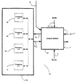
- FIG. 1 shows a technique which may be used to improve optical cross-connections according to one example or embodiment of the present invention.
-
- The present invention can best be described by referring to a number of examples which follow. While these examples will illustrate the features of the present invention, they in no way are intended to limit the scope of the present invention.
- One example, or embodiment, of the present invention is shown in FIG 1.
- As shown, an optical, service-enabled
connection unit 10 is adapted to dynamically process one or more optical signals from one or more links d1, d2-in, or d3 based on a characteristic of each signal within links d1, d2-in, or d3. It should be understood that by "signal" is meant either a signal comprising a single wavelength or one comprising multiple wavelengths, multiple signals. - As will be recognized by those skilled in the art, connection units, such as
connection unit 10 envisioned by the present invention, may act as an "optical layer service node" capable of performing a wide variety of services and/or functions. Such a node is capable of providing any number of processing features, such as signal regeneration, Raman pumping, wavelength conversion, signal characteristic processing and performance monitoring (i.e., during the set-up phase of a link, etc....determining if signal processing is needed, e.g., bit error rate testing, etc...) to name a few examples.Connection unit 10 is shown comprising aswitch 40 and a plurality of processing units 51-m, where "m" is the last unit. Taken together the processing units 51-m may be referred to as a "bank" 50 of processing units. When located at a cross-connection point theunit 10 may be referred to as a "cross-connection device" though it should be understood that units, likeunit 10, envisioned by the present invention may be used at any node along a link as well. As envisioned by the present invention theoptical switch 40 is adapted to dynamically connect and/or disconnect one or more of the processing units 51-m to one or more optical signals within links d1, d2-in, and/or d3. For ease of understanding, the inputs and outputs corresponding with signal d2 have been labeled d2-in and d2-out. - For purposes of this example, it will be assumed that all three links approach the
optical switch 40 from different directions; link d1 from the east, d2-in from the north, and d3 from the south. - Though shown as two separate units in FIG. 1, it should be understood that the
optical switch 40 andbank 50 may be combined into a single unit or further broken down into additional units. - As stated before the
optical switch 40 is adapted to connect or disconnect one or more of the processing units 51-m to one or more of the optical signals within links d1, d2-in, and/or d3 based on characteristics of each signal. Sometimes one unit 51-m may be connected to a single link and/or sometimes one unit 51-m may be connected to more than one link/signal at a time. Whatever the case, none of the units 51-m are solely dedicated to one link. - The characteristics of a signal may be measured or otherwise detected by the
switch 40 or, more commonly, they may be measured by other network equipment. In the latter case, once the characteristics are measured, a centralized or partially distributed network management system (not shown in FIG. 1) is adapted to send instructions or the like to switch 40 viapathway 60. - In an illustrative embodiment of the present invention, an optical signal within links d1, d2-in, or d3 will only be processed (i.e., connected to a processing unit 51-m) if the
optical switch 40 receives an instruction viapathway 60 to do so. In this way, if any signal is a part of a link from within a ULR network it will not be connected (or disconnected) viaswitch 40 to a processing unit 51-m unless the ULR network sends an instruction to theoptical switch 40 viapathway 60. This avoids the needless connection of an optical signal to one or more processing units 51-m. - In one embodiment of the present invention, one or more of the signal processing units 51-m may comprise a regenerator (e.g., OEO) adapted to regenerate or "boost" the optical signal-to-noise ratio ("SNR") of signals within links d1, d2-in, or d3. Thus, if the optical SNR of a signal needs to be increased, the
optical switch 40 is adapted to connect and/or disconnect a processing unit 51-m to the signal, In this way, even though none of the units 51-m are dedicated to a single signal, the optical SNR of a signal may nonetheless be increased. In one embodiment of the present invention, this connection/disconnection is done electronically, not manually, making it a lot easier for those monitoring/maintaining such a link to connect/disconnect processing units. - In a further embodiment of the present invention, one of the optical signals may be a signal which is in need of wavelength conversion. For example, the
optical switch 40 may alternatively connect and disconnect a signal d2-in to one or more processing units 51-m via pathway DIN. In turn, one or more of the processing units 51-m may be adapted to change the wavelength of signal d2-in and output such a converted signal to switch 40 or another port (not shown) via pathway DOUT. - In yet additional embodiments of the present invention, one or more of the processing units 51-m may comprise a Raman pump adapted to amplify all signals within an optical link d1, d2-in, or d3 connected to switch 40.
- It should be understood that processing units 51-m may all be the same type or may comprise any number of different types of processing units. It should be further understood that the type of processing unit 51-m which is connected or disconnected by
switch 40 to a given link depends on the type of characteristic needing adjustment. For example, processing units' 51-m may comprise all OEOs or a combination of Raman pumps and OEOs. In addition, the processing units 51-m may comprise other types of processing elements such as: optical-to-optical-to-optical ("OOO") dispersion equalization/compensation units, gigabit Ethernet units, SDL units, SONET/SDH units, 2R (re-shape and re-amplify without retiming) units, 3R (re-shape and re-amplify and retime) units, to name just a few examples. In the case where theoptical switch 40 connects an OOO to a link d1, d2-in, or d3, or where theunit 10 determines that no OEO is needed, the transparency of such a signal/link is maintained because no optical-to-electrical conversions occur. - It should be understood that the number of optical links input into
switch 40 is typically more than three and typically numbers in the hundreds or thousands. Again, though this is so it should be understood that unlike conventional systems, none of the processing units 51-m needs to be dedicated to a single signal or link. Therefore, the number of processing units 51-m can be substantially reduced. This reduction in processing units helps reduce the costs of theconnection unit 10 and any network it is a part of. - Though not shown in FIG. 1, those skilled in the art will realize that, depending on the type of processing unit 51-m making up
bank 50, multiplexing and/or demultiplexing of the signals within links d1, d2-in, and d3 may be necessary. In general, when units 51-m comprise regenerators multiplexing/demultiplexing will be required to insure a single wavelength at a time is eventually sent byswitch 40 tobank 50. This may be accomplished before signals from links d1, d2-in, or d3 are input into the switch 40 (e.g., by a separate device/unit) or may be done by the switch itself. - In contrast, when the units 51-m comprise Raman pumps or dispersion/compensation units no multiplexing/demultiplexing is needed. In effect, these types of units are capable of handling multiple signals of differing wavelengths from each link d1, d2-in, and d3. It can be said that those units operate "fiber by fiber" while regenerators work "wavelength by wavelength".
- The
connection unit 10 may alternatively be made a part of a "router", such as the Wavestar Lambda router made by Lucent Technologies, Inc. - In the claims which follow it should be understood that by "connect" is meant the connection and/or disconnection of one or more of the units 51-m to one or more optical signals or links via
switch 40. - The above discussion has given only a few examples of the present invention. Others are possible within the spirit and scope of the present invention, defined by the claims which follow:
Claims (10)
- A connection device comprising:one or more processing units; andan optical switch adapted to connect at least one of the units to one or more optical signals based on a characteristic of each signal.
- The device as in claim 1 wherein the at least one unit comprises a Raman pump.
- The device as in claim 1 wherein the at least one unit comprises an optical-to-electrical-to-optical regenerator.
- The device as in claim 1 wherein the at least one unit comprises a dispersion equalization/compensation unit.
- The device as in claim 1 wherein the at lease one unit comprises a performance monitor.
- The device as in claim 1 wherein connection unit comprises a router.
- A method for providing an optical, service-enabled connection comprising:connecting at least one of a number of processing units to one or more optical signals based on a characteristic of each signal.
- The method as in claim 7 wherein the at least one unit comprises a Raman pump.
- The method as in claim 7 wherein the at least one unit comprises an optical-to-electrical-to-optical regenerator.
- The method as in claim 7 wherein the at least one unit comprises a dispersion equalization/compensation unit.
Applications Claiming Priority (4)
| Application Number | Priority Date | Filing Date | Title |
|---|---|---|---|
| US73931 | 1998-05-06 | ||
| US27644301P | 2001-03-16 | 2001-03-16 | |
| US276443P | 2001-03-16 | ||
| US10/073,931 US7620273B2 (en) | 2001-03-16 | 2002-02-14 | Methods and devices for providing optical, serviced-enabled cross-connections |
Publications (1)
| Publication Number | Publication Date |
|---|---|
| EP1241915A1 true EP1241915A1 (en) | 2002-09-18 |
Family
ID=26755052
Family Applications (1)
| Application Number | Title | Priority Date | Filing Date |
|---|---|---|---|
| EP02251577A Ceased EP1241915A1 (en) | 2001-03-16 | 2002-03-06 | Methods and devices for providing optical, service-enabled cross-connections |
Country Status (3)
| Country | Link |
|---|---|
| US (1) | US7620273B2 (en) |
| EP (1) | EP1241915A1 (en) |
| CA (1) | CA2373959A1 (en) |
Citations (4)
| Publication number | Priority date | Publication date | Assignee | Title |
|---|---|---|---|---|
| EP0473331A2 (en) * | 1990-08-23 | 1992-03-04 | AT&T Corp. | Long distance soliton lightwave communication system |
| WO1998047039A2 (en) * | 1997-02-10 | 1998-10-22 | Optical Networks, Inc. | Method and apparatus for operation, protection, and restoration of heterogeneous optical communication networks |
| EP1009119A2 (en) * | 1998-12-10 | 2000-06-14 | Nortel Networks Corporation | Integration of Optical Add Drop Multiplexing filters |
| GB2346280A (en) * | 1998-10-22 | 2000-08-02 | Hewlett Packard Co | Optical switching interface using transponders |
Family Cites Families (3)
| Publication number | Priority date | Publication date | Assignee | Title |
|---|---|---|---|---|
| US5726788A (en) * | 1996-09-30 | 1998-03-10 | Mci Corporation | Dynamically reconfigurable optical interface device using an optically switched backplane |
| US6046833A (en) * | 1997-02-10 | 2000-04-04 | Optical Networks, Inc. | Method and apparatus for operation, protection, and restoration of heterogeneous optical communication networks |
| US6624927B1 (en) * | 2001-03-14 | 2003-09-23 | Onetta, Inc. | Raman optical amplifiers |
-
2002
- 2002-02-14 US US10/073,931 patent/US7620273B2/en not_active Expired - Lifetime
- 2002-02-28 CA CA002373959A patent/CA2373959A1/en not_active Abandoned
- 2002-03-06 EP EP02251577A patent/EP1241915A1/en not_active Ceased
Patent Citations (4)
| Publication number | Priority date | Publication date | Assignee | Title |
|---|---|---|---|---|
| EP0473331A2 (en) * | 1990-08-23 | 1992-03-04 | AT&T Corp. | Long distance soliton lightwave communication system |
| WO1998047039A2 (en) * | 1997-02-10 | 1998-10-22 | Optical Networks, Inc. | Method and apparatus for operation, protection, and restoration of heterogeneous optical communication networks |
| GB2346280A (en) * | 1998-10-22 | 2000-08-02 | Hewlett Packard Co | Optical switching interface using transponders |
| EP1009119A2 (en) * | 1998-12-10 | 2000-06-14 | Nortel Networks Corporation | Integration of Optical Add Drop Multiplexing filters |
Non-Patent Citations (1)
| Title |
|---|
| LEHR G ET AL: "MANAGEMENT OF ALL-OPTICAL WDM NETWORKS. FIRST RESULTS OF EUROPEAN RESEARCH PROJECT MOON", NOMS '98. 1998 IEEE NETWORK OPERATIONS AND MANAGEMENT SYMPOSIUM. NEW ORLEANS, LA, FEBR. 15 - 20, 1998, IEEE NETWORK OPERATIONS AND MANAGEMENT SYMPOSIUM, NEW YORK, NY: IEEE, US, vol. 3 CONF. 10, 15 February 1998 (1998-02-15), pages 870 - 879, XP000793435, ISBN: 0-7803-4352-2 * |
Also Published As
| Publication number | Publication date |
|---|---|
| US7620273B2 (en) | 2009-11-17 |
| US20020131153A1 (en) | 2002-09-19 |
| CA2373959A1 (en) | 2002-09-16 |
Similar Documents
| Publication | Publication Date | Title |
|---|---|---|
| US5986783A (en) | Method and apparatus for operation, protection, and restoration of heterogeneous optical communication networks | |
| US6331906B1 (en) | Method and apparatus for operation, protection and restoration of heterogeneous optical communication networks | |
| US7206508B2 (en) | Method and apparatus for operation, protection, and restoration of heterogeneous optical communication networks | |
| WO1998047039A9 (en) | Method and apparatus for operation, protection, and restoration of heterogeneous optical communication networks | |
| US6741811B2 (en) | Optical cross-connect device and system having the device | |
| JP2014212574A (en) | Modular adaptation and configuration of network node architecture | |
| US6185021B1 (en) | Cross-connecting optical translator array | |
| US20040141741A1 (en) | Optical network protection switching architecture | |
| US7286756B1 (en) | DWDM system with IP telephony provisioning at remote locations | |
| US7054555B2 (en) | Communication network, wavelength division multiplex transmission equipment, optical switch equipment, and optical attribute/state administering method for them | |
| US20050002671A1 (en) | Wavelength division multiplexed optical transmission systems, apparatuses, and methods | |
| EP1111953B1 (en) | An optical switching node and method for operating same | |
| US20050196169A1 (en) | System and method for communicating traffic between optical rings | |
| US20050078959A1 (en) | Apparatus for switching optical channel overhead in optical supervisory channel of optical transport network system and apparatus for forwarding optical channel maintenance signal | |
| US7936749B2 (en) | Node device for transfering supervisory control information in photonic network | |
| US7620273B2 (en) | Methods and devices for providing optical, serviced-enabled cross-connections | |
| US8149687B2 (en) | Intra-node fault recovery within a multi-stage switching architecture | |
| KR20030048830A (en) | A multi-dimensional optical cross connect switching system | |
| US20020197007A1 (en) | Flexible optical network architecture and optical add/drop multiplexer/demultiplexer therefor | |
| US20050129403A1 (en) | Method and system for communicating optical traffic at a node | |
| CN1787417B (en) | An optical transponder for wavelength division multiplexing system | |
| US7305184B2 (en) | Method and system for management of directly connected optical components | |
| JP2003224524A (en) | The present invention relates to a method and apparatus for providing a service enabled optical cross-connect connection. | |
| JP2002185405A (en) | A method and an optical node for communicating optical signals using a working link and a protection link. | |
| US20040126119A1 (en) | Method and apparatus for providing a terminal independent interface between a terrestrial optical terminal and an undersea optical transmission path |
Legal Events
| Date | Code | Title | Description |
|---|---|---|---|
| PUAI | Public reference made under article 153(3) epc to a published international application that has entered the european phase |
Free format text: ORIGINAL CODE: 0009012 |
|
| 17P | Request for examination filed |
Effective date: 20020325 |
|
| AK | Designated contracting states |
Kind code of ref document: A1 Designated state(s): AT BE CH CY DE DK ES FI FR GB GR IE IT LI LU MC NL PT SE TR |
|
| AX | Request for extension of the european patent |
Free format text: AL;LT;LV;MK;RO;SI |
|
| 17Q | First examination report despatched |
Effective date: 20030203 |
|
| AKX | Designation fees paid |
Designated state(s): DE FR GB |
|
| STAA | Information on the status of an ep patent application or granted ep patent |
Free format text: STATUS: THE APPLICATION HAS BEEN REFUSED |
|
| 18R | Application refused |
Effective date: 20050812 |