EP1241867A2 - A method and apparatus for controlling exposure amplitude and printed track width by pulse width modulation - Google Patents
A method and apparatus for controlling exposure amplitude and printed track width by pulse width modulation Download PDFInfo
- Publication number
- EP1241867A2 EP1241867A2 EP02075875A EP02075875A EP1241867A2 EP 1241867 A2 EP1241867 A2 EP 1241867A2 EP 02075875 A EP02075875 A EP 02075875A EP 02075875 A EP02075875 A EP 02075875A EP 1241867 A2 EP1241867 A2 EP 1241867A2
- Authority
- EP
- European Patent Office
- Prior art keywords
- medium
- exposure
- image
- power
- irradiance
- Prior art date
- Legal status (The legal status is an assumption and is not a legal conclusion. Google has not performed a legal analysis and makes no representation as to the accuracy of the status listed.)
- Withdrawn
Links
Images






Classifications
-
- H—ELECTRICITY
- H04—ELECTRIC COMMUNICATION TECHNIQUE
- H04N—PICTORIAL COMMUNICATION, e.g. TELEVISION
- H04N1/00—Scanning, transmission or reproduction of documents or the like, e.g. facsimile transmission; Details thereof
- H04N1/40—Picture signal circuits
- H04N1/40025—Circuits exciting or modulating particular heads for reproducing continuous tone value scales
- H04N1/40043—Circuits exciting or modulating particular heads for reproducing continuous tone value scales using more than one type of modulation, e.g. pulse width modulation and amplitude modulation
-
- H—ELECTRICITY
- H04—ELECTRIC COMMUNICATION TECHNIQUE
- H04N—PICTORIAL COMMUNICATION, e.g. TELEVISION
- H04N1/00—Scanning, transmission or reproduction of documents or the like, e.g. facsimile transmission; Details thereof
- H04N1/40—Picture signal circuits
- H04N1/40025—Circuits exciting or modulating particular heads for reproducing continuous tone value scales
- H04N1/40037—Circuits exciting or modulating particular heads for reproducing continuous tone value scales the reproducing element being a laser
-
- H—ELECTRICITY
- H04—ELECTRIC COMMUNICATION TECHNIQUE
- H04N—PICTORIAL COMMUNICATION, e.g. TELEVISION
- H04N1/00—Scanning, transmission or reproduction of documents or the like, e.g. facsimile transmission; Details thereof
- H04N1/40—Picture signal circuits
- H04N1/405—Halftoning, i.e. converting the picture signal of a continuous-tone original into a corresponding signal showing only two levels
- H04N1/4055—Halftoning, i.e. converting the picture signal of a continuous-tone original into a corresponding signal showing only two levels producing a clustered dots or a size modulated halftone pattern
- H04N1/4056—Halftoning, i.e. converting the picture signal of a continuous-tone original into a corresponding signal showing only two levels producing a clustered dots or a size modulated halftone pattern the pattern varying in one dimension only, e.g. dash length, pulse width modulation [PWM]
Definitions
- This invention relates to a method and apparatus for non-impact printing in general and more specifically to printing with scanning light beams on laser-thermal dye transfer medium using pulse width modulation.
- Pulse-width modulation, and pulse-number modulation may be applied to various types of radiation sources used in non-impact printers: radiation sources incapable of emitting intermediate amounts of radiation, or radiation sources whose emissions do not attain consistent amplitudes; or radiation sources whose control is more easily or less expensively accomplished by pulse modulation rather than by amplitude modulation. Pulse-number modulation is described in Col. 2, Lines 9-19, of U.S. Patent No.
- Pulse-width modulation is applied to laser-thermal imaging in commonly assigned U.S. Patent No. 5,241,328 to improve "the linearity of the tone scale” in the Abstract.
- Printing of an intermediate density is accomplished in Col. 2, Lines 46-51, by an "LDCL circuit” which "immediately drives the laser from a threshold near-on value to an optimum 'full-on' condition, and then leaves the laser full-on, for a time corresponding to the weighted digital value of that respective binary word” and then reduces the laser to a threshold near-on value by Col.
- U.S. Patent No. 6,060,208 uses pulse-width modulation to produce the visual semblance of intermediate image densities by superimposing a rudimentary line halftone upon an externally supplied halftone image at a spatial scale finer than the lines per inch at which that supplied halftone is encoded.
- Pulsing a laser exposes binary donors "creating tiny gap areas in the coverage of the colorant...much smaller than the screen dot...while operating in the saturation portion of the transfer function for the colorant" according to the Abstract and reiterated in Col. 2, Lines 46-51, in Col. 4, Lines 37-47, and again in Claim 1, to produce intermediate densities less than would be produced by uniformly deposited colorant in the image.
- 5,266,973 measures the powers of individual sources in the printhead in response to a sequence of electrical currents applied during calibration, then rescales the currents encoding the image sent to each laser, eliciting the same power from each of the sources in order to impose balance during printing. Balance is attained when all of the lasers are adjusted to produce the same image densities over the same spatial extent in the image-recording medium within an acceptable tolerance.
- Commonly assigned U.S. Patent No. 5,291,221 and commonly assigned U.S. Patent No. 5,323,179 apply a sequence of electrical currents while exposing the intended image-recording medium, then measure the image densities produced on that medium, and rescale the currents encoding the image to elicit the same image density during printing.
- Printhead imbalance can produce streaking artifacts in halftones, even when printing on binary image-recording medium that produces one density when the exposure remains below an imaging threshold and a second density at any location receiving exposure exceeding that threshold.
- Figure 1 for two exposure profiles deposited on a binary image-recording medium by the same irradiance shape but produced by twice the power from the source on the left as on the right, the lateral extent of the exposure profile exceeding the density-change threshold is wider for greater source power.
- the local density at the center of the exposure profile deposited by the lower power is the same as the local density at the center of the exposure profile deposited by the higher power due to the binary response of the image-recording medium.
- the density corresponding to the area-averaged transmittance or reflectance of an imaged area wider than the distance between successive pulsed exposures produced by the higher powered source differs from that produced by the lower powered source.
- the amount of light deposited by each pixel at the media plane can be controlled, and therefore balanced, by adjusting the pulse width of the voltage applied to each individual pixel during a line printing time.
- This provides a means to correct for reasonable non-uniformities in the illuminations, the electrodes, the coatings and the crystal.
- U.S. Patent No. 6,211,997 does not distinguish between pulses of shorter duration than the time for a writing-spot center on the image-recording medium to traverse its own full-width at half maximum (FWHM) and pulses longer than that FWHM traversal time. If the "light levels", i.e., instantaneous powers emitted by the light sources, are not adjusted in amplitude but only binary modulated, balancing the deposited exposure among multiple sources in a printhead depends upon the relative duration of the pulse compared to the FWHM traversal time.
- FWHM full-width at half maximum
- a method of controlling exposure of a medium comprises the step of changing an emission level of a radiation source from a first power to a second power.
- the second power emits for less time than required by an irradiance profile to traverse a full-width at half maximum of the irradiance profile projected onto the medium along a direction of relative motion between the irradiance profile and the medium.
- the emission level changes to the first power and emits less time than required by the irradiance profile to traverse the full-width at half maximum of the irradiance profile projected onto the medium along the direction of relative motion between the irradiance profile and the medium, then changes the emission level to the second power.
- the irradiance profile projected by the light source onto the image-recording medium can reproduce a desired exposure profile in that image-recording medium by extinguishing that light source before the exposure reaches its infinite-duration limit H [ t off -t on ⁇ ]. That infinite-duration limit for the exposure is determined by the light beam's irradiation profile on the image-recording medium and by the amount of time required for any point on that beam's irradiance profile to scan a distance on the image-recording medium equal to that irradiance profile's full width at half maximum.
- This ability to enable a binary light source to imitate an amplitude-modulated source can be exploited in apparatus needing adjustability of the apparent amplitude and width of the light source, such as a multiple-source printhead with power variation among sources.
- a light source When a light source is pulsed to emit a constant power for a duration shorter that the time required for the irradiance profile to traverse its full width at half maximum (FWHM) along the scanning direction projected by that light source on an image-recording medium, the amplitude of the local exposure deposited on that image-recording medium is controlled by the duration of that pulse.
- Brief pulses of a binary-modulated source can deposit exposure profiles on the image-recording medium indistinguishable for the purposes of imaging from those that amplitude modulation of that light source could have deposited.
- Pulsing of a single binary source for durations shorter than the irradiance-FWHM traversal time can deposit graded amounts of exposure, producing intermediate image densities on a medium exhibiting a continuous-tone transfer response. Transfer of intermediate amounts of colorant from more than one laser-thermal donor can be accumulated in dot-on-dot printing described in commonly assigned U.S. Patent No. 5,309,246 to produce halftone dots of "special" colors differing in appearance from the color obtained with a single donor.
- This capability of pulse-width modulation to control the amplitude of the deposited exposure can be used to adjust multiple binary sources emitting different powers in a printhead in order to cause them to deposit equal exposure profiles by pulsing each source for the compensating duration, while avoiding an artifactual gap in the image density of each subpixel.
- One advantage of this invention over prior art is the capability of producing an amplitude modulated exposure profile by only applying binary modulation to an irradiation source, while avoiding undesired gaps in the image-density profile that might otherwise be needed to produce graded image density by means of halftoning on a spatial scale finer than the pixels of the original image.
- a second advantage of this invention is the ability to control the width of exposure profiles and consequent image tracks by pulse width modulation of a binary-modulated source using pulses shorter than the irradiance-FWHM traversal time.
- binary modulation to equalize the exposure profiles offers the possibility of reducing the number of connections and simplifying the control devices for binary modulation, and enables the possibility of exposure balance for printheads incapable of amplitude modulating some sources independently of the other sources.
- the relatively wider irradiance profile full-width at half maximum specified for amplitude modulation of the exposure profile by binary modulation of the source is usually easier to attain in a printer and exhibits larger depth of focus than the narrow irradiance profile required for producing halftones with gaps in image-density change within each subpixel of the original image.
- the present invention exploits the recognition of two regimes of exposure profiles available by pulse-width modulation of a binary modulated light source: contone and halftone.
- the criterion for demarcating these two regimes is the relative duration of the pulse compared to the time for the irradiance profile on the image-recording medium to traverse its own full-width at half maximum. This criterion can be restated in the distance domain as the relative distance scanned by the center of the irradiance profile on the image-recording medium during the pulse compared to the irradiance profile's full-width at half maximum.
- Wider beams and briefer pulses are used to adjust the amplitude of exposure profiles and the width of image tracks than would be required for halftoning on a scale finer than the printer's subpixels. Image-density gaps finer than the printer's subpixels are not needed to improve uniformity of the printing with a binary modulated radiation source.
- Maintaining the pulse width shorter than the irradiance-FWHM traversal time can control the width transverse to the scanning direction of a region in which the deposited exposure exceeds a threshold exposure required by an image-recording medium to undergo a transformation; track width cannot be modified significantly by modulation in the halftone regime with pulses longer than the irradiance-FWHM traversal time.
- the present invention is also useful in printing on silver-halide film and paper; and in illumination for input-scanning readers; and in integrated circuit manufacture, more specifically in ablative transfer of chemicals for doping or depositing upon a semiconductor or other substrate.
- a specific application is described for multiple-source printers or illuminators.
- an image forming apparatus 10 having an image processor housing 12, which provides a protective cover.
- a movable, hinged image processor door 14 is attached to the front portion of the image processor housing 12 permitting access to the two sheet material trays, lower sheet material tray 50a and upper sheet material tray 50b, that are positioned in the interior portion of the image processor housing 12 for supporting thermal print medium 32 thereon. Only one of the sheet material trays will dispense the thermal print medium 32 out of its sheet material tray to create an intended image thereon; the alternate sheet material tray either holds an alternative type of thermal print medium 32 or functions as a back up sheet material tray.
- the lower sheet material tray 50a includes a lower media lift cam 52a for lifting the lower sheet material tray 50a and ultimately the thermal print medium 32, upwardly toward a rotatable, lower media roller 54a and toward a second rotatable, upper media roller 54b which, when both are rotated, permits the thermal print medium 32 to be pulled upwardly towards a media guide 56.
- the upper sheet material tray 50b includes an upper media lift cam 52b for lifting the upper sheet material tray 50b and ultimately the thermal print medium 32 towards the upper media roller 54b, which directs it towards the media guide 56.
- the movable media guide 56 directs the thermal print medium 32 under a pair of media guide rollers 58, which engages the thermal print medium 32 for assisting the upper media roller 54b in directing it onto the media staging tray 60.
- the media guide 56 is attached and hinged to the lathe bed scanning frame 202 in Figure 2 at one end, and is uninhibited at its other end for permitting multiple positioning of the media guide 56.
- the media guide 56 then rotates its uninhibited end downwardly, as illustrated in the position shown, and the direction of rotation of the upper media roller 54b is reversed for moving the thermal print medium receiver sheet material 32 resting on the media staging tray 60 under the pair of media guide rollers 58, upwardly through an entrance passageway 204 and around a rotatable vacuum imaging drum 300.
- a roll of colorant donor material 34 is connected to the media carousel 100 in a lower portion of the image processor housing 12. Four rolls are used, but only one is shown for clarity. Each roll includes a colorant donor material 34 of a different color, typically black, yellow, magenta and cyan. These colorant donor materials 34 are ultimately cut into colorant donor sheet materials and passed to the vacuum imaging drum 300 for forming the medium from which colorants imbedded therein are transferred to the thermal print medium 32 resting thereon, which process is described in detail herein below.
- a media drive mechanism 110 is attached to each roll of colorant donor material 34, and includes three media drive rollers 112 through which the colorant donor material 34 of interest is metered upwardly into a media knife assembly 120.
- the media drive rollers 112 cease driving the colorant donor material 34 and the two media knife blades 122 positioned at the bottom portion of the media knife assembly 120 cut the colorant donor material 34 into colorant donor sheet materials.
- the lower media roller 54a and the upper media roller 54b along with the media guide 56 then pass the colorant donor sheet material onto the media staging tray 60 and ultimately to the vacuum imaging drum 300 and in registration with the thermal print medium 32 using the same process as described above for passing the thermal print medium 32 onto the imaging drum 300.
- the colorant donor sheet material now rests atop the thermal print medium 32 with a narrow gap between the two created by microbeads imbedded in the surface of the thermal print medium 32.
- a laser assembly 400 includes several lasers 402. Diode lasers within the laser assembly are connected via fiber-optic cables 404 to a distribution block 406 and ultimately to the printhead 500. They can be individually modulated to supply energy to selected areas of the thermal print medium in accordance with an information signal.
- the printhead 500 includes a plurality of optical fibers coupled to the diode lasers at one end and at the opposite end to a fiber-optic array within the printhead. The printhead is movable relative to the longitudinal axis of the imaging drum. The printhead 500 directs thermal energy received from the lasers, causing the colorant donor sheet material to transfer the desired colorant across the gap to the thermal print medium 32.
- the printhead 500 in Figure 1 is attached to a lead screw 250 in Figure 2 via the lead screw drive nut 254 and drive coupling (not shown in Figures 1 or 2) for permitting movement axially along the longitudinal axis of the imaging drum 300 for transferring the data to create the intended image onto the thermal print medium 32.
- the imaging drum 300 rotates at a constant velocity, and the printhead 500 begins at one end of the thermal print medium 32 and translates along the entire length of the thermal print medium 32 for completing the transfer process for the particular colorant donor sheet material resting on the thermal print medium 32.
- the colorant donor sheet material is then removed from the imaging drum 300 and transferred out the image processor housing 12 via a skive or ejection chute 16.
- the colorant donor sheet material eventually comes to rest in a waste bin 18 for removal by the user.
- the above described process is then repeated for the other three rolls of colorant donor materials 34.
- the thermal print medium 32 is removed from the vacuum imaging drum 300 and transported via a transport mechanism 80 to a color binding assembly 180.
- the entrance door 182 of the color binding assembly 180 is opened for permitting the thermal print medium 32 to enter the color binding assembly 180, and shuts once the thermal print medium 32 comes to rest in the color binding assembly 180.
- the color binding assembly 180 processes the thermal print medium 32 for further binding the transferred colors on the thermal print medium 32 and for sealing the microbeads thereon.
- the media exit door 184 is opened and the thermal print medium 32 with the intended image thereon passes out of the color binding assembly 180 and the image processor housing 12 and comes to rest against a media stop 20.
- FIG. 2 there is illustrated a perspective view of the lathe bed scanning subsystem 200 of the image forming apparatus 10, including the imaging drum 300, printhead 500 and lead screw 250 assembled in the lathe bed scanning frame 202.
- the imaging drum 300 is mounted for rotation about an axis 301 in the lathe bed scanning frame 202.
- the translation bearing rods 206, 208 are arranged parallel with axis 301 of the imaging drum 300, with the axis of the printhead 500 perpendicular to the axis 301 of the imaging drum 300.
- the printhead 500 is movable with respect to the imaging drum 300, and is arranged to direct a beam of light to the colorant donor sheet material.
- the beam of light from the printhead 500 for each laser 402 is modulated individually by modulated electronic signals from the image forming apparatus 10, which are representative of the shape and color of the original image, so that the colorant on the colorant donor sheet material is heated to cause volatilization only in those areas in which its presence is required on the thermal print medium 32 to reconstruct the shape and color of the original image.
- the printhead 500 is mounted on a movable translation stage member 220 which, in turn, is supported for low friction slidable movement on translation bearing rods 206 and 208.
- the front translation bearing rod 208 locates the translation stage member 220 in the vertical and the horizontal directions with respect to axis 301 of the vacuum imaging drum 300.
- the rear translation bearing rod 206 locates the translation stage member 220 only with respect to rotation of the translation stage member 220 about the front translation bearing rod 208, so that there is no over-constraint condition of the translation stage member 220 which might cause it to bind, chatter, or otherwise impart undesirable vibration to the printhead 500 during the generation of an intended image.
- the translation bearing rods 206, 208 are positioned and supported at their ends by rod support bores 218 in the outside walls 458 of the lathe bed scanning frame 202.
- Each rod support bore supports an end of a translation bearing rod.
- the rod support bores 218 are machined into the walls of the lathe bed scanning support frame 202 to allow adjustment of the translation bearing rods 206 and 208.
- the rod support bores 218 may comprise notches in an appropriate direction at one or both ends of the translation bearing rod. The notches are adapted for allowing adjustment of the translation bearing rods to compensate for manufacturing defects in the translation bearing rod.
- a lead screw 250 is shown which includes an elongated, threaded shaft 252 which is attached to the linear drive motor 258 on its drive end and to the lathe bed scanning frame 202 by means of a radial bearing.
- a lead screw drive nut 254 includes grooves in its hollowed-out center portion for mating with the threads of the threaded shaft 252 for permitting the lead screw drive nut 254 to move axially along the threaded shaft 252 as the threaded shaft 252 is rotated by the linear drive motor 258.
- the lead screw drive nut 254 is integrally attached to the printhead 500 through the lead screw coupling (not shown) and the translation stage member 220 at its periphery so that as the threaded shaft 252 is rotated by the linear drive motor 258 the lead screw drive nut 254 moves axially along the threaded shaft 252 which in turn moves the translation stage member 220 and ultimately the printhead 500 axially along the vacuum imaging drum 300.
- a digital imaging printer produces an image by changing the density at various locations on an image-recording medium as directed by electronically encoded data in an original-image file.
- a continuous-tone or "contone” image file is a fundamental type of original-image file typically composed of a sequence of data values called "pixels" each representing density, or some other visible quantity such as reflectance or transmittance which is convertible to image density, of a small area at a specific location on a typically square lattice of image samples.
- the lateral extent of the small area represented by that pixel is typically chosen to be near the limit of spatial resolution of the human visual system.
- a pixel is distinguished from finer spatial subdivisions utilized by the printer, such as "subpixels” or “micropixels", by the fact that each pixel provides information characterizing both the location and the amplitude of the density of a small area of the image.
- the location information for that pixel may be inferred from the placement of the encoded data for that pixel in the sequence of all of the data constituting that image.
- Each pixel should be capable representing any of the densities intended to be portrayed in that image.
- the irradiance profile of an amplitude-modulated source can be scanned by the printer across a lattice of locations to deposit a variety of exposure levels on the image-recording medium in accordance with the data values for the sequence of pixels represented by the image file in order to print a contone image.
- a halftone rendering of the image can be produced by binary modulation of the source with pulses longer than the irradiance-FWHM traversal time but shorter than the time required for the irradiance profile to be scanned across the length of one pixel on the image-recording medium; the illusion of intermediate densities is created by varying the relative fraction of areas exhibiting each of the two halftone densities corresponding to the two exposure levels when these areas are smaller than the resolvable limit of vision or by physically mixing the densities with a density-profile-broadening mechanism such as dye diffusion in the image-recording medium.
- the allocated area for a halftone dot is usually chosen to equal a pixel.
- the center-growing halftone dot used widely in the publishing industry subdivides the allocated area of each halftone dot into subpixels.
- the source is binary modulated to emit either its high power or its low power for the duration of scanning each subpixel, then either remains at the same power or toggles to the other binary level while scanning across the subsequent subpixel in accordance with a control map of the pattern of exposed and unexposed subpixels, called a "bitmap", corresponding to each possible data value for the pixels in the original contone-image file.
- a subpixel is a potentially darkened area at a location in the rendered image
- a subpixel is distinct from a pixel because any single subpixel cannot portray the density encoded by the original-image file at that location.
- the assembly of all of the subpixels in the allocated area of the halftone dot are required to portray the image density of that pixel.
- Modulation of the radiation source can include control of the fraction of light transmitted or reflected by a modulating element subsequent to that radiation's generation by a radiation emitter.
- the combination of emitter and modulator can be considered to be the source.
- Variation of power emitted by a radiation source can produce artifacts of varying area-averaged density in halftones, even when printing on binary image-recording material that produces one density when the exposure remains below an imaging threshold and a second density at any location receiving exposure exceeding that threshold.
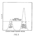
- Figure 3 for two exposure profiles deposited on a binary image-recording material by the same irradiance shape but produced by twice the power from the source on the left as on the right, the lateral extent of the exposure profile exceeding the density-change threshold is wider for greater source power.
- the local density at the center of the exposure profile deposited by the lower power is the same as the local density at the center of the exposure profile deposited by the higher power due to the binary response of the image-recording material.
- the density corresponding to the area-averaged transmittance or reflectance of an imaged area wider than the distance between successive pulsed exposures produced by the higher powered source differs from that produced by the lower powered source.
- the exposure profile deposited by a binary modulated irradiation source whose irradiance profile is scanned with respect to an image-recording medium behaves according to one of two regimes depending upon the relative duration of the pulse compared to the time for the center of the irradiation profile to traverse its full-width at half maximum on the image-recording medium: amplitude-modulated exposure comparable to contone imaging for shorter pulses, and binary modulated exposure of halftone imaging for longer pulses as compared to the irradiance-FWHM traversal time.
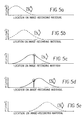
- Figures 4a-4e depict five instants during scanning of a binary-modulated irradiance profile past a location on the image-recording medium.
- the source is activated throughout all five instants, implying that the pulse is longer than the irradiance-FWHM traversal time.
- the first instant as depicted in Figure 4a and the last instant as depicted in Figure 4e deposit negligible amounts of the exposure accumulated at the location of the image-recording medium beneath the encircled point of the irradiance profile.
- Changing the power emitted by the source at any instant either before the first instant or after the last instant depicted in Figures 4a-4e would not substantially affect the exposure accumulated at the location on the image-recording medium beneath the encircled point.
- the insensitivity of this location to preceding or subsequent source power demonstrates the contention that pulse duration cannot exert significant control of the exposure amplitude for pulse-widths longer than the irradiance-FWHM traversal time.
- the pulse width in Figures 5a-5e are shorter than the irradiance-FWHM traversal time, lasting only from the instant depicted by Figure 5c to the instant of Figure 5d.
- the dotted irradiance profiles in of Figures 5a, 5b, and 5e show where the irradiance profile would have been projected onto the image-recording medium if the source were not extinguished by the pulse-width modulation. Changing the pulse duration would change the exposure deposited at the location beneath the encircled points.
- Control of the exposure amplitude exerted by pulse duration shorter than the irradiance-FWHM traversal time can be expressed quantitatively for the illustrative case of a radiation source emitting power P beam projected as an elliptical gaussian irradiance profile M [ x,y ] with standard-deviation radii ⁇ beam,x along the scanning direction x and ⁇ beam,y along direction y perpendicular both to the scan and to the propagation direction of the radiation:
- the error function is defined as:
- Pulse durations longer than the irradiance-FWHM traversal time can add no more than one-third of the exposure acquired up to this point, and those contributions come at the expense of accelerating length of pulses.
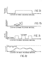
- Figure 7a depicts an exposure profile desired to be deposited on an image-recording medium along the scanning direction.
- Figure 7b captures a slice through the center of the irradiance profile of the exposing beam at one instant during its scan along the image-recording medium. This irradiance profile is scanned in the direction indicated by the hollow arrow containing V x . Its full-width at half maximum (FWHM) is delineated by the thick horizontal bar with vertical terminii.
- Figure 7c shows the pulse modulation sequence activating the beam at each of its binary levels in order to deposit an exposure profile reproducing the one in Figure 7a.
- This illustration of the pulse sequence specifically depicts on the vertical axis the power emitted by the source when the center of the irradiance profile is projected onto the location on the image-recording medium along the horizontal axis of Figure 7c.
- the temporal criterion of "a pulse duration shorter than the irradiance-FWHM traversal time” can be restated in terms of distances as "the distance scanned by an activated beam's center shorter than that beam's irradiance-profile FWHM".
- the duration of an individual "ON" pulse in Figure 7c is shorter than the FWHM bar in Figure 7b; also, the duration of each "OFF" pulse is shorter than the FWHM in order to satisfy the criterion for exposure control by pulse-width modulation.
- Figure 7d demonstrates that the exposure profile deposited by Figure 7b's irradiance profile pulse-width modulated in the contone regime according to Figure 7c and plotted as a thick solid curve can reproduce the desired exposure profile's amplitude and duration plotted as a dotted curve.
- the chain-dotted curve at the top of Figure 7d is the maximum exposure H [ t off -t on ⁇ ] as would be deposited by an infinitely long pulse applied to the same irradiance profile, beam power, and scan speed.
- the exposure profile deposited by the contone regime's short-pulse-modulated irradiance profile ripples modestly about the desired exposure profile but does not approach the upper limit of the infinitely long-pulsed exposure.
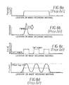
- Figures 8a-8d is the analog for the halftone regime of the contone regime in Figures 7a-7d.
- Figures 8a-8d employ a narrower beam along the scanning direction in Figure 8b so that than the distance scanned along the image-recording medium during the pulse-width duration schematized in Figure 8c is longer than the irradiance profile's full-width at half maximum.
- Attempting to reproduce the desired exposure profile of Figure 8a results in an exposure profile following the thick, solid curve in Figure 8c with some locations receiving the maximum possible exposure H [ t off -t on ⁇ ] separated by gaps of almost no exposure deposited on the image-recording medium.
- the actual exposure in the halftone regime rarely approximates the desired exposure at any location throughout the profile.
- the top track is produced by the preferred beam power, while the middle and bottom tracks are produced by beams with twice the preferred power.
- the beam is activated continuously during the scan length of the desired exposure in Figure 7a for both the top and bottom tracks, with the consequence that the bottom track written by the more powerful beam is wider in the direction perpendicular scanning than the preferred track width produced by the top, weaker beam.
- the middle track is modulated by the same pulse sequence as in Figure 7c, so the pulse-width modulation is operating in the contone regime in which the distance scanned by the beam center while activated by a pulse is shorter than the irradiance-profile FWHM, x .
- the middle track width produced by this modulated beam of twice the preferred power depicted as a solid thick curve, reproduces the smaller preferred track width, superimposed as a thin dashed curve. Ripples are evident in the modulated track about the preferred track in Figure 9a, but the modulated track width remains narrower than the track width of its unmodulated beam throughout the scan length.
- Figure 9b presents the halftone analog of Figure 9a.
- the irradiance profile is elliptical with shorter FWHM, x along the scanning direction than in Figure 9a but with the same FWHM, y as in Figure 9a perpendicular to the scanning direction.
- the irradiance profile along the scanning direction and consequent FWHM, x of the three beams in Figure 9b are the same as in Figure 8b.
- the middle and bottom beams emit twice the preferred power of the top beam.
- the top and bottom beams are unmodulated during the scan length of the desired exposure in Figure 8a, while the middle beam is modulated according to Figure 8c.
- the beam center scans farther than its FWHM, x during each modulating pulse, both "ON” and “OFF", so the modulation behaves according to the halftone regime.
- the middle track of the modulated beam is represented by the solid thick curves appearing as three ovals in Figure 9b.
- the track width of these ovals is wider than the width of the preferred track, superimposed as a dashed curve, and the ovals are separated by regions with inadequate exposure to attain the density-change threshold.
- the track width of the beam modulated by pulses longer than its FWHM traversal time remains almost unchanged from the upper limit of track width for the infinitely long pulse of the more powerful beam at the bottom of Figure 9b.
- those track widths can also be matched by modulating each beam by the appropriate pulses briefer than each FWHM, x traversal time.
- This method of adjusting track width can be especially beneficial for multiple light sources which cannot be amplitude modulated or which do not emit reproducible amounts of light when amplitude modulated.
- This method can also be useful with multiple sources that can only be addressed electronically by a binary signal, possibly due to space constraints, timing constraints, or expense of apparatus for implementing amplitude modulation.
Landscapes
- Engineering & Computer Science (AREA)
- Multimedia (AREA)
- Signal Processing (AREA)
- Physics & Mathematics (AREA)
- Optics & Photonics (AREA)
- Electronic Switches (AREA)
- Exposure And Positioning Against Photoresist Photosensitive Materials (AREA)
Abstract
Description
"the total optical energy applied to a picture element, i.e.,
the exposure H, is defined by the following expression:
In a further feature of the present invention, the amount of light deposited by each pixel at the media plane can be controlled, and therefore balanced, by adjusting the pulse width of the voltage applied to each individual pixel during a line printing time. There would need to be a calibration of the pixels before printing in order to determine the pulse width for each pixel. In this way, a more uniform printing by the entire array of pixels would result. This provides a means to correct for reasonable non-uniformities in the illuminations, the electrodes, the coatings and the crystal.
Its Claim 10 states:
A modulator according to claim 1, wherein a pulse width of a voltage applied to each pixel of said electrode is adjustable to balance light levels during printing.





Claims (10)
- A method of controlling exposure of a medium comprising the steps of:a) changing an emission level of a radiation source from a first power to a second power;b) emitting at said second power for less time than required by an irradiance profile to traverse a full-width at half maximum of said irradiance profile projected onto said medium along a direction of relative motion between said irradiance profile and said medium;c) changing said emission level to said first power;d) emitting at said first power for less time than required by said irradiance profile to traverse said full-width at half maximum of said irradiance profile projected onto said medium along said direction of relative motion between said irradiance profile and said medium; ande) changing said emission level to said second power.
- A method of controlling exposure of a medium as in claim 1 wherein a modulating signal generator changes said emission level.
- A method of controlling exposure of a medium as in claim 1 wherein a translation assembly moves said irradiance profile relative to said medium.
- A method of controlling exposure of a medium as in claim 1 wherein a translation assembly provides relative motion between said irradiance profile and said medium.
- A method of controlling exposure of a medium as in claim 1 wherein a translation assembly moves said medium along the direction of relative motion with respect to said irradiance profile.
- A method of controlling exposure of a medium as in claim 1 wherein an optical beam deflector moves said irradiance profile with respect to said medium.
- A method of controlling exposure of a medium as in claim 1 wherein said radiation source is a laser.
- A method of controlling exposure of a medium as in claim 1 wherein said radiation source is composed of a laser and a modulator.
- A method of controlling exposure of a medium as in claim 1 wherein said radiation source is composed of an emitter and a modulator.
- A method of controlling exposure of a medium as in claim 1 comprising the additional steps of:f) emitting at said second power for less time than required by said irradiance profile to traverse said full-width at half maximum of said irradiance profile projected onto said medium along said direction of relative motion between said irradiance profile and said medium; andg) changing said emission level to said first power.
Applications Claiming Priority (2)
| Application Number | Priority Date | Filing Date | Title |
|---|---|---|---|
| US810786 | 2001-03-16 | ||
| US09/810,786 US6590600B2 (en) | 2001-03-16 | 2001-03-16 | Method and apparatus for controlling exposure amplitude and printed track width by pulse width modulation |
Publications (2)
| Publication Number | Publication Date |
|---|---|
| EP1241867A2 true EP1241867A2 (en) | 2002-09-18 |
| EP1241867A3 EP1241867A3 (en) | 2005-02-02 |
Family
ID=25204699
Family Applications (1)
| Application Number | Title | Priority Date | Filing Date |
|---|---|---|---|
| EP02075875A Withdrawn EP1241867A3 (en) | 2001-03-16 | 2002-03-04 | A method and apparatus for controlling exposure amplitude and printed track width by pulse width modulation |
Country Status (2)
| Country | Link |
|---|---|
| US (1) | US6590600B2 (en) |
| EP (1) | EP1241867A3 (en) |
Families Citing this family (6)
| Publication number | Priority date | Publication date | Assignee | Title |
|---|---|---|---|---|
| WO2008144443A1 (en) | 2007-05-18 | 2008-11-27 | Gsi Group Corporation | Laser processing of conductive links |
| WO2010083877A1 (en) * | 2009-01-24 | 2010-07-29 | Ebm-Papst St. Georgen Gmbh & Co. Kg | Electric motor and device for generating a signal for controlling the same |
| US12566397B2 (en) | 2021-10-21 | 2026-03-03 | Viavi Solutions Inc. | Electrostatic printing method |
| US12083813B2 (en) | 2021-10-21 | 2024-09-10 | Viavi Solutions Inc. | Printing machine and fixed patterned plate |
| US20230128872A1 (en) * | 2021-10-21 | 2023-04-27 | Viavi Solutions Inc. | A fixed color image including pixels and method of making the color image |
| EP4429896A4 (en) | 2021-11-12 | 2025-08-06 | Viavi Solutions Inc | ARTICLES CONTAINING AN IMAGE WITH TWO OR MORE TYPES OF PIXELS |
Family Cites Families (15)
| Publication number | Priority date | Publication date | Assignee | Title |
|---|---|---|---|---|
| JPS56152372A (en) | 1980-04-24 | 1981-11-25 | Fuji Photo Film Co Ltd | Laser recording device |
| JPS56153331A (en) * | 1980-04-30 | 1981-11-27 | Fuji Photo Film Co Ltd | Laser recorder |
| US4455578A (en) * | 1982-08-30 | 1984-06-19 | Eastman Kodak Company | Electronics for arrayed photosources |
| JPS6374664A (en) * | 1986-09-18 | 1988-04-05 | Sony Corp | Drive circuit of thermal head |
| DE68916562T2 (en) * | 1988-03-10 | 1994-11-24 | Canon Kk | Imaging processes. |
| US5291221A (en) | 1991-08-23 | 1994-03-01 | Eastman Kodak Company | Method and apparatus for the calibration of a multichannel printer |
| US5323179A (en) | 1991-08-23 | 1994-06-21 | Eastman Kodak Company | Method of calibrating a multichannel printer |
| US5266973A (en) | 1991-08-23 | 1993-11-30 | Eastman Kodak Company | Methods for measuring laser performance in laser printers |
| US5619488A (en) * | 1991-09-07 | 1997-04-08 | Fuji Xerox Co., Ltd. | Information recording device |
| US5241328A (en) | 1991-09-20 | 1993-08-31 | Eastman Kodak Company | Apparatus and method for thermal printing of finely detailed images of photographic quality |
| US5216443A (en) * | 1992-06-12 | 1993-06-01 | Xerox Corporation | Programmable intensity smart laser system capable of being fabricated on a semiconductive substrate |
| US5874981A (en) | 1995-09-19 | 1999-02-23 | Eastman Kodak Company | Combined pulse-width and amplitude modulation of exposing laser beam for thermal dye transfer |
| US6011575A (en) * | 1996-09-10 | 2000-01-04 | Konica Corporation | Image forming apparatus with line-shaped image exposure means |
| US6060208A (en) | 1996-12-16 | 2000-05-09 | Creo Products Inc. | Method for matching optical density in color proofing |
| JP2000123367A (en) * | 1998-10-14 | 2000-04-28 | Toshiba Corp | Recording method and recording apparatus for phase change optical recording medium |
-
2001
- 2001-03-16 US US09/810,786 patent/US6590600B2/en not_active Expired - Lifetime
-
2002
- 2002-03-04 EP EP02075875A patent/EP1241867A3/en not_active Withdrawn
Also Published As
| Publication number | Publication date |
|---|---|
| US6590600B2 (en) | 2003-07-08 |
| US20020191070A1 (en) | 2002-12-19 |
| EP1241867A3 (en) | 2005-02-02 |
Similar Documents
| Publication | Publication Date | Title |
|---|---|---|
| JP2930717B2 (en) | Thermal printer | |
| JP2933715B2 (en) | Thermal printer | |
| EP0526000B1 (en) | Microaddressability via overscanned illumination for optical printers and the like having high gamma photosensitive recording media | |
| US7231096B2 (en) | Screening method for overlapping sub-images | |
| KR19990014017A (en) | Inkjet Printing Device and Method | |
| US8733921B2 (en) | Method of ink jet printing with image quality control | |
| JP2524108B2 (en) | Optical scanning recorder | |
| JPH09504747A (en) | Optical data recording | |
| JP3328906B2 (en) | Apparatus and method for thermal printing of high definition images of photographic quality | |
| US6060208A (en) | Method for matching optical density in color proofing | |
| US5233366A (en) | Half-tone printing with thermal ink jet using random spot distribution in one dimension | |
| US6590600B2 (en) | Method and apparatus for controlling exposure amplitude and printed track width by pulse width modulation | |
| US6618158B1 (en) | Method and device for calibrating an imaging apparatus having multiple imaging outputs | |
| GB2372898A (en) | Printer that scales print resolution according to print speed | |
| US6587221B1 (en) | Scanning device and method | |
| EP0565460A2 (en) | Improved thermal printing system | |
| JPH01257868A (en) | Information printing device | |
| US6181356B1 (en) | Pattern image reader device and image stabilizer device incorporated in image forming apparatus | |
| JPH0524219A (en) | Optical beam recording method on thermal recording material and apparatus thereof | |
| EP0676714B1 (en) | Exposure controlling method and apparatus in a laser printer | |
| US5212569A (en) | Light beam scanning apparatus capable of changing the scanning density | |
| US5874981A (en) | Combined pulse-width and amplitude modulation of exposing laser beam for thermal dye transfer | |
| US6169563B1 (en) | Image recording apparatus having a plurality of laser diodes | |
| EP1136272B1 (en) | Apparatus for and method of recording image | |
| EP1213682A2 (en) | Print image enhancement in LED array xerographic printing |
Legal Events
| Date | Code | Title | Description |
|---|---|---|---|
| PUAI | Public reference made under article 153(3) epc to a published international application that has entered the european phase |
Free format text: ORIGINAL CODE: 0009012 |
|
| AK | Designated contracting states |
Kind code of ref document: A2 Designated state(s): AT BE CH CY DE DK ES FI FR GB GR IE IT LI LU MC NL PT SE TR |
|
| AX | Request for extension of the european patent |
Free format text: AL;LT;LV;MK;RO;SI |
|
| PUAL | Search report despatched |
Free format text: ORIGINAL CODE: 0009013 |
|
| AK | Designated contracting states |
Kind code of ref document: A3 Designated state(s): AT BE CH CY DE DK ES FI FR GB GR IE IT LI LU MC NL PT SE TR |
|
| AX | Request for extension of the european patent |
Extension state: AL LT LV MK RO SI |
|
| RIC1 | Information provided on ipc code assigned before grant |
Ipc: 7H 04N 1/405 B Ipc: 7H 04N 1/40 A |
|
| 17P | Request for examination filed |
Effective date: 20050708 |
|
| AKX | Designation fees paid |
Designated state(s): DE FR GB |
|
| STAA | Information on the status of an ep patent application or granted ep patent |
Free format text: STATUS: THE APPLICATION HAS BEEN WITHDRAWN |
|
| 18W | Application withdrawn |
Effective date: 20051125 |