EP1241816A2 - Receiver having retransmission function - Google Patents
Receiver having retransmission function Download PDFInfo
- Publication number
- EP1241816A2 EP1241816A2 EP02005677A EP02005677A EP1241816A2 EP 1241816 A2 EP1241816 A2 EP 1241816A2 EP 02005677 A EP02005677 A EP 02005677A EP 02005677 A EP02005677 A EP 02005677A EP 1241816 A2 EP1241816 A2 EP 1241816A2
- Authority
- EP
- European Patent Office
- Prior art keywords
- radio wave
- audio signal
- receiving situation
- modulation processing
- modulation
- Prior art date
- Legal status (The legal status is an assumption and is not a legal conclusion. Google has not performed a legal analysis and makes no representation as to the accuracy of the status listed.)
- Withdrawn
Links
Images



Classifications
-
- H—ELECTRICITY
- H04—ELECTRIC COMMUNICATION TECHNIQUE
- H04H—BROADCAST COMMUNICATION
- H04H20/00—Arrangements for broadcast or for distribution combined with broadcast
- H04H20/02—Arrangements for relaying broadcast information
- H04H20/08—Arrangements for relaying broadcast information among terminal devices
-
- H—ELECTRICITY
- H04—ELECTRIC COMMUNICATION TECHNIQUE
- H04B—TRANSMISSION
- H04B1/00—Details of transmission systems, not covered by a single one of groups H04B3/00 - H04B13/00; Details of transmission systems not characterised by the medium used for transmission
- H04B1/06—Receivers
- H04B1/16—Circuits
- H04B1/1646—Circuits adapted for the reception of stereophonic signals
-
- H—ELECTRICITY
- H04—ELECTRIC COMMUNICATION TECHNIQUE
- H04H—BROADCAST COMMUNICATION
- H04H40/00—Arrangements specially adapted for receiving broadcast information
- H04H40/18—Arrangements characterised by circuits or components specially adapted for receiving
- H04H40/27—Arrangements characterised by circuits or components specially adapted for receiving specially adapted for broadcast systems covered by groups H04H20/53 - H04H20/95
- H04H40/36—Arrangements characterised by circuits or components specially adapted for receiving specially adapted for broadcast systems covered by groups H04H20/53 - H04H20/95 specially adapted for stereophonic broadcast receiving
- H04H40/45—Arrangements characterised by circuits or components specially adapted for receiving specially adapted for broadcast systems covered by groups H04H20/53 - H04H20/95 specially adapted for stereophonic broadcast receiving for FM stereophonic broadcast systems receiving
- H04H40/81—Arrangements characterised by circuits or components specially adapted for receiving specially adapted for broadcast systems covered by groups H04H20/53 - H04H20/95 specially adapted for stereophonic broadcast receiving for FM stereophonic broadcast systems receiving for stereo-monaural switching
Definitions
- the present invention relates to a receiver which receives a broadcast radio wave, performs a variety of modulation processing on an audio signal included in the broadcast radio wave, and retransmits the audio signal on a radio wave different from the received radio wave.
- some conventionally known receivers for television broadcasting and satellite broadcasting have a function of extracting only an audio signal from received and reproduced information signals, frequency modulating (FM) the audio signal, and retransmitting the frequency modulated audio signal as a weak radio wave (see Laid-open Japanese Patent Applications Nos. 6-268936, 11-331000).
- These receivers having a retransmission function generally set the frequency of a FM radio wave to be retransmitted within the frequency band of the FM broadcasting (76 - 90 MHz) in Japan. Therefore, a receiver having such a function permits the user to hear only an audio signal extracted from the television broadcasting and satellite broadcasting, using an ordinary FM radio.
- a deteriorated receiving situation results in a gradual increase in noise in an audio signal included in a retransmitted FM radio wave.
- noise will not increase even if the receiving situation deteriorates to some degree.
- the reception quality suddenly degrades. This results in a sudden increase in noise in an audio signal included in a retransmitted FM radio wave.
- the present invention provides a receiver with a retransmission function which has a receiving/reproducing part for receiving a broadcast radio wave and reproducing an audio signal included in the broadcast radio wave, a receiving situation determining part for determining a receiving situation of the broadcast radio wave, and a modulating/transmitting part for performing predetermined modulation processing on the audio signal, and retransmitting the processed audio signal on a broadcast radio wave different from the received broadcast radio wave, wherein the modulating/transmitting part performs a variety of modulation processing in accordance with a determination result in the receiving situation determining part.
- Fig. 1 is a block diagram illustrating the configuration of a digital broadcast receiver having a retransmission function according to an embodiment of the present invention
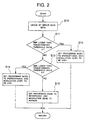
- Fig. 2 is a flow chart illustrating the operation for controlling modulation processing in a retransmitting section in the embodiment illustrated in Fig. 1;
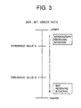
- Fig. 3 is an explanatory diagram showing the relationship between a bit error rate and a receiving situation and a predetermined threshold value
- Fig. 4 is an explanatory diagram showing the relationship between a modulation frequency and a resulting noise voltage in the FM modulation processing.
- Fig. 5 is an explanatory diagram showing the relationship between a stereo/monophonic modulation processing mode and a noise voltage in the frequency modulation.
- Fig. 1 is a block diagram illustrating the configuration of a digital broadcast receiver according to an embodiment of the present invention.
- a digital broadcast reception antenna 10 is an antenna for receiving digital broadcasting radio waves, for example, satellite waves and terrestrial waves.
- An analog demodulator unit 11 is a so-called radio frequency (RF) processing unit comprised of a frequency converter circuit, a tuning circuit, a detector/demodulator circuit, and the like.
- a digital demodulator unit 12 which is comprised of a variety of digital decoding circuits, an error correcting circuit and the like, is a unit responsible for demodulation and reproduction processing of a digital signal.
- a digital/analog converter unit (hereinafter called the D/A converter unit) 13 is a circuit for converting an audio signal and a video signal included in a reproduced digital signal to analog signals.
- the foregoing units constitute a digital broadcast receiving section in this embodiment.
- a control unit 14 is mainly comprised of a microcomputer and a memory circuit.
- the memory circuit is comprised of memory devices such as a ROM (Read Only Memory), a RAM (Random Access Memory) and the like.
- the microcomputer in the control unit 14 executes a predetermined control program stored in the ROM, based on an internal clock signal. Then, the control unit 14 governs the control of the overall digital broadcast receiver illustrated in Fig. 1. Specifically, the control unit 14 controls the respective units of the aforementioned digital broadcast receiving section. Simultaneously, the control unit 14 receives the supply of text data (received character information), which is demodulated and reproduced from the receiving section, and a variety of data indicative of a receiving situation. Then, the control unit 14 executes a variety of processing required by the digital broadcast receiver.
- text data received character information
- An information output unit 15 governs conversion processing for data formats and signal forms for an audio signal, a video signal, a text (character) signal and the like reproduced from a received digital broadcast radio wave.
- the converted signal is output to an external device, for example, speakers, a large sized display and the like, external to the digital broadcast receiver.
- a manipulation/display unit 20 is comprised of a manipulation/display panel and an interface circuit. Then, the manipulation/display panel comprises a manipulation unit comprised of a variety of push buttons, numeral keys and the like, and a display unit comprised of a variety of LEDs, a liquid crystal display, and the like.
- the user can control the receiver through the manipulation/display unit 20.
- the user can also monitor the state of the receiver, and received information on texts (characters), video and the like through the manipulation/display unit 20.
- An FM carrier oscillator unit 16 is a unit for generating a carrier for retransmitting an audio signal extracted from the received digital broadcast radio wave as an FM radio wave.
- the FM carrier oscillator unit 16 may be comprised of a highly accurate oscillator circuit which uses a piezoelectric resonance element, for example, a quartz element, a ceramic element, or the like.
- a frequency modulation unit 17 performs stereophonic modulation processing or monophonic modulation processing on an audio signal output from the D/A converter unit 13. Subsequently, the frequency modulation unit 17 uses this processed signal as a modulating signal to frequency modulate the carrier from the FM carrier oscillator unit 16.
- a modulation factor during frequency modulation is controlled by a modulation level control signal supplied from the control unit 14.
- switching to the stereophonic modulation processing or monophonic modulation processing is controlled by a stereophonic/monophonic switching signal (hereinafter called a ST/MO switching signal) supplied from the control unit 14.
- ST/MO switching signal a stereophonic/monophonic switching signal supplied from the control unit 14.
- a retransmission amplifying unit 18 is a unit for performing high frequency output processing on an output signal from the frequency modulation unit 17.
- high frequency output processing refers to processing such as frequency multiplication, high frequency amplification and the like.
- the foregoing FM carrier oscillator unit 16, frequency modulation unit 17 and retransmission amplifying unit 18 constitute an FM retransmitting section in this embodiment.
- a retransmission antenna 19 is an antenna for radiating an FM radio wave output from the aforementioned FM retransmitting section.
- the FM radio wave retransmitted in this embodiment is a weak radio wave which does not require a license.
- a car-equipped FM receiver for receiving this radio wave is also located quite near the receiver according to this embodiment. For this reason, the retransmission antenna 19 may be omitted.
- a car-equipped FM receiver 21 is also required as a device for receiving a retransmitted FM radio wave.
- a receiver may be any one that can receive stereo broadcasting in an FM broadcasting band (76 - 90 MHz) in Japan. Since such a receiver can be generally implemented by widely used devices such as a car radio, car stereo tuner or the like, description thereof is omitted.
- a digital broadcast radio wave received by the digital broadcast reception antenna 10 is detected and demodulated in the analog demodulator unit 11, and supplied to the digital demodulator unit 12.
- the digital demodulator unit 12 demodulates an analog output from the analog demodulator unit 11 to a digital signal. Then, the demodulated signal undergoes reproduction processing such as deinterleaving, which is a rearrangement of a digital signal sequence, error detection, error correction and the like. Out of the reproduced digital signals, text(character) data, and code data associated therewith are output from the digital broadcast receiving section to the control unit 14 together with other information indicative of a variety of receiving situations.
- the digital demodulator unit 12 outputs the reproduced digital signal to the D/A converter unit 13.
- the D/A converter unit 13 converts this digital signal to an analog signal.
- an analog signal includes an audio signal and a video signal.
- the audio signal is output to the frequency modulation unit 17 and information output unit 15.
- the video signal in turn is output to the information output unit 15 and manipulation/display unit 20.
- an audio signal is typically transmitted in stereophony in the digital broadcasting. Therefore, the audio signal is reproduced as an Right-channel signal and a Left-channel signal (hereinafter called an R-ch signal and a L-ch signal) of stereophony, and output from the D/A converter unit 13 to the FM retransmitting section.
- an R-ch signal and a L-ch signal Right-channel signal and a Left-channel signal
- the R-ch and L-ch signals from the D/A converter unit 13 are input to the frequency modulation unit 17 in the FM retransmitting section.
- the frequency modulation unit 17 is comprised of a part responsible for the stereophonic modulation processing, and a part responsible for the frequency modulation processing.
- the former includes an R/L matrix circuit required from the stereophonic transmission, and an oscillator circuit for oscillating a main carrier and a sub-carrier of the stereophonic signal.
- the latter includes a frequency modulation circuit for modulating the carrier using a modulating signal which has undergone the stereophonic modulation processing.
- the frequency modulation unit 17 performs the stereophonic modulation processing using the R-ch and L-ch audio signals.
- the frequency modulation unit 17 may performs the monophonic modulation processing, as well as the stereophonic modulation processing, depending on a receiving situation of digital broadcasting.
- the monophonic modulation processing refers to processing for generating a main channel signal for stereophonic transmission comprised of the sum of the R-ch and L-ch audio signals.
- Whether the frequency modulation unit 17 selects the stereophonic or monophonic modulation processing mode is determined by the ST/MO switching signal supplied from the control unit 14.
- the frequency modulation unit 17 performs frequency modulation on the carrier supplied from the FM carrier oscillator unit 16, using the modulating signal which has undergone the stereophonic modulation processing or monophonic modulation processing.
- the foregoing modulating signal may be applied to a gate of a reactance varying element in a circuit which is supplied with the carrier.
- a variable capacitance diode may be connected in parallel with a carrier tuning circuit to superpose the modulating signal on a direct current bias voltage of the diode.
- a level of the modulation factor in the frequency modulation processing, i.e., the magnitude of the modulation level is controlled by a modulation level control signal supplied from the control unit 14.
- the ST/MO switching signal and modulation level control signal are generated by the control unit 14 based on the received signal quality acquired from the digital demodulator unit 12.
- the retransmission amplifying unit 18 is a high frequency amplifying unit comprised of a frequency multiplier circuit, a buffer amplifier circuit, and the like.
- a modulated carrier signal output from the frequency modulation unit 17 is multiplied to have a predetermined frequency in the retransmission amplifying unit 18.
- the modulated carrier signal is amplified to a proper signal level, and then radiated from the retransmission antenna 19.
- the retransmitted FM radio wave is a so-called weak radio wave which has an extremely low signal level. Therefore, the retransmission amplifying unit 18 may be omitted by previously setting the oscillating frequency of the FM carrier oscillator unit 16 to a value within the FM broadcasting band (76 -90 MHz) in Japan.
- the microcomputer within the control unit 14 executes at all times a main routine program (not shown) for controlling the operation of the overall digital broadcast receiver illustrated in Fig. 1. Meanwhile, the microcomputer repeatedly executes a subroutine program illustrated in Fig. 2 as appropriate.
- the subroutine in Fig. 2 illustrates the control operation for the modulation processing in the FM retransmitting section in Fig. 1.
- This subroutine may be periodically initiated by a built-in timer of the microcomputer. Alternatively, the subroutine may be initiated each time the control unit 14 receives received reproduced data and receiving situation data associated therewith from the digital broadcast receiving section.
- the microcomputer (hereinafter simply called the ⁇ CPU) of the control unit 14 first obtains a bit error rate (hereinafter simply called the BER) from the receiving situation data received from the digital broadcast receiving section (step 10).
- the ⁇ CPU compares the obtained value of BER with a predetermined threshold value A previously stored in the memory of the control unit 14 at next step 11.
- the relationship between the predetermined threshold value A and BER is as shown in Fig. 3. Specifically, the value of BER is smaller as the receiving situation inproves. Then, the receiving situation deteriorates as the value of BER gradually increases. In Fig. 3, the receiving situation is quite satisfactory if BER is lower than the threshold value A. On the other hand, when BER is equal to greater than a threshold value B, this indicates that the receiving situation is extremely bad or the digital broadcasting cannot be received.
- the ⁇ CPU proceeds to step 12. Then, the ⁇ CPU sets the modulation processing mode of the frequency modulation unit 17 in the FM retransmitting section to the stereophonic modulation processing. Further, the ⁇ CPU sets the modulation level during the frequency modulation to be high in the modulator unit 17.
- the modulation level used herein refers to an index indicative of the magnitude of a frequency deviation of a modulating signal during the frequency modulation of the frequency modulation unit 17. Specifically, a higher modulation level means a wider frequency band of the modulating signal. On the other hand, a lower modulation level means a narrower frequency band of the modulating signal.
- control unit 14 outputs the ST/MO switching signal instructing the stereophonic modulation processing, and the modulation level control signal instructing a high modulation level to the frequency modulation unit 17 based on the settings at step 12.
- the triangular noise characteristic refers to a noise voltage in an FM radio wave which increases in proportion to the frequency of a modulating signal.
- a main channel (L-ch + R-ch) signal maximally having a band of 15 kHz may be used for the modulating signal for the frequency modulation.
- a sub-channel (L-ch - R-ch) must be transmitted in addition to the main channel signal. Then, the sub-channel signal requires double sideband waves of maximally having a band of 23 - 53 kHz, about the stereophonic subcarrier(38 kHz).
- the frequency band of the modulating signal extends 53 kHz at maximum, which is the sum of the (L-ch + R-ch) signal and (L-ch - R-ch) signal. This is because the stereophonic modulation processing results in increased triangular noise as compared with the monophonic modulation processing, as shown in Fig. 5.
- a value of BER lower than the threshold value A indicates that the receiving situation of the digital broadcasting is quite satisfactory.
- the audio signal extracted from the received radio wave of the digital broadcasting also has a satisfactory signal quality. Therefore, with such an audio signal of high quality, even if the modulation level is set to be high and the stereophonic modulation processing is performed in the frequency modulation unit 17, a resulting increase in the noise level can be ignored. In other words, when the receiving situation is satisfactory, the degraded S/N ratio will not cause any problem in the FM retransmitted signal even if the stereophonic modulation processing is performed with a high modulation level.
- a listener can enjoy an audio signal extracted from the digital broadcasting as broadband stereophony broadcasting, using an FM radio.
- the ⁇ CPU in the control unit 14 terminates the subroutine of Fig.2 and returns to the main routine when the settings at step 12 are completed.
- the ⁇ CPU determines whether or not BER is lower than the predetermined threshold value B (step 13). Then, if BER is lower than the predetermined threshold value B, i.e., the value of BER satisfies A ⁇ BER ⁇ B, the ⁇ CPU proceeds to step 14.
- the receiving situation in the digital broadcast receiving section is not so satisfactory as that which was found at the aforementioned step 12, as is also apparent from Fig. 3.
- the receiving situation in the digital broadcast receiving section ensures a predetermined level. It is therefore contemplated that the signal quality of the audio signal extracted from the received radio wave still maintains a predetermined level even though the noise has increased to some degree.
- the ⁇ CPU maintains the modulation processing mode in the frequency modulation unit 17 set to the stereophonic modulation processing, and sets the modulation level of the frequency modulation to be low.
- the modulation processing mode in the FM radio wave for retransmitting the audio signal extracted from the received digital broadcasting, the form of transmitting the signal in stereophony is maintained.
- the band of the modulating signal frequency is narrowed during the frequency modulation. This can reduce the triangular noise associated with the frequency modulation.
- this can alleviate a degraded S/N ratio of the FM retransmitted signal due to the degraded quality of the received signal.
- control unit 14 Based on the settings at step 14, the control unit 14 outputs the ST/MO switching signal which instructs the stereophonic modulation processing, and the modulation level control signal which instructs a low modulation level to the frequency modulation unit 17.
- the ⁇ CPU terminates the subroutine of Fig. 2 and once returns to the main routine when the settings at step 14 are completed.
- the ⁇ CPU proceeds to step 15. Then, the ⁇ CPU sets the modulation processing mode in the frequency modulation unit 17 to the monophonic modulation processing, and sets the modulation level during the frequency modulation to a minimum. In this event, it is contemplated that the receiving situation of the digital broadcast radio wave has extremely deteriorated, so that the signal quality of the audio signal extracted from a received radio wave is extremely degraded as well, and many noise components are included.
- the degraded S/N ratio can be maximally alleviated when a low quality audio signal is retransmitted as the FM radio wave.
- the subroutine in Fig. 2 executes the processing at step 15 in the flow chart.
- the retransmitted FM radio wave includes no audio signal, i.e., is mute. Since the monophonic modulation processing causes less noise, as compared with the stereophonic modulation processing, the noise can be limited in a muted FM radio.
- the ⁇ CPU terminates the subroutine in Fig. 2 when the settings at step 15 are completed.
- the digital broadcasting is characterized in that noise suddenly increases when the error rate exceeds a predetermined value, from a relationship of the error correction processing. According to this embodiment, such noise can be reduced in the audio signal retransmitted through the FM radio wave. Also, spike noise caused by unlocking inherent in the digital broadcasting can also be reduced in a similar manner.
- the two threshold values A, B are provided for BER in the control of the modulation level
- the present invention is not limited to this.
- the number of set thresholds may be increased such that the value of modulation level is more finely adjusted in accordance with a varying receiving situation.
- the control unit 14 may acquire a received field strength, or a value of C/N ratio in the received radio wave, which can be detected by the analog demodulator unit 11, to switch the modulation level and modulation processing in the frequency modulation unit 17 using such a value as a determination criterion.
- the received field strength and the C/N ratio in the received radio wave may be used in combination with the aforementioned BER as determination criteria.
- the degraded S/N ratio in the radio wave signal during retransmission can be improved even if a receiving situation of the received radio wave deteriorates to cause a lower S/N ratio of the audio signal.
Landscapes
- Engineering & Computer Science (AREA)
- Signal Processing (AREA)
- Computer Networks & Wireless Communication (AREA)
- Stereo-Broadcasting Methods (AREA)
- Circuits Of Receivers In General (AREA)
- Superheterodyne Receivers (AREA)
Abstract
Simultaneously, depending on the varying receiving situation, the processing performed on the audio signal is switched to monophonic or stereophonic.
Description
Specifically, the
Claims (5)
- A receiver comprising:wherein said predetermined modulation processing is performed in accordance with a determination result in said receiving situation determining part.a receiving/reproducing part for receiving a broadcast radio wave and reproducing an audio signal included in said broadcast radio wave;a receiving situation determining part for determining a receiving situation of said broadcast radio wave; anda modulating/transmitting part for performing predetermined modulation processing on said audio signal, and transmitting a different broadcast radio wave, which includes the processed audio signal, from said broadcast radio wave,
- A receiver according to claim 1, wherein said
modulating/transmitting part performs frequency modulation processing on said audio signal, transmits the different broadcast radio wave including the modulated audio signal, and adjusts a modulation level in said frequency modulation processing in accordance with the determination result in said receiving situation determining part. - A receiver according to claim 2, wherein said
modulating/transmitting part reduces a value of the modulation level in said frequency modulation processing from a value of when the receiving situation is satisfactory, if said receiving situation determining part determines that the receiving situation deteriorates. - A receiver according to claim 1, wherein said
modulating/transmitting part performs frequency modulation, which includes stereophonic modulation processing, on said audio signal in said predetermined modulation processing when the receiving situation is satisfactory in accordance with the determination result in said receiving situation determining part, and transmits the different broadcast radio wave including the modulated audio signal, whereas modulating/transmitting part performs frequency modulation, which includes monophonic modulation processing, on said audio signal in said predetermined modulation processing when the receiving situation deteriorates in accordance with the determination result in said receiving situation determining part, and transmits the different broadcast radio wave including the modulated audio signal - A receiver according to claim 1, wherein said
modulating/transmitting part performs frequency modulation processing on said audio signal, conducts at least one of a control for minimizing a modulation level in said frequency modulation processing, and a control for performing monophonic modulation processing on said audio signal, and transmits the different broadcast radio wave including the modulated audio signal, when said receiving situation determining part determines that the receiving situation significantly deteriorates.
Applications Claiming Priority (2)
| Application Number | Priority Date | Filing Date | Title |
|---|---|---|---|
| JP2001070057A JP2002271222A (en) | 2001-03-13 | 2001-03-13 | Receiver with retransmission function |
| JP2001070057 | 2001-03-13 |
Publications (2)
| Publication Number | Publication Date |
|---|---|
| EP1241816A2 true EP1241816A2 (en) | 2002-09-18 |
| EP1241816A3 EP1241816A3 (en) | 2003-11-26 |
Family
ID=18927993
Family Applications (1)
| Application Number | Title | Priority Date | Filing Date |
|---|---|---|---|
| EP02005677A Withdrawn EP1241816A3 (en) | 2001-03-13 | 2002-03-12 | Receiver having retransmission function |
Country Status (3)
| Country | Link |
|---|---|
| US (1) | US6950626B2 (en) |
| EP (1) | EP1241816A3 (en) |
| JP (1) | JP2002271222A (en) |
Cited By (1)
| Publication number | Priority date | Publication date | Assignee | Title |
|---|---|---|---|---|
| DE102005014199A1 (en) * | 2005-03-29 | 2006-10-05 | Hirschmann Electronics Gmbh | Signals e.g. television and/or radio signals, receiving arrangement, has signal processing unit that decodes received signals and converts decoded signals to analog signals, which are guided to output of head end |
Families Citing this family (11)
| Publication number | Priority date | Publication date | Assignee | Title |
|---|---|---|---|---|
| JP3691365B2 (en) * | 2000-08-23 | 2005-09-07 | 三洋電機株式会社 | Digital broadcast receiver |
| FR2841709A1 (en) * | 2002-06-28 | 2004-01-02 | Koninkl Philips Electronics Nv | RECEIVER WITH AUTOMATIC FREQUENCY CONTROL |
| JP4232026B2 (en) * | 2004-02-27 | 2009-03-04 | ミツミ電機株式会社 | Composite antenna device and moving body including the same |
| US20060160486A1 (en) * | 2005-01-14 | 2006-07-20 | Xm Satellite Radio, Inc. | Method and system for converting streaming digital data to FM modulated data |
| AU2006200038A1 (en) * | 2005-03-09 | 2006-09-28 | Nec Australia Pty Ltd | Measuring received signal quality |
| JP4622598B2 (en) * | 2005-03-15 | 2011-02-02 | カシオ計算機株式会社 | Receiver circuit |
| US8010370B2 (en) * | 2006-07-28 | 2011-08-30 | Apple Inc. | Bitrate control for perceptual coding |
| US8032371B2 (en) * | 2006-07-28 | 2011-10-04 | Apple Inc. | Determining scale factor values in encoding audio data with AAC |
| WO2010033779A1 (en) * | 2008-09-19 | 2010-03-25 | Delphi Technologies, Inc. | A multi-beam, polarization diversity narrow-band cognitive antenna |
| US8090318B2 (en) * | 2009-02-24 | 2012-01-03 | Semiconductor Components Industries, Llc | Digital data processing circuit |
| US8081927B2 (en) * | 2009-02-25 | 2011-12-20 | Semiconductor Components Industries, Llc | Digital data processing circuit |
Family Cites Families (10)
| Publication number | Priority date | Publication date | Assignee | Title |
|---|---|---|---|---|
| JPS6122366Y2 (en) * | 1978-07-28 | 1986-07-04 | ||
| US5119503A (en) * | 1991-02-19 | 1992-06-02 | Mankovitz Roy J | Apparatus and methods for broadcasting auxiliary data in an FM stereo broadcast system |
| JPH06268936A (en) | 1993-03-16 | 1994-09-22 | Sharp Corp | Television receiver with built-in satellite broadcast receiving function |
| DE19542738A1 (en) * | 1995-11-16 | 1997-05-22 | Bayerische Motoren Werke Ag | Switching arrangement for mobile radio receivers |
| US5777997A (en) * | 1996-03-07 | 1998-07-07 | Hughes Electronics Corporation | Method and system for transmitting audio-associated text information in a multiplexed transmission stream |
| JPH10145253A (en) * | 1996-11-14 | 1998-05-29 | Alpine Electron Inc | Fm modulator |
| US6023616A (en) * | 1998-03-10 | 2000-02-08 | Cd Radio Inc. | Satellite broadcast receiver system |
| DK2278744T3 (en) * | 1997-10-14 | 2013-10-28 | Wi Lan Inc | Method and apparatus for maintaining a predefined transmission quality in a wireless MAN network |
| JPH11331000A (en) * | 1998-05-15 | 1999-11-30 | Mitsubishi Electric Corp | FM broadcast receiving apparatus and FM multiplex receiving apparatus |
| US6272328B1 (en) * | 1999-05-12 | 2001-08-07 | Xm Satellite Radio Inc. | System for providing audio signals from an auxiliary audio source to a radio receiver via a DC power line |
-
2001
- 2001-03-13 JP JP2001070057A patent/JP2002271222A/en not_active Abandoned
-
2002
- 2002-03-12 EP EP02005677A patent/EP1241816A3/en not_active Withdrawn
- 2002-03-12 US US10/095,120 patent/US6950626B2/en not_active Expired - Fee Related
Cited By (1)
| Publication number | Priority date | Publication date | Assignee | Title |
|---|---|---|---|---|
| DE102005014199A1 (en) * | 2005-03-29 | 2006-10-05 | Hirschmann Electronics Gmbh | Signals e.g. television and/or radio signals, receiving arrangement, has signal processing unit that decodes received signals and converts decoded signals to analog signals, which are guided to output of head end |
Also Published As
| Publication number | Publication date |
|---|---|
| US6950626B2 (en) | 2005-09-27 |
| US20020146984A1 (en) | 2002-10-10 |
| JP2002271222A (en) | 2002-09-20 |
| EP1241816A3 (en) | 2003-11-26 |
Similar Documents
| Publication | Publication Date | Title |
|---|---|---|
| US20020058475A1 (en) | System for providing signals from an auxiliary audio source to a radio receiver using a wireless link | |
| US6950626B2 (en) | Receiver having retransmission function | |
| CN103404039B (en) | Reserve frequency in radio switches, the method for automatic search and automatic tuning to one frequency | |
| KR100248916B1 (en) | Audio level equalization sound, brocadcast fm and national weather service fm radio signals | |
| US20050003772A1 (en) | IBOC broadcast receiver | |
| US20030026364A1 (en) | Broadcast receiver having automatic gain control function | |
| US4455573A (en) | Television sound receiver | |
| KR100210312B1 (en) | Audio level equalization of broadcast fm and national weather service fm radio signals | |
| US5113446A (en) | Stereo blend controller for FM receivers | |
| KR100211620B1 (en) | First IF filter with fixed second half-IF trap used for FM radio in television receiver | |
| JP2001217735A (en) | Broadcasting receiver | |
| KR100211411B1 (en) | TV system for receiving FM information radio by synthesis of central frequency information | |
| US20080218637A1 (en) | Receiving apparatus, method of controlling apparatus, and program for implementing the method | |
| JP4264047B2 (en) | Radio broadcast receiver and control method thereof | |
| US4419695A (en) | Television sound receiver | |
| EP0967750A2 (en) | AM stereo receiver with reduced distortion | |
| US20050143030A1 (en) | Receiving apparatus | |
| JP2005005818A (en) | Radio receiver | |
| JP2003101426A (en) | Broadcasting receiver | |
| JP2002359569A (en) | Broadcasting receiver | |
| JP2021153327A (en) | Broadcast reception device and broadcast reception method | |
| JP2002009650A (en) | Fm receiver | |
| KR101185561B1 (en) | Apparatus and method for controlling gain of broadcasting receiver automatically | |
| JPH06338810A (en) | Frequency modulator | |
| JPH05304640A (en) | Television receiver |
Legal Events
| Date | Code | Title | Description |
|---|---|---|---|
| PUAI | Public reference made under article 153(3) epc to a published international application that has entered the european phase |
Free format text: ORIGINAL CODE: 0009012 |
|
| AK | Designated contracting states |
Kind code of ref document: A2 Designated state(s): AT BE CH CY DE DK ES FI FR GB GR IE IT LI LU MC NL PT SE TR |
|
| AX | Request for extension of the european patent |
Free format text: AL;LT;LV;MK;RO;SI |
|
| PUAL | Search report despatched |
Free format text: ORIGINAL CODE: 0009013 |
|
| AK | Designated contracting states |
Kind code of ref document: A3 Designated state(s): AT BE CH CY DE DK ES FI FR GB GR IE IT LI LU MC NL PT SE TR |
|
| AX | Request for extension of the european patent |
Extension state: AL LT LV MK RO SI |
|
| RIC1 | Information provided on ipc code assigned before grant |
Ipc: 7H 04B 7/155 B Ipc: 7H 04H 5/00 B Ipc: 7H 04B 1/16 B Ipc: 7H 04H 1/00 A |
|
| 17P | Request for examination filed |
Effective date: 20040212 |
|
| AKX | Designation fees paid |
Designated state(s): DE FR GB |
|
| STAA | Information on the status of an ep patent application or granted ep patent |
Free format text: STATUS: THE APPLICATION HAS BEEN WITHDRAWN |
|
| 18W | Application withdrawn |
Effective date: 20071025 |