EP1241778A2 - Method and apparatus for fault condition protection of switched mode power supply - Google Patents
Method and apparatus for fault condition protection of switched mode power supply Download PDFInfo
- Publication number
- EP1241778A2 EP1241778A2 EP02251781A EP02251781A EP1241778A2 EP 1241778 A2 EP1241778 A2 EP 1241778A2 EP 02251781 A EP02251781 A EP 02251781A EP 02251781 A EP02251781 A EP 02251781A EP 1241778 A2 EP1241778 A2 EP 1241778A2
- Authority
- EP
- European Patent Office
- Prior art keywords
- power supply
- input
- output
- condition
- fault condition
- Prior art date
- Legal status (The legal status is an assumption and is not a legal conclusion. Google has not performed a legal analysis and makes no representation as to the accuracy of the status listed.)
- Granted
Links
Images


Classifications
-
- H—ELECTRICITY
- H02—GENERATION; CONVERSION OR DISTRIBUTION OF ELECTRIC POWER
- H02M—APPARATUS FOR CONVERSION BETWEEN AC AND AC, BETWEEN AC AND DC, OR BETWEEN DC AND DC, AND FOR USE WITH MAINS OR SIMILAR POWER SUPPLY SYSTEMS; CONVERSION OF DC OR AC INPUT POWER INTO SURGE OUTPUT POWER; CONTROL OR REGULATION THEREOF
- H02M1/00—Details of apparatus for conversion
- H02M1/32—Means for protecting converters other than automatic disconnection
-
- H—ELECTRICITY
- H02—GENERATION; CONVERSION OR DISTRIBUTION OF ELECTRIC POWER
- H02H—EMERGENCY PROTECTIVE CIRCUIT ARRANGEMENTS
- H02H3/00—Emergency protective circuit arrangements for automatic disconnection directly responsive to an undesired change from normal electric working condition with or without subsequent reconnection ; integrated protection
- H02H3/02—Details
- H02H3/06—Details with automatic reconnection
-
- H—ELECTRICITY
- H02—GENERATION; CONVERSION OR DISTRIBUTION OF ELECTRIC POWER
- H02M—APPARATUS FOR CONVERSION BETWEEN AC AND AC, BETWEEN AC AND DC, OR BETWEEN DC AND DC, AND FOR USE WITH MAINS OR SIMILAR POWER SUPPLY SYSTEMS; CONVERSION OF DC OR AC INPUT POWER INTO SURGE OUTPUT POWER; CONTROL OR REGULATION THEREOF
- H02M1/00—Details of apparatus for conversion
- H02M1/36—Means for starting or stopping converters
-
- H—ELECTRICITY
- H02—GENERATION; CONVERSION OR DISTRIBUTION OF ELECTRIC POWER
- H02H—EMERGENCY PROTECTIVE CIRCUIT ARRANGEMENTS
- H02H3/00—Emergency protective circuit arrangements for automatic disconnection directly responsive to an undesired change from normal electric working condition with or without subsequent reconnection ; integrated protection
- H02H3/08—Emergency protective circuit arrangements for automatic disconnection directly responsive to an undesired change from normal electric working condition with or without subsequent reconnection ; integrated protection responsive to excess current
- H02H3/087—Emergency protective circuit arrangements for automatic disconnection directly responsive to an undesired change from normal electric working condition with or without subsequent reconnection ; integrated protection responsive to excess current for DC applications
Definitions
- the present invention relates generally to power supplies and, more specifically, the present invention relates to a switching regulator.
- a power supply controller In a switching power supply, a power supply controller is connected in series with a primary winding of a transformer to the high voltage direct current (DC) input derived from alternating current (AC) power line through rectification and filtering. Energy is transferred to the secondary winding in a manner controlled by the power supply controller so as to provide a constant output voltage.
- Another winding called a feedback or bias winding may be used to provide a feedback signal to the power supply controller.
- the feedback signal can come through an opto-coupler from a sense circuit at the secondary output. The feedback signal is used to modulate the duty cycle of the power supply controller or used to allow or disallow cycles in order to control the secondary output.
- an overload condition (may be caused by either an overload at the output secondary winding or an under voltage condition at the power supply input) or an open in the feedback loop
- the power supply controller detects the loss of feedback signal and goes into a mode called "auto-restart.”
- the power supply controller tries to start the power supply periodically by delivering power for a period of time, also known as the on-time, (greater than needed for start up) and turns off the power supply for another period of time, also known as the off-time.
- the power supply controller remains in this auto-restart mode limiting the average output power to a safe, low value.
- auto-restart enables the power supply to start automatically.
- the operating principle of auto-restart is to reduce the average power delivered to the power supply output during fault condition to a safe level by running the power supply alternately between a first predetermined time period (also known as on-time) and a second predetermined time period (also known as off-time).
- on-time power supply is on delivering energy to output while during off-time power supply is off delivering no energy to output.
- the off-time is set significantly longer than the on-time.
- a power supply circuit having an auto-restart function to turn the power supply on and off repeatedly under fault conditions is included.
- one or more off-times following detection of a fault condition is smaller than subsequent off-times. Additional features and benefits of the present invention will become apparent from the detailed description and figures set forth below.
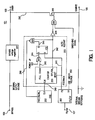
- FIG 1 shows one embodiment of an integrated power supply controller circuit with improved fault condition protection in accordance with the teachings of the present invention.
- Figure 2 is a timing diagram showing one embodiment of power up, normal operation and auto-restart in a power supply controller in accordance with the teachings of the present invention.
- Figure 3 is a timing diagram showing one embodiment of momentary fault recovery in a power supply controller in accordance with the teachings of the present invention.
- Figure 4 shows one embodiment of a switched mode power supply in accordance with teachings of the present invention.
- Embodiments of methods and apparatuses for fault condition protection of a switched mode power supply are disclosed.
- numerous specific details are set forth in order to provide a thorough understanding of the present invention. It will be apparent, however, to one having ordinary skill in the art that the specific detail need not be employed to practice the present invention. In other instances, well-known materials or methods have not been described in detail in order to avoid obscuring the present invention.
- a fault condition in the power supply may result from an open loop condition, which may be a result of a power supply output short circuit condition or a power supply overload condition.
- the power supply overload condition may be a result of a power supply input under-voltage condition.
- the off-time or the duration of a disable period of the initial auto-restart cycle or cycles is shortened significantly compared to the off-time or the duration of disable periods of subsequent auto-restart cycles. For faults with short duration, the recovery time of the power supply is reduced due to the shortened off-time of the initial auto-restart cycle or cycles.
- the protection provided by the auto-restart for a power supply in accordance with the teachings of the present invention is not compromised as, except for the auto-restart cycle or cycles, the off-time of subsequent cycles are not shortened.
- a fixed number of auto-restart cycles are shortened after the detection of a fault condition and the subsequent auto-restart cycles have longer durations.
- the fault condition is not detected until after the power supply has been in regulation. Only the first auto-restart cycle is shortened in one embodiment of the present invention. This modification allows a power supply to recover from momentary fault conditions with reduced delay.
- the on-time is 50ms and the off-time of the first auto-restart cycle is set to a much shorter value of, for example, 200ms or four times of on-time while leaving the off-time of all subsequent auto-restart cycles unchanged (one second or twenty times of on-time in this case).
- a power supply in accordance with the teachings of the present invention makes its first restart attempt in 200ms and then, if not successful; follows up with one subsequent attempt every 1.05 seconds. This allows the power supply to recover quickly from a momentary fault condition without compromising the auto-restart protection against faults persisting over longer time duration.
- time durations are provided only for explanation purposes and other time durations may be employed in accordance with the teachings of the present invention.
- an implementation in accordance with the teachings of the present invention includes a switching device for controlling, regulating or modulating power delivered to the output and a timer coupled to the switching device and to the feedback signal.
- the timer When a fault condition occurs, the timer enables the switching device to deliver power to the output for a first predetermined period (on-time), which is then followed by the timer disabling the switching device to prevent power delivery to the output for a second predetermined period (off-time).
- the switching device may be alternately enabled for the on-time and disabled for the off-time when the fault condition persists. This function is known as auto-restart.
- the switching device may be a power transistor.
- the timer may be a digital counter. An oscillator with a predetermined frequency may be coupled to the counter. The oscillator may have a control input for selecting between two predetermined frequencies: one fast, one slow.
- the off-time is much longer than the on-time, which in one embodiment is accomplished by running the oscillator at the fast frequency during on-time and at the slow frequency during off-time.
- the off-time of the first auto-restart cycle may be shortened by running the oscillator at the fast frequency instead of the default slow frequency.
- the on-times use the fast frequency while the off-times except for the off-time of the first auto-restart cycle use the slow frequency.
- the on-time and off-time are controlled by a signal decoded from the counter output according to desired on-time to off-time ratio.
- counter is reset to zero count.
- On-time starts from zero count and ends at n count.
- Off-time starts from n+1 count and ends at full count.
- a latch is added in one embodiment. The output of the latch determines which frequency is to be used for the off-time.
- the latch being set selects the slow frequency and the latch being reset selects the fast frequency.
- the on-time uses the fast frequency regardless of the state of the latch output.
- the latch is automatically set to select the slow frequency for the off-time.
- a feedback signal is generated from the power supply output, which in turn resets the latch and changes the selection to the fast frequency. Consequently, when a fault condition occurs, auto-restart begins with a short cycle providing an opportunity for the power supply to recover quickly if the fault is short in duration.
- off-time ends and the counter reaches full count.
- a full count signal is then generated to set the latch and selects the slow frequency. This ensures the use of slow frequency for the off-time of subsequent cycles if auto-restart continues as a result of a persisting fault.
- the power supply Upon the removal of the fault, the power supply restarts and the output reaches regulation. A feedback signal is then generated, which once again resets the latch and selects the fast frequency. Notice that, at this point, the power supply is back to the same status as it was first time after power up. For faults with a short duration, this fault removal process happens at the end of the first auto-restart cycle and the recovery time is short. For faults with longer duration, this happens at the end of a later cycle but the process is the same.
- Figure 1 shows one embodiment of an integrated power supply controller circuit 101.
- a BYPASS voltage regulator 201 is connected to both the DRAIN terminal 103 and the BYPASS terminal 105 to generate a stable voltage for internal supply use.
- a FB/UV circuit 203 is coupled to the FB/UV terminal 107 to receive a combined feedback and line voltage signal. The FB/UV circuit 203 checks line under voltage and separates the combined signal into a feedback signal 241 and a line under voltage signal 250.
- An auto-restart circuit 200 consists of a counter 220, an OR gate 221, an RS latch 222 and an NAND gate 223.
- feedback signal 241 is a digital signal having two states.
- the counter 220 receives a clock signal 240 from an oscillator 202 and generates an OFF/ON_signal 242 to control the on-time and the off-time of the auto-restart operation.
- latch 222 is set before counting begins, and counter 220 is reset before counting begins.
- the OFF/ON_ signal 242 stays low from zero count up to n count indicating auto-restart on-time.
- the OFF/ON_signal 242 goes high at n count and stays high till full count indicating auto-restart off-time.
- a full count signal 243 is generated at full count, which sets the latch 222 via OR gate 221.
- the latch output 245 is coupled to one input of NAND gate 223.
- the other input of the NAND gate 223 receives the OFF/ON_signal 242 from counter 220.
- the output of NAND gate 223 connects to the FAST/SLOW_input of oscillator 202.
- a high signal at the FAST/SLOW_ input selects the predetermined fast frequency for the oscillator 202 while a low signal selects the predetermined slow frequency.
- latch 222 is reset, the signal at the FAST/SLOW_input (signal 246) is forced high by NAND gate 223. This forces the off-time to run the same frequency as the on-time (fast frequency).
- latch 222 is set, the signal at the FAST/SLOW_input is equal to the OFF/ON_signal 242 which allows the off-time to run the opposite frequency as the on-time (slow frequency).
- the FB/UV circuit 203 receives a combined feedback and a line voltage signal from the FB/UV terminal 107. After separating the feedback signal from line voltage signal, FB/UV circuit 203 sends the FEEDBACK signal 241 to the RESET input of counter 220 and R input of latch 222. When power supply output reaches regulation, node 241 goes high resetting both counter 220 and latch 222.
- the OFF/ON_signal is also coupled to the input of the other AND gate 205 through inverter 204.
- the power MOSFET 206 or power switch coupled between DRAIN terminal 103 and SOURCE terminal 109 is disabled when OFF/ON_signal is high (auto-restart off-time) and enabled when OFF/ON_is low (auto-restart on-time).
- Figure 2 shows various modes of operation for one embodiment of a switched mode power supply with an auto-restart function in accordance with the teachings of the present invention.
- FEEDBACK signal 241 goes low, the power supply continues switching for a duration of the auto-restart on-time. The maximum available power is delivered to power supply output during this period. If FEEDBACK signal 241 stays low during this time, a fault condition is detected at the end of this period and the first auto-restart off-time begins. Because the fast frequency is selected, this first cycle of the off-time is short compare to subsequent off-times. Thus, the fault condition is detected in one embodiment after the FEEDBACK signal 241 has been idle or has not changed states for a predetermined period of time.
- Figure 3 illustrates the fast recovery of one embodiment of a power supply in accordance with the teachings of the present invention from a momentary fault.
- the frequency is shown as fast for the first auto-restart cycle and slow for the second auto-restart cycle, only the beginning of which is shown.
- the power supply reaches regulation and resets latch 222 before the second off-time begins.
- FIG. 4 shows one embodiment of a switched mode power supply 401 with an input for receiving energy from a rectified and filtered AC input 403 and a DC output 405 for generating a regulated DC voltage.
- power supply 401 includes a power supply controller 600 coupled to an energy transfer element 601.
- power supply controller 600 is an integrated circuit including four terminals: BYPASS, FB/UV, DRAIN and SOURCE.
- the energy transfer element is a transformer with a primary winding 640 and a secondary winding 641.
- energy transfer element 601 includes a transformer, coupled inductors, an inductor or the like. Output voltage is sensed by Zener diode 621 and an LED of an opto-coupler 602.
- the feedback signal generated from the secondary winding 641 is coupled back to the FB/UV terminal of the power supply controller 600 via the opto-coupler 602.
- An on-chip high voltage power MOSFET is switched on and off by the power supply controller 600 to control the transfer of energy from input 403 to output 405, and thus, regulating the output voltage according to the feedback signal.
Landscapes
- Engineering & Computer Science (AREA)
- Power Engineering (AREA)
- Dc-Dc Converters (AREA)
- Emergency Protection Circuit Devices (AREA)
Abstract
Description
Claims (22)
- A power supply circuit, comprising:a first terminal to be coupled to an energy transfer element having an energy transfer element input and output, the energy transfer element input coupled to a first terminal of a power supply input;a second terminal to be coupled to a second terminal of the power supply input;a third terminal to be coupled to receive at least feedback information of a power supply output;a control circuitry coupled to the first, second and third terminals, the control circuitry to control power delivered to the power supply output from the power supply input in response to said at least feedback information of the power supply output; andan auto-restart circuit coupled to the third terminal and the control circuitry, the auto-restart circuit coupled to the control circuitry to repeatedly enable and disable the power supply during a fault condition, wherein a duration of at least one disable period following a detection of a fault condition of the power supply is smaller than durations of subsequent disable periods.
- The power supply circuit of claim 1 wherein the control circuitry comprises a power switch coupled between the first and second terminals, the power switch switched in response to a switching signal to control the power delivered to the power supply output from the power supply input.
- The power supply circuit of claim 1 or 2 wherein a duration of a first disable period following the detection of the fault condition of the power supply is smaller than durations of subsequent disable periods.
- The power supply circuit of claim 1, 2 or 3 wherein the detection of the fault condition of the power supply occurs after the power supply has been in regulation.
- The power supply circuit of any one previous claim wherein said at least one disable period following the detection of the fault condition of the power supply is a fixed number.
- A power supply, comprising:wherein a fixed number of disable periods following a detection of the power supply fault condition after the power supply has been in regulation have smaller durations than durations of subsequent disable periods.an energy transfer element having an energy transfer element input and an energy transfer element output, the energy transfer element input coupled to a first terminal of an input of the power supply, the energy transfer element output coupled to an output of the power supply;a power supply controller including a power switch coupled between the energy transfer element input and a second terminal of the input of the power supply, the power supply controller further coupled to the energy transfer element output, a feedback signal generated in response to the energy transfer element output, the power switch switched to modulate power delivered to the output of the power supply from the input of the power supply in response to the feedback signal; andan auto restart circuit included in the power supply controller coupled to repeatedly enable and disable the power supply during a power supply fault condition,
- The power supply according to any one previous claim wherein the power supply fault condition is an open loop condition.
- The power supply according to any one previous claim wherein the open loop condition is a result of at least one of a power supply output short circuit condition and a power supply overload condition.
- The power supply according to any one previous claim wherein the power supply overload condition is caused by a power supply input under-voltage condition.
- The power supply of claim 7 as appended to claim 6 only, wherein the open loop condition is detected by the power supply controller in response to the feedback signal being idle for a predetermined period of time.
- The power supply of claim 10 wherein the feedback signal is a digital signal with two states.
- The power supply of claim 11 wherein the feedback signal being idle for the predetermined period of time occurs when the feedback signal is in one of the two states for the predetermined period of time.
- The power supply of claim 10, 11 or 12 wherein the power supply is a switched mode power supply.
- The power supply of claim 10, 11, 12 or 13 wherein the power supply controller further coupled to receive the feedback signal from energy transfer element input to further detect a power supply input under-voltage condition.
- The power supply of any one of 10 to 14 claims wherein only a duration of a first disable period following the detection of the power supply fault condition has a smaller duration than the durations of the subsequent disable periods.
- A method, comprising:wherein a duration of one or more disable periods follow the detection of the fault condition in the power supply is smaller than a duration of subsequent disable periods.regulating a delivery of power from a power supply input to a power supply output;detecting a fault condition in the power supply; andrepeatedly enabling and disabling the power supply during the fault condition until the fault condition is no longer present in the power supply,
- The method of claim 16 wherein detecting the fault condition in the power supply includes detecting; an open loop condition in the power supply.
- The method of claim 17 wherein detecting the open loop condition in the power supply includes detecting at least one of a power supply output short circuit condition and a power supply output overload condition in the power supply.
- The method of claim 18 wherein the power supply output overload condition is caused by a power supply input under-voltage condition in the power supply.
- The method of any one of claims 16 to 19 wherein regulating the delivery of power from the power supply input to the power supply output includes switching a power switch in response to a switching signal, the power switch to switchably couple an energy transfer element of the power supply to the power supply input.
- A method according to any one of claims 16 to 20 wherein only a duration of a first disable period following the detection of the fault condition in the power supply is smaller than the duration of subsequent disable periods.
- A method according to any one of claims 16 to 21 wherein the detection of the fault condition in the power supply occurs after the power supply has been in regulation.
Applications Claiming Priority (4)
| Application Number | Priority Date | Filing Date | Title |
|---|---|---|---|
| US92601 | 1979-11-08 | ||
| US27596201P | 2001-03-14 | 2001-03-14 | |
| US275962P | 2001-03-14 | ||
| US10/092,601 US6580593B2 (en) | 2001-03-14 | 2002-03-08 | Method and apparatus for fault condition protection of a switched mode power supply |
Publications (3)
| Publication Number | Publication Date |
|---|---|
| EP1241778A2 true EP1241778A2 (en) | 2002-09-18 |
| EP1241778A3 EP1241778A3 (en) | 2002-11-27 |
| EP1241778B1 EP1241778B1 (en) | 2004-06-02 |
Family
ID=26785840
Family Applications (1)
| Application Number | Title | Priority Date | Filing Date |
|---|---|---|---|
| EP02251781A Expired - Lifetime EP1241778B1 (en) | 2001-03-14 | 2002-03-13 | Method and apparatus for fault condition protection of a switched mode power supply |
Country Status (4)
| Country | Link |
|---|---|
| US (4) | US6580593B2 (en) |
| EP (1) | EP1241778B1 (en) |
| JP (2) | JP2002325433A (en) |
| DE (1) | DE60200563T2 (en) |
Cited By (5)
| Publication number | Priority date | Publication date | Assignee | Title |
|---|---|---|---|---|
| US6788514B2 (en) | 2001-03-14 | 2004-09-07 | Power Intergrations, Inc. | Method and apparatus for fault condition protection of a switched mode power supply |
| JP2007014196A (en) * | 2005-07-01 | 2007-01-18 | Power Integrations Inc | Method for detecting failure in switching power supply and detecting apparatus thereof |
| US7443052B2 (en) * | 2004-01-09 | 2008-10-28 | Koninklijke Philips Electronics N.V. | DC/DC converter and decentralized power generation system comprising a DC/DC converter |
| US9887532B2 (en) | 2015-01-14 | 2018-02-06 | Infineon Technologies Ag | Power switch device |
| EP3848768A1 (en) * | 2020-01-07 | 2021-07-14 | Hamilton Sundstrand Corporation | Fault monitoring systems for power supplies |
Families Citing this family (40)
| Publication number | Priority date | Publication date | Assignee | Title |
|---|---|---|---|---|
| US6882917B2 (en) | 1999-07-30 | 2005-04-19 | Oshkosh Truck Corporation | Steering control system and method |
| US6885920B2 (en) | 1999-07-30 | 2005-04-26 | Oshkosh Truck Corporation | Control system and method for electric vehicle |
| US7379797B2 (en) | 2001-01-31 | 2008-05-27 | Oshkosh Truck Corporation | System and method for braking in an electric vehicle |
| US6781357B2 (en) * | 2001-09-27 | 2004-08-24 | Power Integrations, Inc. | Method and apparatus for maintaining a constant load current with line voltage in a switch mode power supply |
| ITMI20040517A1 (en) * | 2004-03-18 | 2004-06-18 | St Microelectronics Srl | METHOD AND RELATED CIRCUIT FOR THE PROTECTION AGAINST THE MALFUNCTIONS OF THE FEEDBACK RING IN SWITCHING POWER SUPPLIES |
| CN100462897C (en) * | 2004-11-30 | 2009-02-18 | 鸿富锦精密工业(深圳)有限公司 | Computer system with restart control circuit |
| US7272025B2 (en) * | 2005-01-18 | 2007-09-18 | Power Integrations, Inc. | Method and apparatus to control either a regulated or an unregulated output of a switching power supply |
| US7679874B2 (en) * | 2005-07-25 | 2010-03-16 | Semiconductor Components Industries, L.L.C. | Power overload detection method and structure therefor |
| CN2938554Y (en) * | 2006-08-29 | 2007-08-22 | Bcd半导体制造有限公司 | Switch mode power supply and its overvoltage protection circuit |
| US7719811B2 (en) * | 2006-09-08 | 2010-05-18 | Ford Global Technologies | FET monitoring and protecting system |
| US7576528B2 (en) | 2006-10-04 | 2009-08-18 | Power Integrations, Inc. | Control circuit responsive to an impedance |
| US7518885B2 (en) * | 2006-10-04 | 2009-04-14 | Power Integrations, Inc. | Method and apparatus for a control circuit with multiple operation modes |
| US7502236B2 (en) | 2006-10-04 | 2009-03-10 | Power Integrations, Inc. | Power supply controller responsive to a feedforward signal |
| JP4938467B2 (en) * | 2007-01-12 | 2012-05-23 | 株式会社日立製作所 | Power conversion device for motor drive, motor drive device, motor, and motor drive method |
| KR100861283B1 (en) * | 2007-03-31 | 2008-10-01 | 엘지전자 주식회사 | Refrigerator and its operation method |
| US8077483B2 (en) | 2007-04-06 | 2011-12-13 | Power Integrations, Inc. | Method and apparatus for sensing multiple voltage values from a single terminal of a power converter controller |
| US8077486B2 (en) | 2007-04-06 | 2011-12-13 | Power Integrations, Inc. | Method and apparatus for power converter fault condition detection |
| WO2010035168A1 (en) * | 2008-09-23 | 2010-04-01 | Koninklijke Philips Electronics, N.V. | Current limiting controlling for power supply, e.g. led driver, having automatic reset |
| US8392764B2 (en) * | 2009-11-16 | 2013-03-05 | Cooper Technologies Company | Methods and systems for identifying and configuring networked devices |
| WO2013067704A1 (en) * | 2011-11-10 | 2013-05-16 | General Electric Company | Device for failure protection in lighting devices having light emitting diodes |
| US9300326B2 (en) * | 2012-11-01 | 2016-03-29 | Qualcomm Incorporated | Prevention of output supply boosting upon removal of input adapter |
| JP5679241B1 (en) * | 2013-09-27 | 2015-03-04 | 株式会社京三製作所 | Voltage source DC power supply and control method for voltage source DC power supply |
| US9960665B2 (en) * | 2015-12-02 | 2018-05-01 | Astec International Limited | Power supplies having a single isolation device for feedback and fault detection |
| US10566791B2 (en) | 2016-09-29 | 2020-02-18 | Enel X North America, Inc. | Automated validation, estimation, and editing processor |
| US10298012B2 (en) | 2016-09-29 | 2019-05-21 | Enel X North America, Inc. | Network operations center including automated validation, estimation, and editing configuration engine |
| US10203714B2 (en) | 2016-09-29 | 2019-02-12 | Enel X North America, Inc. | Brown out prediction system including automated validation, estimation, and editing rules configuration engine |
| US10170910B2 (en) * | 2016-09-29 | 2019-01-01 | Enel X North America, Inc. | Energy baselining system including automated validation, estimation, and editing rules configuration engine |
| US10461533B2 (en) | 2016-09-29 | 2019-10-29 | Enel X North America, Inc. | Apparatus and method for automated validation, estimation, and editing configuration |
| US10291022B2 (en) | 2016-09-29 | 2019-05-14 | Enel X North America, Inc. | Apparatus and method for automated configuration of estimation rules in a network operations center |
| US10423186B2 (en) | 2016-09-29 | 2019-09-24 | Enel X North America, Inc. | Building control system including automated validation, estimation, and editing rules configuration engine |
| US9735564B1 (en) | 2016-10-28 | 2017-08-15 | International Business Machines Corporation | Protection against abnormal overpower of electrical equipment |
| FR3066061B1 (en) | 2017-05-03 | 2019-06-21 | Stmicroelectronics (Rousset) Sas | DIGITAL-ANALOG CONVERTER |
| FR3066060B1 (en) * | 2017-05-03 | 2020-03-27 | Stmicroelectronics (Rousset) Sas | CUT-OFF POWER CONTROL |
| US10355583B1 (en) | 2018-05-21 | 2019-07-16 | Power Integrations, Inc. | Power converter fault detection by counting request pulses |
| EP3874591A1 (en) * | 2018-10-30 | 2021-09-08 | Agility Power Systems LLC | High efficiency, parallel, power conversion system with adaptive dynamic efficiency optimization |
| US11316336B2 (en) | 2018-11-14 | 2022-04-26 | Hewlett Packard Enterprise Development Lp | Systems and methods for input overcurrent protection |
| US12021439B2 (en) | 2019-05-24 | 2024-06-25 | Power Integrations, Inc. | Switching delay for communication |
| US11336083B2 (en) * | 2019-11-05 | 2022-05-17 | Hamilton Sundstrand Corporation | Power converter monitor and method of use |
| EP4186733B1 (en) | 2021-11-24 | 2025-01-01 | Power Integrations, Inc. | Active discharge of an electric drive system |
| US11996795B2 (en) | 2022-03-28 | 2024-05-28 | Power Integrations, Inc. | Motor alignment control |
Family Cites Families (33)
| Publication number | Priority date | Publication date | Assignee | Title |
|---|---|---|---|---|
| US4266259A (en) * | 1979-09-04 | 1981-05-05 | General Electric Company | Long-time and short-time overcurrent signal processor for circuit breaker static trip units |
| US4394703A (en) | 1981-12-24 | 1983-07-19 | Gte Automatic Electric Labs Inc. | Load protecting arrangement |
| JPS6091822A (en) * | 1983-10-24 | 1985-05-23 | 富士通株式会社 | Power source control circuit |
| JPS60167014A (en) | 1984-02-08 | 1985-08-30 | Toyo Commun Equip Co Ltd | Automatic resetting type overload protecting circuit |
| JPH0755060B2 (en) * | 1984-10-23 | 1995-06-07 | 株式会社日立製作所 | Inverter retry controller |
| US4685020A (en) | 1985-05-06 | 1987-08-04 | International Business Machines Corp. | Shutdown circuit for blocking oscillator power supply |
| JPS6234213A (en) * | 1985-08-08 | 1987-02-14 | Fujitsu Ltd | Constant current power supply circuit |
| US4916573A (en) * | 1985-10-25 | 1990-04-10 | S & C Electric Company | Control circuit for a circuit interrupter |
| US4887199A (en) | 1986-02-07 | 1989-12-12 | Astec International Limited | Start circuit for generation of pulse width modulated switching pulses for switch mode power supplies |
| CA1287103C (en) | 1986-04-22 | 1991-07-30 | Jim Pinard | Cmos latch-up recovery circuit |
| US4845594A (en) * | 1986-07-01 | 1989-07-04 | Basler Electric Company | Reclosing relay with nonvolatile memory of operations |
| JPH0677534B2 (en) * | 1989-04-10 | 1994-10-05 | 松下電器産業株式会社 | Heating cookers such as rice cookers |
| JP3096082B2 (en) | 1991-03-26 | 2000-10-10 | 株式会社東芝 | Reclosing circuit of PCM current differential relay |
| JPH0522837A (en) * | 1991-07-09 | 1993-01-29 | Honda Motor Co Ltd | Portable power supply |
| US5311392A (en) * | 1991-08-30 | 1994-05-10 | Siemens Energy & Automation, Inc. | Dual processor electric power trip unit |
| US5264782A (en) | 1992-08-10 | 1993-11-23 | International Business Machines Corporation | Dropout recovery circuit |
| US5335162A (en) * | 1993-01-15 | 1994-08-02 | Toko America, Inc. | Primary side controller for regulated power converters |
| US5510699A (en) | 1994-05-31 | 1996-04-23 | Deutsche Itt Industries Gmbh | Voltage regulator |
| DE69521287T2 (en) | 1995-03-24 | 2002-05-02 | Co.Ri.M.Me. Consorzio Per La Ricerca Sulla Microelettronica Nel Mezzogiorno, Catania | Circuit arrangement for generating a reference voltage and detection of a supply voltage drop and associated method |
| US5550437A (en) | 1995-04-06 | 1996-08-27 | France/Scott Fetzer Company | Electronic dimmable gas tube power supply with overvoltage protection |
| US5805401A (en) | 1995-08-30 | 1998-09-08 | Cherry Semiconductor Corporation | Undervoltage lockout circuit with sleep pin |
| US5698970A (en) | 1996-04-16 | 1997-12-16 | Exar Corporation | Switching shunt regulator |
| US5798635A (en) | 1996-06-20 | 1998-08-25 | Micro Linear Corporation | One pin error amplifier and switched soft-start for an eight pin PFC-PWM combination integrated circuit converter controller |
| US5949154A (en) | 1996-11-15 | 1999-09-07 | Thomson Consumer Electronics, Inc. | Auxiliary power supply control |
| US5796596A (en) | 1996-11-15 | 1998-08-18 | Thomson Consumer Electronics, Inc. | Fault control circuit for switched power supply |
| US5874841A (en) | 1997-07-28 | 1999-02-23 | Philips Electronics North America Corporation | Sample-and-hold circuit for a switched-mode power supply |
| JPH11252907A (en) * | 1998-02-25 | 1999-09-17 | Nec Tohoku Ltd | Switching power unit |
| US6239960B1 (en) * | 1998-04-03 | 2001-05-29 | Basler Electric Company | Reconfigurable reclosing relay |
| US6147883A (en) | 1998-11-16 | 2000-11-14 | Power Integrations, Inc. | Output feedback and under-voltage detection |
| JP2000324817A (en) | 1999-05-17 | 2000-11-24 | Murata Mfg Co Ltd | Power supply circuit |
| US6480043B2 (en) * | 1999-05-24 | 2002-11-12 | Semiconductor Components Industries Llc | Circuit and method for protecting a switching power supply from a fault condition |
| US6154377A (en) | 1999-10-08 | 2000-11-28 | Power Integrations, Inc. | Method and apparatus reducing overshoot in a power supply controller |
| US6580593B2 (en) | 2001-03-14 | 2003-06-17 | Power Integrations, Inc. | Method and apparatus for fault condition protection of a switched mode power supply |
-
2002
- 2002-03-08 US US10/092,601 patent/US6580593B2/en not_active Expired - Lifetime
- 2002-03-13 EP EP02251781A patent/EP1241778B1/en not_active Expired - Lifetime
- 2002-03-13 DE DE60200563T patent/DE60200563T2/en not_active Expired - Lifetime
- 2002-03-14 JP JP2002070105A patent/JP2002325433A/en active Pending
-
2003
- 2003-05-08 US US10/435,152 patent/US6788514B2/en not_active Expired - Fee Related
-
2004
- 2004-05-19 US US10/850,487 patent/US7218495B2/en not_active Expired - Fee Related
-
2007
- 2007-04-03 US US11/732,612 patent/US7489491B2/en not_active Expired - Fee Related
-
2010
- 2010-03-29 JP JP2010075707A patent/JP5580635B2/en not_active Expired - Fee Related
Cited By (11)
| Publication number | Priority date | Publication date | Assignee | Title |
|---|---|---|---|---|
| US6788514B2 (en) | 2001-03-14 | 2004-09-07 | Power Intergrations, Inc. | Method and apparatus for fault condition protection of a switched mode power supply |
| US7218495B2 (en) | 2001-03-14 | 2007-05-15 | Power Integrations, Inc. | Method and apparatus for fault condition protection of a switched mode power supply |
| US7489491B2 (en) | 2001-03-14 | 2009-02-10 | Power Integrations, Inc. | Method and apparatus for fault condition protection of a switched mode power supply |
| US7443052B2 (en) * | 2004-01-09 | 2008-10-28 | Koninklijke Philips Electronics N.V. | DC/DC converter and decentralized power generation system comprising a DC/DC converter |
| JP2007014196A (en) * | 2005-07-01 | 2007-01-18 | Power Integrations Inc | Method for detecting failure in switching power supply and detecting apparatus thereof |
| EP1744439A3 (en) * | 2005-07-01 | 2008-04-02 | Power Integrations, Inc. | Method and apparatus for fault detection in a switching power supply |
| US7539028B2 (en) | 2005-07-01 | 2009-05-26 | Power Integrations, Inc. | Method and apparatus for fault detection in a switching power supply |
| US7760518B2 (en) | 2005-07-01 | 2010-07-20 | Power Integrations, Inc. | Method and apparatus for fault detection in a switching power supply |
| US9887532B2 (en) | 2015-01-14 | 2018-02-06 | Infineon Technologies Ag | Power switch device |
| EP3848768A1 (en) * | 2020-01-07 | 2021-07-14 | Hamilton Sundstrand Corporation | Fault monitoring systems for power supplies |
| US11209494B2 (en) | 2020-01-07 | 2021-12-28 | Hamilton Sundstrand Corporation | Fault monitoring systems for power supplies |
Also Published As
| Publication number | Publication date |
|---|---|
| DE60200563D1 (en) | 2004-07-08 |
| US6788514B2 (en) | 2004-09-07 |
| US7218495B2 (en) | 2007-05-15 |
| DE60200563T2 (en) | 2005-06-30 |
| US20040212942A1 (en) | 2004-10-28 |
| US6580593B2 (en) | 2003-06-17 |
| EP1241778A3 (en) | 2002-11-27 |
| JP2002325433A (en) | 2002-11-08 |
| EP1241778B1 (en) | 2004-06-02 |
| US20020131280A1 (en) | 2002-09-19 |
| US7489491B2 (en) | 2009-02-10 |
| US20030197994A1 (en) | 2003-10-23 |
| JP5580635B2 (en) | 2014-08-27 |
| US20070188960A1 (en) | 2007-08-16 |
| JP2010154750A (en) | 2010-07-08 |
Similar Documents
| Publication | Publication Date | Title |
|---|---|---|
| EP1241778B1 (en) | Method and apparatus for fault condition protection of a switched mode power supply | |
| JP4797637B2 (en) | Resonant switching power supply | |
| JP5314111B2 (en) | Method and apparatus for conditional response to fault conditions in switching power supplies | |
| US7453709B2 (en) | Method and apparatus for increasing the power capability of a power supply | |
| CN107660324B (en) | Primary-side startup method and circuit arrangement for series-parallel resonant power converters | |
| EP1226648B1 (en) | Protecting switching power supply from fault condition | |
| JP4156819B2 (en) | Method and apparatus for reducing audible noise in switching regulators | |
| US6914793B2 (en) | Method and apparatus providing a multi-function terminal for a power supply controller | |
| JP3883826B2 (en) | Switching power supply | |
| CN102480236B (en) | Switching power unit and the image processing system with switching power unit | |
| US7075802B2 (en) | Semiconductor device for controlling switching power supply | |
| CN103066825B (en) | A kind of power off method and power supply | |
| KR20180013897A (en) | Power reduction in power converter in standby mode | |
| US6385060B1 (en) | Switching power supply with reduced energy transfer during a fault condition | |
| KR20180020922A (en) | Resonant capacitor stabilizer in resonant converters | |
| US20130271876A1 (en) | Switching control circuit and switching power supply apparatus | |
| US7116563B2 (en) | Dual mode over-current protection for switching mode power converter | |
| US6804126B2 (en) | Power supply start up circuit | |
| US6154377A (en) | Method and apparatus reducing overshoot in a power supply controller | |
| JP2004080859A (en) | Switching power supply control circuit | |
| JP4374714B2 (en) | Switching power supply | |
| JP2006166561A (en) | Power supply | |
| HK1150908A (en) | Protecting switching power supply from fault condition |
Legal Events
| Date | Code | Title | Description |
|---|---|---|---|
| PUAI | Public reference made under article 153(3) epc to a published international application that has entered the european phase |
Free format text: ORIGINAL CODE: 0009012 |
|
| AK | Designated contracting states |
Kind code of ref document: A2 Designated state(s): AT BE CH CY DE DK ES FI FR GB GR IE IT LI LU MC NL PT SE TR |
|
| AX | Request for extension of the european patent |
Free format text: AL;LT;LV;MK;RO;SI |
|
| PUAL | Search report despatched |
Free format text: ORIGINAL CODE: 0009013 |
|
| RIC1 | Information provided on ipc code assigned before grant |
Free format text: 7H 02M 3/335 A, 7H 02H 7/122 B, 7H 02M 1/00 B |
|
| AK | Designated contracting states |
Kind code of ref document: A3 Designated state(s): AT BE CH CY DE DK ES FI FR GB GR IE IT LI LU MC NL PT SE TR |
|
| AX | Request for extension of the european patent |
Free format text: AL;LT;LV;MK;RO;SI |
|
| 17P | Request for examination filed |
Effective date: 20021224 |
|
| 17Q | First examination report despatched |
Effective date: 20030403 |
|
| AKX | Designation fees paid |
Designated state(s): DE FR GB IT NL SE |
|
| GRAP | Despatch of communication of intention to grant a patent |
Free format text: ORIGINAL CODE: EPIDOSNIGR1 |
|
| RTI1 | Title (correction) |
Free format text: METHOD AND APPARATUS FOR FAULT CONDITION PROTECTION OF A SWITCHED MODE POWER SUPPLY |
|
| GRAS | Grant fee paid |
Free format text: ORIGINAL CODE: EPIDOSNIGR3 |
|
| GRAA | (expected) grant |
Free format text: ORIGINAL CODE: 0009210 |
|
| AK | Designated contracting states |
Kind code of ref document: B1 Designated state(s): DE FR GB IT NL SE |
|
| REG | Reference to a national code |
Ref country code: GB Ref legal event code: FG4D |
|
| REF | Corresponds to: |
Ref document number: 60200563 Country of ref document: DE Date of ref document: 20040708 Kind code of ref document: P |
|
| REG | Reference to a national code |
Ref country code: SE Ref legal event code: TRGR |
|
| ET | Fr: translation filed | ||
| PLBE | No opposition filed within time limit |
Free format text: ORIGINAL CODE: 0009261 |
|
| STAA | Information on the status of an ep patent application or granted ep patent |
Free format text: STATUS: NO OPPOSITION FILED WITHIN TIME LIMIT |
|
| 26N | No opposition filed |
Effective date: 20050303 |
|
| PGFP | Annual fee paid to national office [announced via postgrant information from national office to epo] |
Ref country code: SE Payment date: 20130327 Year of fee payment: 12 |
|
| PGFP | Annual fee paid to national office [announced via postgrant information from national office to epo] |
Ref country code: NL Payment date: 20140326 Year of fee payment: 13 |
|
| PGFP | Annual fee paid to national office [announced via postgrant information from national office to epo] |
Ref country code: FR Payment date: 20140317 Year of fee payment: 13 Ref country code: IT Payment date: 20140321 Year of fee payment: 13 |
|
| PGFP | Annual fee paid to national office [announced via postgrant information from national office to epo] |
Ref country code: GB Payment date: 20140327 Year of fee payment: 13 |
|
| PGFP | Annual fee paid to national office [announced via postgrant information from national office to epo] |
Ref country code: DE Payment date: 20140327 Year of fee payment: 13 |
|
| REG | Reference to a national code |
Ref country code: SE Ref legal event code: EUG |
|
| PG25 | Lapsed in a contracting state [announced via postgrant information from national office to epo] |
Ref country code: SE Free format text: LAPSE BECAUSE OF NON-PAYMENT OF DUE FEES Effective date: 20140314 |
|
| REG | Reference to a national code |
Ref country code: DE Ref legal event code: R119 Ref document number: 60200563 Country of ref document: DE |
|
| GBPC | Gb: european patent ceased through non-payment of renewal fee |
Effective date: 20150313 |
|
| REG | Reference to a national code |
Ref country code: NL Ref legal event code: MM Effective date: 20150401 |
|
| PG25 | Lapsed in a contracting state [announced via postgrant information from national office to epo] |
Ref country code: IT Free format text: LAPSE BECAUSE OF NON-PAYMENT OF DUE FEES Effective date: 20150313 |
|
| REG | Reference to a national code |
Ref country code: FR Ref legal event code: ST Effective date: 20151130 |
|
| PG25 | Lapsed in a contracting state [announced via postgrant information from national office to epo] |
Ref country code: GB Free format text: LAPSE BECAUSE OF NON-PAYMENT OF DUE FEES Effective date: 20150313 Ref country code: DE Free format text: LAPSE BECAUSE OF NON-PAYMENT OF DUE FEES Effective date: 20151001 |
|
| PG25 | Lapsed in a contracting state [announced via postgrant information from national office to epo] |
Ref country code: FR Free format text: LAPSE BECAUSE OF NON-PAYMENT OF DUE FEES Effective date: 20150331 |
|
| PG25 | Lapsed in a contracting state [announced via postgrant information from national office to epo] |
Ref country code: NL Free format text: LAPSE BECAUSE OF NON-PAYMENT OF DUE FEES Effective date: 20150401 |