EP1241680A1 - Core spray sparger T-Box attachment with clamp - Google Patents
Core spray sparger T-Box attachment with clamp Download PDFInfo
- Publication number
- EP1241680A1 EP1241680A1 EP02251783A EP02251783A EP1241680A1 EP 1241680 A1 EP1241680 A1 EP 1241680A1 EP 02251783 A EP02251783 A EP 02251783A EP 02251783 A EP02251783 A EP 02251783A EP 1241680 A1 EP1241680 A1 EP 1241680A1
- Authority
- EP
- European Patent Office
- Prior art keywords
- sparger
- clamp
- box
- anchor
- extending
- Prior art date
- Legal status (The legal status is an assumption and is not a legal conclusion. Google has not performed a legal analysis and makes no representation as to the accuracy of the status listed.)
- Granted
Links
Images


Classifications
-
- G—PHYSICS
- G21—NUCLEAR PHYSICS; NUCLEAR ENGINEERING
- G21C—NUCLEAR REACTORS
- G21C15/00—Cooling arrangements within the pressure vessel containing the core; Selection of specific coolants
- G21C15/18—Emergency cooling arrangements; Removing shut-down heat
-
- G—PHYSICS
- G21—NUCLEAR PHYSICS; NUCLEAR ENGINEERING
- G21C—NUCLEAR REACTORS
- G21C13/00—Pressure vessels; Containment vessels; Containment in general
- G21C13/02—Details
- G21C13/032—Joints between tubes and vessel walls, e.g. taking into account thermal stresses
- G21C13/036—Joints between tubes and vessel walls, e.g. taking into account thermal stresses the tube passing through the vessel wall, i.e. continuing on both sides of the wall
-
- Y—GENERAL TAGGING OF NEW TECHNOLOGICAL DEVELOPMENTS; GENERAL TAGGING OF CROSS-SECTIONAL TECHNOLOGIES SPANNING OVER SEVERAL SECTIONS OF THE IPC; TECHNICAL SUBJECTS COVERED BY FORMER USPC CROSS-REFERENCE ART COLLECTIONS [XRACs] AND DIGESTS
- Y02—TECHNOLOGIES OR APPLICATIONS FOR MITIGATION OR ADAPTATION AGAINST CLIMATE CHANGE
- Y02E—REDUCTION OF GREENHOUSE GAS [GHG] EMISSIONS, RELATED TO ENERGY GENERATION, TRANSMISSION OR DISTRIBUTION
- Y02E30/00—Energy generation of nuclear origin
- Y02E30/30—Nuclear fission reactors
Definitions
- This invention relates generally to nuclear reactors and more particularly, to apparatus and methods for repairing piping within reactor pressure vessels of such reactors.
- a reactor pressure vessel (RPV) of a boiling water reactor (BWR) typically has a generally cylindrical shape and is closed at both ends, e.g., by a bottom head and a removable top head.
- a core shroud, or shroud typically surrounds the core and is supported by a shroud support structure.
- Boiling water reactors have numerous piping systems, and such piping systems are utilized, for example, to transport water throughout the RPV.
- core spray piping is used to deliver water from outside the RPV to core spray spargers inside the RPV.
- the core spray piping and spargers deliver water flow to the reactor core.
- Intergranular stress corrosion cracking is a known phenomenon occurring in reactor components, such as structural members, piping, fasteners, and welds, exposed to high temperature water.
- the reactor components are subject to a variety of stresses associated with, for example, differences in thermal expansion, the operating pressure needed for the containment of the reactor cooling water, and other sources such as residual stresses from welding, cold working and other inhomogeneous metal treatments.
- water chemistry, welding, heat treatment and radiation can increase the susceptibility of metal in a component to IGSCC.
- One area of susceptibility in the core spray piping is the welded joints between the sparger T-box and its associated distribution headers.
- the sparger T-box is the junction where the core spray downcomer supply pipe penetrates the shroud branches to distribution sparger pipes.
- the core spray system prevents excessive fuel clad temperature in the event of a Loss of Coolant Accident (LOCA) by delivering cooling water to the core region of the reactor. In the event that through-wall circumferential cracking should occur at these welded joints, the system may be compromised.
- LOCA Loss of Coolant Accident
- a core spray sparger T-box attachment assembly for a nuclear reactor pressure vessel includes a downcomer pipe coupling and a sparger T-box clamp.
- the pressure vessel includes a shroud, a sparger T-box penetrating the shroud, a plurality of sparger distribution header pipes coupled to the sparger T-box, and a downcomer pipe.
- the sparger header pipes include at least one sparger nozzle.
- the downcomer pipe coupling includes a cylindrical outer housing, a center portion, and a plurality of vanes extending from an inner surface of the outer housing to the center portion.
- the outer housing is coupled to a downcomer pipe at one end, and includes a flange extending from the opposite end.
- the center portion includes a threaded axial bore therethrough. A draw bolt threadedly engages the axial bore of the center portion, and connects the downcomer pipe coupling to the sparger T-box clamp.
- the sparger T-box clamp includes an anchor having a draw bolt opening, and a plurality of legs extending from a face of the anchor. The legs are configured to engage an inside surface of the shroud and are machined or trimmed so that the anchor face is parallel to the exterior surface of the sparger T-box.
- a first and a second clamp block are connected to opposite sides of the anchor with dove-tail joints. The clamp blocks are positioned to be substantially aligned with one another.
- Each clamp block includes a threaded stop bolt opening extending therethrough.
- a stop bolt extends through each stop bolt opening.
- Each stop bolt has a conical shaped distal end which is sized to mate with a conical shaped opening machined in the sparger distribution header pipes.
- a first and a second clamping element are connected to the first clamp block and second clamp blocks by a plurality of clamp bolts. Also, a first and a second stop bolt extending through said stop bolt opening of said first and said second clamp block respectively.
- a seal plate is coupled to the anchor with a plurality of adjusting screws.
- the seal plate includes a plurality of adjusting screw openings and a draw bolt opening sized to receive the draw bolt.
- the anchor include a plurality of threaded adjusting screw openings sized to recieve the adjusting screws.
- the above described core spray sparger T-box attachment assembly mechanically couples the downcomer pipe to the shroud and sparger T-box. Also, the above described core spray sparger T-box attachment assembly provides a clamping system to provide structural integrity to the sparger T-box and to hold the welded joints together in the event that one or more welds fail.
- FIG 1 is a top sectional view of a boiling water nuclear reactor pressure vessel 10.
- Reactor pressure vessel 10 includes a vessel wall 12 and a shroud 14 which surrounds the reactor core (not shown) of pressure vessel 10.
- An annulus 16 is formed between vessel wall 12 and shroud 14. The space inside annulus 16 is limited with most reactor support piping located inside annulus 16.
- Cooling water is delivered to the reactor core during a loss of coolant accident through core spray distribution header pipes 18 and 20 which are connected to downcomer pipes 22 and 24 respectively.
- Downcomer pipes 22 and 24 are connected to shroud 14 through sparger T-boxes 26 and 28 respectively, which are attached to shroud 14 and internal sparger pipes 30.
- Distribution header pipes 18 and 20 diverge from an upper T-box 32 coupled to a safe end 42 of core spray nozzle 44. Header pipes 18 and 20 are coupled to upper T-box by pipe connectors 46 and 48 respectively.
- Pipe connectors 46 and 48 may be any pipe connectors known in the art, for example, ball flange connectors.
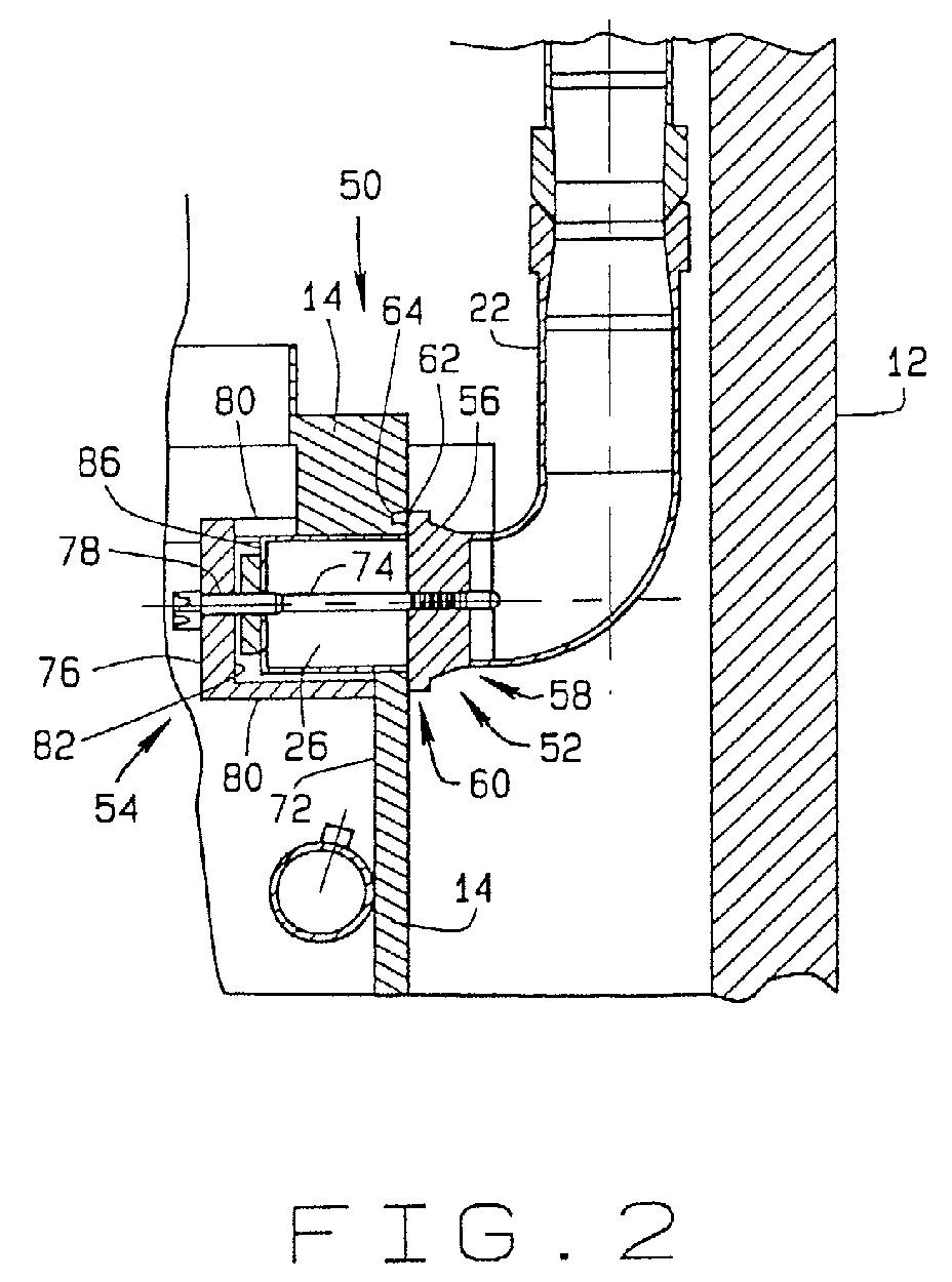
- FIG. 2 is a side sectional view of a sparger T-box attachment assembly 50 in accordance with an embodiment of the present invention.
- Sparger T-box attachment assembly 50 couples downcomer pipes 22 and 24 to sparger T-boxes 26 and 28 respectively, and clamps sparger pipes 30 to sparger T-boxes 26 and 28 to prevent separation of sparger pipes 30 from sparger T-boxes 26 and 28 in the event of a connecting weld failure.
- the sparger T-box attachment assembly includes a downcomer pipe coupling 52 and a sparger T-box clamp 54.
- downcomer pipe coupling 52 includes a cylindrical outer housing 56 having a first end 58 and a second end 60.
- First end 58 is configured to couple to downcomer pipe 22 by any suitable means, for example by welding.
- a flange 62 extends from second end 60 of outer housing 56.
- Flange 62 is received into a circular groove 64 machined into shroud 14.
- Groove 64 is located so as to be concentric with sparger T-box 26 penetration through shroud 14.
- a center portion 66 having a threaded axial bore 68 therethrough is connected to outer housing 56 by a plurality of vanes 70 extending from an inner surface 72 of outer housing 56 to center portion 66.
- a draw bolt 74 threadedly engages axial bore 68 of said center portion 66.
- Draw bolt 74 connects downcomer pipe coupling 52 to sparger T-box clamp 54.
- coupling 52 can be used to connect downcomer pipe 24 to sparger T-box 28.
- sparger T-box clamp 54 includes an anchor 76 having a draw bolt opening 78, and a plurality of legs 80 extending from a first face 82 of anchor 76. Legs 80 are configured to engage an inside surface 84 of shroud 14 and are machined or trimmed so that anchor face 82 is parallel to an exterior surface 86 of sparger T-box 26.
- a first and a second clamp block 88 and 90 are connected to opposite sides 92 and 94 of anchor 76.
- Clamp blocks 88 and 90 are positioned to be substantially aligned with one another.
- clamp blocks 88 and 90 are connected to sides 92 and 94 of anchor with dove-tail joints 96 and 98 respectively.
- Dove-tail joints 96 and 98 permit clamp blocks to move relative to anchor 76 which eliminates the imposition of any stress on the sparger pipe to sparger T-box welds.
- Clamp blocks 88 and 90 partially surround sparger pipe 30.
- Each clamp block 88 and 90 includes a threaded stop bolt opening 100 extending therethrough.
- a stop bolt 102 extends through each stop bolt opening 100.
- Each stop bolt 102 has a conical shaped distal end 104 which is sized to mate with a conical shaped opening 106 machined in sparger distribution header pipes 30.
- the conical shape of stop bolt end 104 and mating opening 106 minimizes interference with the flow stream in pipe 30 and also seals opening 106 to minimize leakage.
- clamping elements 108 and 110 are connected to clamp blocks 88 and 90 respectively by clamp bolts 112.
- Clamp bolts 112 extend through clamp bolt openings 114 in clamp blocks 88 and 90, and clamp bolt openings 116 in clamping elements 108 and 110.
- Spherical nuts 118 secure clamp bolts 112.
- Clamping elements 108 and 110 oppose clamp blocks 88 and 90 to provide a clamping action as clamp bolts 112 are tightened.
- a clamp bolt keeper 120 couples to clamp bolt head 122 to prevent clamp bolt 112 from loosening.
- Keeper 120 includes a crimp collar 124 threaded into a spherical collar 126.
- Crimp collar 124 to spherical collar 126 threads are opposite of the threads on clamp bolt 112. Specifically, in one embodiment, clamp bolt 112 has right hand threads, and spherical collar 124 has left hand threads. In an alternate embodiment, clamp bolt 112 has left hand threads, and spherical collar 124 has right hand threads.
- crimp collar 124 is deformed into flutes 128 in clamp bolt head 122.
- spherical seats 130 are machined into clamp blocks 88 and 90, and into clamping elements 108 and 110. Spherical seats 130 are concentrically aligned with clamp bolt openings 114 and 116. Also, spherical nut 118 and spherical collar 126 are keyed to clamp blocks 88 and 90 and clamping elements 108 and 110. Specifically, spherical nut 118 and spherical collar 126 includes a key portion 129, and spherical seats include a keyway 131 sized to receive key portion 129. The interface of key portion 129 with keyway 131 prevents spherical nut 118 and spherical collar 126 from rotating. Spherical seats 130 mitigate any bending forces imposed on clamp bolts 112 and provide flexibility to sparger T-box clamp 54 by permitting clamping elements 108 and 110 to move slightly to adjust and conform to the exterior contour of sparger pipe 30.
- Further clamping elements 108 and 110 include base portions 132 and 134 and engagement portions 136 and 138 respectively.
- Engagement portions 136 and 138 include cut-outs 140 sized to receive a sparger nozzle 142.
- a seal plate 144 is coupled to anchor 76 with adjusting screws 146.
- Seal plate 144 includes adjusting screw openings 148 and a draw bolt opening 150 sized to receive draw bolt 74 in a close tolerance fit.
- Anchor 76 includes threaded adjusting screw openings 152 sized to receive adjusting screws 146.
- a distal end portion 154 of adjusting screws 146 includes a circumferential groove 156 sized to receive a dowel pin 158 pressed into seal plate 144 to attach adjusting screws 146 to seal plate 144.
- a shank portion 160 of adjusting screws 146 are threaded into adjusting screw openings 152.
- seal plate 144 is advanced into close contact with exterior surface 86 of sparger T-box 26 to seal draw bolt opening 151 in T-box 26.
- Keepers 162 prevent adjusting screws from loosening. Keepers 162 mate with seats 164 concentric with adjusting screw openings 152. Keepers 162 include left hand threads (not shown) to mate with threads 165 in seats 164.
- anchor 76 further includes a rectangular depression 166 in a second face 168 of anchor 76.
- Draw bolt opening 78 is located in rectangular depression 166.
- a draw bolt keeper 170 having a rectangular portion 172 is received in rectangular depression 166 to prevent draw bolt 74 from loosening.
- Draw bolt keeper 170 also includes a crimp collar 173.
- FIG 12 is perspective view of anchor 76.
- Figure 13 is a perspective view of an anchor 174 in accordance with another embodiment of the present invention.
- Anchor 174 is similar to anchor 76 and includes a draw bolt opening 78, legs 80, keeper depression 164, adjusting screw openings 152, and adjusting bolt seats 164.
- Circular groove 64 is machined into shroud 14 by any suitable method, for example electrode discharge machining (EDM). Groove 64 is concentric with sparger T-box 26 penetration through shroud 14. A draw bolt opening is machined in T-box 26 and conical stop bolt openings 100 are machined in sparger pipes 30 equidistant from the center of sparger T-box 26.
- EDM electrode discharge machining
- First end 58 of outer housing is coupled to downcomer pipe 22 by any suitable means, for example welding.
- Flange 62 is then positioned in groove 64.
- T-box clamp 54 is positioned around sparger pipes 30 and sparger T-box 26 with anchor legs 80 engaging inner surface 72 of shroud 14.
- Draw bolt 74 with keeper 170 is inserted through draw bolt opening and threaded into axial bore 66 of coupling center portion 68 and tightened.
- Stop bolts 102 are threaded through stop bolt openings in clamp blocks 88 and 90 and tightened so as to seat in conical stop bolt openings 100 in sparger pipes 30.
- Clamp bolts extending through clamp bolt openings 114 and 116 in clamp blocks 88 and 90 and clamping elements 108 and 110 are tightened to exert a clamping force on sparger pipes 30. Adjusting screws are tightened to move seal plate 144 into contact with exterior surface 86 of sparger T-box 26. The crimp collars of all the keepers are deformed into flutes of the corresponding bolt heads to prevent the bolts from loosening.
- the above described core spray sparger T-box attachment assembly 50 mechanically couples downcomer pipe 22 to shroud 14 and sparger T-box 26. Also, the above described core spray sparger T-box attachment assembly 50 provides a clamping system to provide structural integrity to sparger T-box 26 and to hold the sparger pipes 30 to T-box 26 welded joints together in the event that one or more welds fail.
Abstract
Description
- This invention relates generally to nuclear reactors and more particularly, to apparatus and methods for repairing piping within reactor pressure vessels of such reactors.
- A reactor pressure vessel (RPV) of a boiling water reactor (BWR) typically has a generally cylindrical shape and is closed at both ends, e.g., by a bottom head and a removable top head. A core shroud, or shroud, typically surrounds the core and is supported by a shroud support structure.
- Boiling water reactors have numerous piping systems, and such piping systems are utilized, for example, to transport water throughout the RPV. For example, core spray piping is used to deliver water from outside the RPV to core spray spargers inside the RPV. The core spray piping and spargers deliver water flow to the reactor core.
- Intergranular stress corrosion cracking (IGSCC) is a known phenomenon occurring in reactor components, such as structural members, piping, fasteners, and welds, exposed to high temperature water. The reactor components are subject to a variety of stresses associated with, for example, differences in thermal expansion, the operating pressure needed for the containment of the reactor cooling water, and other sources such as residual stresses from welding, cold working and other inhomogeneous metal treatments. In addition, water chemistry, welding, heat treatment and radiation can increase the susceptibility of metal in a component to IGSCC.
- Conditions exist in the reactor which contribute to IGSCC of the core spray piping. One area of susceptibility in the core spray piping is the welded joints between the sparger T-box and its associated distribution headers. The sparger T-box is the junction where the core spray downcomer supply pipe penetrates the shroud branches to distribution sparger pipes. The core spray system prevents excessive fuel clad temperature in the event of a Loss of Coolant Accident (LOCA) by delivering cooling water to the core region of the reactor. In the event that through-wall circumferential cracking should occur at these welded joints, the system may be compromised.
- In order to prevent unacceptable leakage and to ensure that the core spray system delivers the necessary volumetric flow rate to the reactor core, it would be desirable to provide a clamping system to provide structural integrity to the sparger T-box and to hold the welded joints together in the event that one or more welds fail.
- In one embodiment of the invention, a core spray sparger T-box attachment assembly for a nuclear reactor pressure vessel includes a downcomer pipe coupling and a sparger T-box clamp. The pressure vessel includes a shroud, a sparger T-box penetrating the shroud, a plurality of sparger distribution header pipes coupled to the sparger T-box, and a downcomer pipe. The sparger header pipes include at least one sparger nozzle.
- The downcomer pipe coupling includes a cylindrical outer housing, a center portion, and a plurality of vanes extending from an inner surface of the outer housing to the center portion. The outer housing is coupled to a downcomer pipe at one end, and includes a flange extending from the opposite end. The center portion includes a threaded axial bore therethrough. A draw bolt threadedly engages the axial bore of the center portion, and connects the downcomer pipe coupling to the sparger T-box clamp.
- The sparger T-box clamp includes an anchor having a draw bolt opening, and a plurality of legs extending from a face of the anchor. The legs are configured to engage an inside surface of the shroud and are machined or trimmed so that the anchor face is parallel to the exterior surface of the sparger T-box. A first and a second clamp block are connected to opposite sides of the anchor with dove-tail joints. The clamp blocks are positioned to be substantially aligned with one another. Each clamp block includes a threaded stop bolt opening extending therethrough. A stop bolt extends through each stop bolt opening. Each stop bolt has a conical shaped distal end which is sized to mate with a conical shaped opening machined in the sparger distribution header pipes.
- A first and a second clamping element are connected to the first clamp block and second clamp blocks by a plurality of clamp bolts. Also, a first and a second stop bolt extending through said stop bolt opening of said first and said second clamp block respectively.
- A seal plate is coupled to the anchor with a plurality of adjusting screws. The seal plate includes a plurality of adjusting screw openings and a draw bolt opening sized to receive the draw bolt. The anchor include a plurality of threaded adjusting screw openings sized to recieve the adjusting screws.
- The above described core spray sparger T-box attachment assembly mechanically couples the downcomer pipe to the shroud and sparger T-box. Also, the above described core spray sparger T-box attachment assembly provides a clamping system to provide structural integrity to the sparger T-box and to hold the welded joints together in the event that one or more welds fail.
- The invention will now be described in greater detail, by way of example, with reference to the drawings, in which:-
- Figure 1 is a top sectional view of a boiling water nuclear reactor pressure vessel .
- Figure 2 is a side sectional view of a sparger T-box attachment assembly in accordance with an embodiment of the present invention.
- Figure 3 is an elevation view of the downcomer coupling shown in Figure 2 as viewed from the center of the reactor.
- Figure 4 is a top view of the sparger T-box attachment assembly shown in Figure 2.
- Figure 5 is a front view of the sparger T-box attachment assembly shown in Figure 2.
- Figure 6 is a bottom view of the sparger T-box attachment assembly shown in Figure 2.
- Figure 7 is a cross sectional view through line A-A of the T-box attachment assembly shown in Figure 6.
- Figure 8 is a perspective view of one clamping element shown in Figure 5.
- Figure 9 is a perspective view of the other clamping element shown in Figure 5.
- Figure 10 is a perspective view of one clamp block shown in Figure 5.
- Figure 11 is a perspective view of the other clamp block shown in Figure 5.
- Figure 12 is a perspective view of one embodiment of a clamp anchor in accordance with one embodiment of the present invention.
- Figure 13 is a perspective view of one embodiment of a clamp anchor in accordance with another embodiment of the present invention.
-
- Figure 1 is a top sectional view of a boiling water nuclear
reactor pressure vessel 10.Reactor pressure vessel 10 includes avessel wall 12 and ashroud 14 which surrounds the reactor core (not shown) ofpressure vessel 10. An annulus 16 is formed betweenvessel wall 12 andshroud 14. The space inside annulus 16 is limited with most reactor support piping located inside annulus 16. - Cooling water is delivered to the reactor core during a loss of coolant accident through core spray
distribution header pipes downcomer pipes Downcomer pipes shroud 14 through sparger T-boxes shroud 14 andinternal sparger pipes 30. -
Distribution header pipes box 32 coupled to asafe end 42 ofcore spray nozzle 44.Header pipes pipe connectors Pipe connectors - Figure 2 is a side sectional view of a sparger T-
box attachment assembly 50 in accordance with an embodiment of the present invention. Sparger T-box attachment assembly 50couples downcomer pipes boxes clamps sparger pipes 30 to sparger T-boxes sparger pipes 30 from sparger T-boxes downcomer pipe coupling 52 and a sparger T-box clamp 54. - Referring also to Figure 3,
downcomer pipe coupling 52 includes a cylindricalouter housing 56 having a first end 58 and asecond end 60. First end 58 is configured to couple todowncomer pipe 22 by any suitable means, for example by welding. Aflange 62 extends fromsecond end 60 ofouter housing 56.Flange 62 is received into acircular groove 64 machined intoshroud 14.Groove 64 is located so as to be concentric with sparger T-box 26 penetration throughshroud 14. Acenter portion 66 having a threadedaxial bore 68 therethrough is connected toouter housing 56 by a plurality ofvanes 70 extending from aninner surface 72 ofouter housing 56 to centerportion 66. Adraw bolt 74 threadedly engagesaxial bore 68 of saidcenter portion 66. Drawbolt 74 connectsdowncomer pipe coupling 52 to sparger T-box clamp 54. Of course, coupling 52 can be used to connectdowncomer pipe 24 to sparger T-box 28. - Referring to Figures 2, 4, 5, and 6, sparger T-
box clamp 54 includes ananchor 76 having adraw bolt opening 78, and a plurality oflegs 80 extending from afirst face 82 ofanchor 76.Legs 80 are configured to engage an inside surface 84 ofshroud 14 and are machined or trimmed so that anchor face 82 is parallel to anexterior surface 86 of sparger T-box 26. - A first and a
second clamp block anchor 76. Clamp blocks 88 and 90 are positioned to be substantially aligned with one another. Specifically, clamp blocks 88 and 90 are connected to sides 92 and 94 of anchor with dove-tail joints tail joints sparger pipe 30. - Each
clamp block stop bolt 102 extends through eachstop bolt opening 100. Eachstop bolt 102 has a conical shapeddistal end 104 which is sized to mate with a conical shaped opening 106 machined in spargerdistribution header pipes 30. The conical shape ofstop bolt end 104 and mating opening 106 minimizes interference with the flow stream inpipe 30 and also seals opening 106 to minimize leakage. - Referring also to Figure 7, clamping
elements blocks clamp bolts 112.Clamp bolts 112 extend throughclamp bolt openings 114 in clamp blocks 88 and 90, andclamp bolt openings 116 in clampingelements secure clamp bolts 112. Clampingelements clamp bolts 112 are tightened. - A
clamp bolt keeper 120 couples to clampbolt head 122 to preventclamp bolt 112 from loosening.Keeper 120 includes acrimp collar 124 threaded into aspherical collar 126.Crimp collar 124 tospherical collar 126 threads are opposite of the threads onclamp bolt 112. Specifically, in one embodiment,clamp bolt 112 has right hand threads, andspherical collar 124 has left hand threads. In an alternate embodiment,clamp bolt 112 has left hand threads, andspherical collar 124 has right hand threads. To holdclamp bolt 112 in place,crimp collar 124 is deformed intoflutes 128 inclamp bolt head 122. - Referring also to Figures 8, 9, 10, and 11,
spherical seats 130 are machined into clamp blocks 88 and 90, and into clampingelements Spherical seats 130 are concentrically aligned withclamp bolt openings spherical collar 126 are keyed to clampblocks elements spherical collar 126 includes akey portion 129, and spherical seats include akeyway 131 sized to receivekey portion 129. The interface ofkey portion 129 withkeyway 131 prevents spherical nut 118 andspherical collar 126 from rotating.Spherical seats 130 mitigate any bending forces imposed onclamp bolts 112 and provide flexibility to sparger T-box clamp 54 by permitting clampingelements sparger pipe 30. - Further clamping
elements base portions engagement portions Engagement portions outs 140 sized to receive asparger nozzle 142. - Referring again to Figure 4, a
seal plate 144 is coupled to anchor 76 with adjustingscrews 146.Seal plate 144 includes adjustingscrew openings 148 and a draw bolt opening 150 sized to receivedraw bolt 74 in a close tolerance fit.Anchor 76 includes threaded adjustingscrew openings 152 sized to receive adjustingscrews 146. Adistal end portion 154 of adjustingscrews 146 includes acircumferential groove 156 sized to receive adowel pin 158 pressed intoseal plate 144 to attach adjustingscrews 146 to sealplate 144. Ashank portion 160 of adjustingscrews 146 are threaded into adjustingscrew openings 152. As adjusting screws are torqued,seal plate 144 is advanced into close contact withexterior surface 86 of sparger T-box 26 to seal draw bolt opening 151 in T-box 26.Keepers 162 prevent adjusting screws from loosening.Keepers 162 mate withseats 164 concentric with adjustingscrew openings 152.Keepers 162 include left hand threads (not shown) to mate with threads 165 inseats 164. - Referring to Figures 4 and 5,
anchor 76 further includes arectangular depression 166 in a second face 168 ofanchor 76. Drawbolt opening 78 is located inrectangular depression 166. A draw bolt keeper 170 having arectangular portion 172 is received inrectangular depression 166 to preventdraw bolt 74 from loosening. Draw bolt keeper 170 also includes a crimp collar 173. - Figure 12 is perspective view of
anchor 76. Figure 13 is a perspective view of ananchor 174 in accordance with another embodiment of the present invention.Anchor 174 is similar to anchor 76 and includes adraw bolt opening 78,legs 80,keeper depression 164, adjustingscrew openings 152, and adjusting bolt seats 164. - To install a
replacement downcomer pipe 22, the original piping is severed in close proximity to the outside surface ofshroud 14.Circular groove 64 is machined intoshroud 14 by any suitable method, for example electrode discharge machining (EDM).Groove 64 is concentric with sparger T-box 26 penetration throughshroud 14. A draw bolt opening is machined in T-box 26 and conicalstop bolt openings 100 are machined insparger pipes 30 equidistant from the center of sparger T-box 26. - First end 58 of outer housing is coupled to
downcomer pipe 22 by any suitable means, for example welding.Flange 62 is then positioned ingroove 64. T-box clamp 54 is positioned aroundsparger pipes 30 and sparger T-box 26 withanchor legs 80 engaginginner surface 72 ofshroud 14. Drawbolt 74 with keeper 170 is inserted through draw bolt opening and threaded intoaxial bore 66 ofcoupling center portion 68 and tightened. Stopbolts 102 are threaded through stop bolt openings in clamp blocks 88 and 90 and tightened so as to seat in conicalstop bolt openings 100 insparger pipes 30. - Clamp bolts extending through
clamp bolt openings elements sparger pipes 30. Adjusting screws are tightened to moveseal plate 144 into contact withexterior surface 86 of sparger T-box 26. The crimp collars of all the keepers are deformed into flutes of the corresponding bolt heads to prevent the bolts from loosening. - The above described core spray sparger T-
box attachment assembly 50 mechanically couplesdowncomer pipe 22 toshroud 14 and sparger T-box 26. Also, the above described core spray sparger T-box attachment assembly 50 provides a clamping system to provide structural integrity to sparger T-box 26 and to hold thesparger pipes 30 to T-box 26 welded joints together in the event that one or more welds fail. - For the sake of good order, various aspects of the invention are set out in the following clauses:-
- 1. A core spray sparger T-box attachment assembly (50) for a nuclear
reactor pressure vessel (10), the pressure vessel comprising a shroud (14), a
sparger T-box (26, 28) penetrating the shroud, a plurality of sparger
distribution header pipes (30) coupled to the sparger T-box, and a
downcomer pipe (22, 24), the sparger header pipes comprising at least one
sparger nozzle (142), said sparger T-box attachment assembly comprising a
downcomer pipe coupling (52) and a sparger T-box clamp (54), said
downcomer pipe coupling comprising:
- a cylindrical outer housing (56) having a first end (58) and a second end (60), said first end configured to couple to a downcomer pipe, said outer housing comprising a flange (62) extending from said second end;
- a center portion (66) comprising a threaded axial bore (68) therethrough; and
- a plurality of vanes (70) extending from an inner surface (72) of said outer housing to said center portion; and
- a draw bolt (74) threadedly engaging said axial bore of said center portion, said draw bolt connecting said downcomer pipe coupling to said sparger T-box clamp.
- 2. An attachment assembly (50) in accordance with Clause 1 wherein
said sparger T-box clamp (54) comprises:
- an anchor (76) comprising a draw bolt opening (78);
- a first and a second clamp block (88, 90) connected to said anchor, said first and said second clamp block substantially aligned with one another, each said clamp block comprising a threaded stop bolt opening (100) extending therethrough;
- a first and a second clamping element (108, 110), said first clamping element connected to said first clamp block and said second clamping element connected to said second clamp block; and
- a first and a second stop bolt (102) extending through said stop bolt opening of said first and said second clamp block respectively.
- 3. An attachment assembly (50) in accordance with Clause 2 further comprising a seal plate (144) coupled to said anchor (76) with a plurality of adjusting screws (146), said seal plate comprising a plurality of adjusting screw openings (148) and a draw bolt opening (78) sized to receive said draw bolt (74), said anchor further comprising a plurality of threaded adjusting screw openings (154) extending therethrough.
- 4. An attachment assembly (50) in accordance with Clause 3 wherein the distal end portion (154) of each said adjusting screw (146) comprises a circumferential groove (156), each said adjusting screw is coupled to said seal plate (144) by a dowel pin (158), said dowel pin extending at least partially into said seal plate adjusting screw opening (148) and positioned so as to interface with said adjusting screw groove.
- 5. An attachment assembly (50) in accordance with Clause 2 wherein said anchor (76) further comprises a plurality of legs (80) extending from a face (82) of said anchor, said plurality of legs configured to engage an inside surface (84) of a shroud (14).
- 6. An attachment assembly (50) in accordance with Clause 1 wherein said sparger T-box clamp (54) further comprises dovetail joints (96, 98) connecting said first and said second clamp blocks (88, 90) to said anchor (76).
- 7. An attachment assembly (50) in accordance with Clause 2 wherein said first clamp block (88) and said first clamping element (108) comprises a plurality of aligned clamp bolt openings (114, 116), and said second clamp block (90) and said second clamping element (110) comprises a plurality of aligned clamp bolt openings, said sparger T-box clamp (54) further comprising a plurality of clamp bolts (112) extending through said aligned clamp bolt openings of said first and said second clamp blocks and said first and second clamping elements.
- 8. An attachment assembly (50) in accordance with Clause 7 wherein each said clamp bolt (112) comprises a clamp bolt head (122) and a shaft (160) comprising threads, said sparger T-box clamp (54) further comprising at least one clamp bolt keeper (120) and at least one spherical clamp bolt nut (118) sized to threadedly engage said clamp bolt shaft, each said clamp bolt keeper comprising a crimp collar (124) and a spherical collar (126), said spherical collar comprising an opening having threads, said threads angled opposite said clamp bolt threads, said crimp collar threadedly coupled to said spherical collar, said crimp collar sized to mate with said clamp bolt head.
- 9. An attachment assembly (50) in accordance with Clause 8 wherein said first clamp block (88), said first clamping element (108), said second clamp block (90), and said second clamping element (110) each comprising a plurality of spherical seats (130) concentrically aligned with said plurality of clamp bolt openings (114, 116), each said spherical seat sized to receive a spherical collar (126) or a spherical clamp bolt nut (118).
- 10. An attachment assembly (50) in accordance with Clause 9 wherein said spherical collar (126) and said spherical clamp bolt nut (118) comprise a key portion (129), and said spherical seats (130) comprise a keyway (131) sized to receive said key portion.
- 11. An attachment assembly (50) in accordance with Clause 2 wherein said first and said second clamping elements (108, 110) each comprise a base portion (132, 134) and an engagement portion (136, 138) extending from said base portion, said engagement comprising at least one cut-out (140) sized to receive a sparger nozzle (142).
- 12. A core spray piping system for a reactor pressure vessel (10) in
a nuclear reactor, said piping system comprising:
- a core spray nozzle (44);
- a downcomer pipe (22, 24) coupled to said core spray nozzle;
- a shroud (14) having an inner surface (84) and an outer surface;
- a sparger T-box (32) penetrating said shroud, said shroud outer surface comprising a groove (64) concentric with said sparger T-box penetration;
- a plurality of sparger distribution header pipes (30) coupled to said sparger T-box, said sparger header pipes comprising at least one sparger nozzle (142); and
- a sparger T-box attachment assembly (50) comprising a downcomer
pipe coupling (52) and a sparger T-box clamp (54), said downcomer pipe
coupling comprising:
- a cylindrical outer housing (56) having a first end (58) and a second end (60), said first end coupled to said downcomer pipe, said outer housing comprising a flange (62) extending from said second end;
- a center portion (66) comprising a threaded axial bore (68) therethrough; and
- a plurality of vanes (70) extending from an inner surface (72) of said outer housing to said center portion; and
- a draw bolt (74) threadedly engaging said axial bore of said center portion, said draw bolt connecting said downcomer pipe coupling to said sparger T-box clamp.
- 13. A core spray piping system in accordance with
Clause 12 wherein said sparger T-box clamp (54) comprising: - an anchor (76) comprising a draw bolt opening (78);
- a first and a second clamp block (88, 90) connected to said anchor, said first and said second clamp block substantially aligned with one another, each said clamp block comprising a threaded stop bolt opening (100) extending therethrough;
- a first and a second clamping element (108, 110), said first clamping element connected to said first clamp block and said second clamping element connected to said second clamp block; and
- a first and a second stop bolt (102) extending through said stop bolt opening of said first and said second clamp block respectively.
- 14. A core spray piping system in accordance with Clause 13 wherein said sparger T-box attachment assembly (50) further comprises a seal plate (144) coupled to said anchor (76) with a plurality of adjusting screws (146), said seal plate comprising a plurality of adjusting screw openings (148) and a draw bolt opening (100) sized to receive said draw bolt (74), said anchor further comprising a plurality of threaded adjusting screw openings (152) extending therethrough.
- 15. A core spray piping system in accordance with Clause 13 wherein the distal end portion (154) of each said adjusting screw (146) comprises a circumferential groove (156), each said adjusting screw is coupled to said seal plate (144) by a dowel pin (158), said dowel pin extending at least partially into said seal plate adjusting screw opening (148) and positioned so as to interface with said adjusting screw groove.
- 16. A core spray piping system in accordance with Clause 13 wherein said anchor (76) further comprises a plurality of legs (80) extending from a first face (82) of said anchor, said plurality of legs engaging said inner surface (84) of said shroud (14).
- 17. A core spray piping system in accordance with Clause 13 wherein said sparger T-box clamp (54) further comprises dovetail joints (96 98) connecting said first and said second clamp blocks (88, 90) to said anchor (76).
- 18. A core spray piping system in accordance with Clause 13 wherein said first clamp block (88) and said first clamping element (108) comprises a plurality of aligned clamp bolt openings (114, 116), and said second clamp block (90) and said second clamping element (110) comprises a plurality of aligned clamp bolt openings, said sparger T-box clamp (54) further comprising a plurality of clamp bolts (112) extending through said aligned clamp bolt openings of said first and said second clamp blocks and said first and second clamping elements.
- 19. A core spray piping system in accordance with
Clause 18 wherein each said clamp bolt (112) comprises a clamp bolt head (122) and a shaft (160) comprising threads, said sparger T-box clamp (54) further comprising at least one clamp bolt keeper (120) and at least one spherical clamp bolt nut (118) sized to threadedly engage said clamp bolt shaft, each said clamp bolt keeper comprising a crimp collar (124) and a spherical collar (126), said spherical collar comprising an opening having threads, said threads angled opposite said clamp bolt threads, said crimp collar threadedly coupled to said spherical collar, said crimp collar sized to mate with said clamp bolt head. - 20. A core spray piping system in accordance with Clause 19 wherein said first clamp block (88), said first clamping element (108), said second clamp block (90), and said second clamping element (110) each comprising a plurality of spherical seats (130) concentrically aligned with said plurality of clamp bolt openings (114, 116), each said spherical seat sized to receive a spherical collar (126) or a spherical clamp bolt nut (118).
- 21. A core spray piping system in accordance with
Clause 20 wherein said spherical collar (126) and said spherical clamp bolt nut (118) comprise a key portion (129), and said spherical seats (130) comprise a keyway (131) sized to receive said key portion. - 22. A core spray piping system in accordance with Clause 13 wherein said first and said second clamping elements (108, 110) each comprise a base portion (132, 134) and an engagement portion (136, 138) extending from said base portion, said engagement comprising at least one cut-out (140) sized to receive a sparger nozzle (142).
- 23. A core spray piping system in accordance with Clause 13 wherein said first and said second stop bolts (102) comprising a conical shaped distal end (104), and said sparger distribution header pipes (30) comprising conical shaped openings (106) therein positioned and sized to receive said conical shaped distal end of said first and said second stop bolts.
- 24. A core spray piping system in accordance with Clause 13 wherein said anchor (76) further comprises a rectangular depression (166) in a second face (168) of said anchor, said draw bolt opening (78) located in said rectangular depression, said downcomer pipe coupling (52) further comprising a draw bolt keeper (170) sized and shaped to be received in said rectangular depression in said anchor second face.
-
Claims (10)
- A core spray sparger T-box attachment assembly (50) for a nuclear reactor pressure vessel (10), the pressure vessel comprising a shroud (14), a sparger T-box (26, 28) penetrating the shroud, a plurality of sparger distribution header pipes (30) coupled to the sparger T-box, and a downcomer pipe (22, 24), the sparger header pipes comprising at least one sparger nozzle (142), said sparger T-box attachment assembly comprising a downcomer pipe coupling (52) and a sparger T-box clamp (54), said downcomer pipe coupling comprising:a cylindrical outer housing (56) having a first end (58) and a second end (60), said first end configured to couple to a downcomer pipe, said outer housing comprising a flange (62) extending from said second end;a center portion (66) comprising a threaded axial bore (68) therethrough; anda plurality of vanes (70) extending from an inner surface (72) of said outer housing to said center portion; anda draw bolt (74) threadedly engaging said axial bore of said center portion, said draw bolt connecting said downcomer pipe coupling to said sparger T-box clamp.
- An attachment assembly (50) in accordance with Claim 1 wherein said sparger T-box clamp (54) comprises:an anchor (76) comprising a draw bolt opening (78);a first and a second clamp block (88, 90) connected to said anchor, said first and said second clamp block substantially aligned with one another, each said clamp block comprising a threaded stop bolt opening (100) extending therethrough;a first and a second clamping element (108, 110), said first clamping element connected to said first clamp block and said second clamping element connected to said second clamp block; anda first and a second stop bolt (102) extending through said stop bolt opening of said first and said second clamp block respectively.
- An attachment assembly (50) in accordance with Claim 2 further comprising a seal plate (144) coupled to said anchor (76) with a plurality of adjusting screws (146), said seal plate comprising a plurality of adjusting screw openings (148) and a draw bolt opening (78) sized to receive said draw bolt (74), said anchor further comprising a plurality of threaded adjusting screw openings (154) extending therethrough.
- An attachment assembly (50) in accordance with Claim 3 wherein the distal end portion (154) of each said adjusting screw (146) comprises a circumferential groove (156), each said adjusting screw is coupled to said seal plate (144) by a dowel pin (158), said dowel pin extending at least partially into said seal plate adjusting screw opening (148) and positioned so as to interface with said adjusting screw groove.
- An attachment assembly (50) in accordance with Claim 2 wherein said anchor (76) further comprises a plurality of legs (80) extending from a face (82) of said anchor, said plurality of legs configured to engage an inside surface (84) of a shroud (14).
- A core spray piping system for a reactor pressure vessel (10) in a nuclear reactor, said piping system comprising:a core spray nozzle (44);a downcomer pipe (22, 24) coupled to said core spray nozzle;a shroud (14) having an inner surface (84) and an outer surface;a sparger T-box (32) penetrating said shroud, said shroud outer surface comprising a groove (64) concentric with said sparger T-box penetration;a plurality of sparger distribution header pipes (30) coupled to said sparger T-box, said sparger header pipes comprising at least one sparger nozzle (142); anda sparger T-box attachment assembly (50) comprising a downcomer pipe coupling (52) and a sparger T-box clamp (54), said downcomer pipe coupling comprising:a cylindrical outer housing (56) having a first end (58) and a second end (60), said first end coupled to said downcomer pipe, said outer housing comprising a flange (62) extending from said second end;a center portion (66) comprising a threaded axial bore (68) therethrough; anda plurality of vanes (70) extending from an inner surface (72) of said outer housing to said center portion; anda draw bolt (74) threadedly engaging said axial bore of said center portion, said draw bolt connecting said downcomer pipe coupling to said sparger T-box clamp.
- A core spray piping system in accordance with Claim 6 wherein said sparger T-box clamp (54) comprising:an anchor (76) comprising a draw bolt opening (78);a first and a second clamp block (88, 90) connected to said anchor, said first and said second clamp block substantially aligned with one another, each said clamp block comprising a threaded stop bolt opening (100) extending therethrough;a first and a second clamping element (108, 110), said first clamping element connected to said first clamp block and said second clamping element connected to said second clamp block; anda first and a second stop bolt (102) extending through said stop bolt opening of said first and said second clamp block respectively.
- A core spray piping system in accordance with Claim 7 wherein said sparger T-box attachment assembly (50) further comprises a seal plate (144) coupled to said anchor (76) with a plurality of adjusting screws (146), said seal plate comprising a plurality of adjusting screw openings (148) and a draw bolt opening (100) sized to receive said draw bolt (74), said anchor further comprising a plurality of threaded adjusting screw openings (152) extending therethrough.
- A core spray piping system in accordance with Claim 7 wherein the distal end portion (154) of each said adjusting screw (146) comprises a circumferential groove (156), each said adjusting screw is coupled to said seal plate (144) by a dowel pin (158), said dowel pin extending at least partially into said seal plate adjusting screw opening (148) and positioned so as to interface with said adjusting screw groove.
- A core spray piping system in accordance with Claim 7 wherein said anchor (76) further comprises a plurality of legs (80) extending from a first face (82) of said anchor, said plurality of legs engaging said inner surface (84) of said shroud (14).
Applications Claiming Priority (2)
| Application Number | Priority Date | Filing Date | Title |
|---|---|---|---|
| US681283 | 1991-04-08 | ||
| US09/681,283 US6456682B1 (en) | 2001-03-13 | 2001-03-13 | Core spray sparger T-box attachment with clamp |
Publications (2)
| Publication Number | Publication Date |
|---|---|
| EP1241680A1 true EP1241680A1 (en) | 2002-09-18 |
| EP1241680B1 EP1241680B1 (en) | 2006-11-15 |
Family
ID=24734602
Family Applications (1)
| Application Number | Title | Priority Date | Filing Date |
|---|---|---|---|
| EP02251783A Expired - Lifetime EP1241680B1 (en) | 2001-03-13 | 2002-03-13 | Core spray sparger T-Box attachment with clamp |
Country Status (6)
| Country | Link |
|---|---|
| US (1) | US6456682B1 (en) |
| EP (1) | EP1241680B1 (en) |
| JP (1) | JP4141155B2 (en) |
| ES (1) | ES2275809T3 (en) |
| MX (1) | MXPA02002668A (en) |
| TW (1) | TW535167B (en) |
Cited By (5)
| Publication number | Priority date | Publication date | Assignee | Title |
|---|---|---|---|---|
| EP2146130A2 (en) * | 2008-07-15 | 2010-01-20 | GE-Hitachi Nuclear Energy Americas LLC | A method and apparatus for repairing a flawed welded joint in a core spray piping system |
| ES2336525A1 (en) * | 2006-11-14 | 2010-04-13 | General Electric Company | Core spray sparger t-box attachment and clamp and method for clamping |
| US9240253B2 (en) | 2010-04-07 | 2016-01-19 | Ge-Hitachi Nuclear Energy Americas Llc | Column geometry to maximize elution efficiencies for molybdenum-99 |
| CN107274942A (en) * | 2017-06-01 | 2017-10-20 | 中国核工业第五建设有限公司 | The installation method of AP1000 nuclear power stations middle and lower part in-pile component |
| US9887016B2 (en) | 2014-04-07 | 2018-02-06 | Areva Inc. | BWR feedwater sparger end bracket pin clamp |
Families Citing this family (18)
| Publication number | Priority date | Publication date | Assignee | Title |
|---|---|---|---|---|
| US20040022343A1 (en) * | 2001-01-30 | 2004-02-05 | Butler Patrick J. | Clamp for feedwater sparger end bracket assemblies and method of preventing separation of feedwater sparger end bracket assemblies |
| US7250048B2 (en) * | 2001-04-26 | 2007-07-31 | Medtronic, Inc. | Ablation system and method of use |
| US20030194041A1 (en) * | 2002-04-10 | 2003-10-16 | Jensen Grant Clark | Test sample removal apparatus and method |
| US20050242581A1 (en) * | 2002-06-05 | 2005-11-03 | Nowling Michael D | Coupler |
| US7203263B2 (en) * | 2004-07-26 | 2007-04-10 | General Electric Company | Core spray apparatus and method for installing the same |
| US7724863B2 (en) * | 2004-10-14 | 2010-05-25 | General Electric Company | Core spray sparger T-box clamp apparatus and method for installing the same |
| US7596200B2 (en) * | 2005-03-28 | 2009-09-29 | General Electric Company | Method and apparatus for repairing a jet pump riser brace to reactor vessel pad attachment in a nuclear reactor |
| JP2010513868A (en) * | 2006-12-14 | 2010-04-30 | ウェスティングハウス エレクトリック スウェーデン アーベー | Jet pump riser clamp |
| US7515673B2 (en) * | 2006-12-14 | 2009-04-07 | General Electric Company | Method and apparatus for repairing a jet pump diffuser adapter to tailpipe weld |
| EP2097664B1 (en) * | 2006-12-21 | 2014-03-19 | Westinghouse Electric Sweden AB | A mechanical assembly for securing the structural integrity of a pipe joint |
| US7963566B2 (en) * | 2007-11-15 | 2011-06-21 | Ge-Hitachi Nuclear Energy Americas Llc | Apparatus and method for repairing a core spray line pipe weld joint |
| US7963568B2 (en) | 2007-11-16 | 2011-06-21 | GE-Hitachi Nuclear Energy Americans LLC | Apparatus and method for repairing a core spray line elbow weld joint |
| US8194815B2 (en) * | 2009-03-30 | 2012-06-05 | Ge-Hitachi Nuclear Energy Americas, Llc | Apparatus and system for dampening the vibration experienced by an object |
| US9064609B2 (en) | 2012-05-16 | 2015-06-23 | Ge-Hitachi Nuclear Energy Americas Llc | Mechanical connections and methods |
| US10508758B2 (en) | 2018-04-03 | 2019-12-17 | Ge-Hitachi Nuclear Energy Americas Llc | Reinforcement assembly for a bracket of a spent fuel pool |
| US10902958B2 (en) | 2018-04-03 | 2021-01-26 | Framatome Inc. | Mechanical seal assembly and method for sealing an opening in a nuclear power plant |
| FR3084131B1 (en) * | 2018-07-20 | 2021-01-01 | Commissariat Energie Atomique | EASY MANEUVERABLE FLUIDIC CONNECTOR |
| US11014114B2 (en) * | 2018-07-25 | 2021-05-25 | Westinghouse Electric Company Llc | Feedwater sparger repair |
Citations (4)
| Publication number | Priority date | Publication date | Assignee | Title |
|---|---|---|---|---|
| US5735551A (en) * | 1996-08-22 | 1998-04-07 | Commonwealth Edison Company | Pipe repair apparatus and method |
| US5901192A (en) * | 1997-10-03 | 1999-05-04 | General Electric Company | Core spray line riser apparatus and methods |
| US6131962A (en) * | 1998-01-29 | 2000-10-17 | General Electric Company | Core spray line coupling apparatus and methods |
| US6236700B1 (en) * | 1998-02-25 | 2001-05-22 | General Electric Company | Downcommer coupling apparatus and methods |
Family Cites Families (14)
| Publication number | Priority date | Publication date | Assignee | Title |
|---|---|---|---|---|
| US706983A (en) * | 1902-05-19 | 1902-08-12 | Hugh Merrie | Overflow attachment for bath-tubs or the like. |
| US4168071A (en) | 1978-03-17 | 1979-09-18 | General Electric Company | Thermal isolator |
| US4834935A (en) | 1984-12-24 | 1989-05-30 | Combustion Engineering, Inc. | Feedwater sparger assembly |
| US4859403A (en) | 1987-09-29 | 1989-08-22 | General Electric Company | Feedwater sparger restraint |
| US5345484A (en) | 1993-05-03 | 1994-09-06 | General Electric Company | Feedwater nozzle and method of repair |
| US5709116A (en) * | 1996-02-29 | 1998-01-20 | General Electric Company | Hydraulic crimper and bolt assembly |
| US5785361A (en) | 1996-03-21 | 1998-07-28 | General Electric Company | Feedwater nozzle thermal sleeve |
| US5737380A (en) | 1996-07-29 | 1998-04-07 | General Electric Company | Core spray line assembly |
| US5839192A (en) * | 1996-11-27 | 1998-11-24 | Mpr Associates, Inc. | Method and apparatus for repairing cracked core spray supply piping in a boiling water reactor |
| US5912936A (en) | 1997-08-11 | 1999-06-15 | General Electric Company | Pipe connector assembly |
| US6000731A (en) | 1998-01-26 | 1999-12-14 | General Electric Company | Assemblies and methods for coupling piping to a safe end of a nuclear reactor |
| US6195892B1 (en) * | 1998-05-29 | 2001-03-06 | Mpr Associates, Inc. | Method for replacing cracked core spray supply piping in a boiling water reactor |
| US5947529A (en) | 1998-06-08 | 1999-09-07 | General Electric Company | Core spray line coupling apparatus |
| US6201847B1 (en) | 1998-10-22 | 2001-03-13 | General Electric Company | Core spray upper T-box to reactor vessel attachment |
-
2001
- 2001-03-13 US US09/681,283 patent/US6456682B1/en not_active Expired - Lifetime
-
2002
- 2002-02-27 TW TW091103595A patent/TW535167B/en not_active IP Right Cessation
- 2002-03-12 MX MXPA02002668A patent/MXPA02002668A/en active IP Right Grant
- 2002-03-13 ES ES02251783T patent/ES2275809T3/en not_active Expired - Lifetime
- 2002-03-13 EP EP02251783A patent/EP1241680B1/en not_active Expired - Lifetime
- 2002-03-13 JP JP2002067788A patent/JP4141155B2/en not_active Expired - Lifetime
Patent Citations (4)
| Publication number | Priority date | Publication date | Assignee | Title |
|---|---|---|---|---|
| US5735551A (en) * | 1996-08-22 | 1998-04-07 | Commonwealth Edison Company | Pipe repair apparatus and method |
| US5901192A (en) * | 1997-10-03 | 1999-05-04 | General Electric Company | Core spray line riser apparatus and methods |
| US6131962A (en) * | 1998-01-29 | 2000-10-17 | General Electric Company | Core spray line coupling apparatus and methods |
| US6236700B1 (en) * | 1998-02-25 | 2001-05-22 | General Electric Company | Downcommer coupling apparatus and methods |
Cited By (8)
| Publication number | Priority date | Publication date | Assignee | Title |
|---|---|---|---|---|
| ES2336525A1 (en) * | 2006-11-14 | 2010-04-13 | General Electric Company | Core spray sparger t-box attachment and clamp and method for clamping |
| US8045672B2 (en) | 2006-11-14 | 2011-10-25 | General Electric Company | Core spray sparger T-box attachment and clamp and method for clamping |
| US8249212B2 (en) | 2006-11-14 | 2012-08-21 | General Electric Company | Method to apply a clamp to a core spray sparger T-box |
| EP2146130A2 (en) * | 2008-07-15 | 2010-01-20 | GE-Hitachi Nuclear Energy Americas LLC | A method and apparatus for repairing a flawed welded joint in a core spray piping system |
| EP2146130A3 (en) * | 2008-07-15 | 2012-07-04 | GE-Hitachi Nuclear Energy Americas LLC | A method and apparatus for repairing a flawed welded joint in a core spray piping system |
| US9240253B2 (en) | 2010-04-07 | 2016-01-19 | Ge-Hitachi Nuclear Energy Americas Llc | Column geometry to maximize elution efficiencies for molybdenum-99 |
| US9887016B2 (en) | 2014-04-07 | 2018-02-06 | Areva Inc. | BWR feedwater sparger end bracket pin clamp |
| CN107274942A (en) * | 2017-06-01 | 2017-10-20 | 中国核工业第五建设有限公司 | The installation method of AP1000 nuclear power stations middle and lower part in-pile component |
Also Published As
| Publication number | Publication date |
|---|---|
| JP2002323588A (en) | 2002-11-08 |
| ES2275809T3 (en) | 2007-06-16 |
| US6456682B1 (en) | 2002-09-24 |
| MXPA02002668A (en) | 2004-11-12 |
| JP4141155B2 (en) | 2008-08-27 |
| TW535167B (en) | 2003-06-01 |
| EP1241680B1 (en) | 2006-11-15 |
Similar Documents
| Publication | Publication Date | Title |
|---|---|---|
| EP1241680B1 (en) | Core spray sparger T-Box attachment with clamp | |
| JP5185496B2 (en) | Core spray porous dispersion tube T box mounting assembly | |
| US20030234541A1 (en) | Pipe connecting assembly and method of use | |
| US20080107227A1 (en) | Jet pump diffuser weld repair device and method | |
| US7623611B2 (en) | Core spray apparatus and method for installing the same | |
| US5947529A (en) | Core spray line coupling apparatus | |
| US5737380A (en) | Core spray line assembly | |
| EP2154405B1 (en) | Method and apparatus for repairing a core spray downcomer pipe slip joint coupling | |
| US8249212B2 (en) | Method to apply a clamp to a core spray sparger T-box | |
| US6131962A (en) | Core spray line coupling apparatus and methods | |
| US6375130B1 (en) | Core spray upper T-box clamp | |
| US5912936A (en) | Pipe connector assembly | |
| US6195892B1 (en) | Method for replacing cracked core spray supply piping in a boiling water reactor | |
| US6421406B1 (en) | Core spray upper T-box to safe end attachment | |
| JP4444411B2 (en) | Attaching the core spray upper T box to the reactor vessel | |
| US6236700B1 (en) | Downcommer coupling apparatus and methods | |
| US6481757B1 (en) | Core spray system attachment assemblies | |
| US5901192A (en) | Core spray line riser apparatus and methods | |
| EP2665068B1 (en) | Mechanical connections and methods | |
| US5805652A (en) | Apparatus and methods for replacing jet pump diffusers in a nuclear reactor |
Legal Events
| Date | Code | Title | Description |
|---|---|---|---|
| PUAI | Public reference made under article 153(3) epc to a published international application that has entered the european phase |
Free format text: ORIGINAL CODE: 0009012 |
|
| AK | Designated contracting states |
Kind code of ref document: A1 Designated state(s): AT BE CH CY DE DK ES FI FR GB GR IE IT LI LU MC NL PT SE TR |
|
| AX | Request for extension of the european patent |
Free format text: AL;LT;LV;MK;RO;SI |
|
| 17P | Request for examination filed |
Effective date: 20030318 |
|
| AKX | Designation fees paid |
Designated state(s): CH ES LI |
|
| REG | Reference to a national code |
Ref country code: DE Ref legal event code: 8566 |
|
| GRAP | Despatch of communication of intention to grant a patent |
Free format text: ORIGINAL CODE: EPIDOSNIGR1 |
|
| GRAS | Grant fee paid |
Free format text: ORIGINAL CODE: EPIDOSNIGR3 |
|
| GRAA | (expected) grant |
Free format text: ORIGINAL CODE: 0009210 |
|
| AK | Designated contracting states |
Kind code of ref document: B1 Designated state(s): CH ES LI |
|
| REG | Reference to a national code |
Ref country code: CH Ref legal event code: EP Ref country code: CH Ref legal event code: NV Representative=s name: SERVOPATENT GMBH |
|
| REG | Reference to a national code |
Ref country code: ES Ref legal event code: FG2A Ref document number: 2275809 Country of ref document: ES Kind code of ref document: T3 |
|
| PLBE | No opposition filed within time limit |
Free format text: ORIGINAL CODE: 0009261 |
|
| STAA | Information on the status of an ep patent application or granted ep patent |
Free format text: STATUS: NO OPPOSITION FILED WITHIN TIME LIMIT |
|
| 26N | No opposition filed |
Effective date: 20070817 |
|
| REG | Reference to a national code |
Ref country code: CH Ref legal event code: PFA Owner name: GENERAL ELECTRIC COMPANY Free format text: GENERAL ELECTRIC COMPANY#1 RIVER ROAD#SCHENECTADY, NY 12345 (US) -TRANSFER TO- GENERAL ELECTRIC COMPANY#1 RIVER ROAD#SCHENECTADY, NY 12345 (US) |
|
| REG | Reference to a national code |
Ref country code: CH Ref legal event code: PCAR Free format text: NEW ADDRESS: WANNERSTRASSE 9/1, 8045 ZUERICH (CH) |
|
| PGFP | Annual fee paid to national office [announced via postgrant information from national office to epo] |
Ref country code: CH Payment date: 20210219 Year of fee payment: 20 |
|
| PGFP | Annual fee paid to national office [announced via postgrant information from national office to epo] |
Ref country code: ES Payment date: 20210401 Year of fee payment: 20 |
|
| REG | Reference to a national code |
Ref country code: CH Ref legal event code: PL |
|
| REG | Reference to a national code |
Ref country code: ES Ref legal event code: FD2A Effective date: 20220624 |
|
| PG25 | Lapsed in a contracting state [announced via postgrant information from national office to epo] |
Ref country code: ES Free format text: LAPSE BECAUSE OF EXPIRATION OF PROTECTION Effective date: 20220314 |