EP1241664A2 - Voice encoding/decoding apparatus with packet error resistance and method thereof - Google Patents
Voice encoding/decoding apparatus with packet error resistance and method thereof Download PDFInfo
- Publication number
- EP1241664A2 EP1241664A2 EP02005778A EP02005778A EP1241664A2 EP 1241664 A2 EP1241664 A2 EP 1241664A2 EP 02005778 A EP02005778 A EP 02005778A EP 02005778 A EP02005778 A EP 02005778A EP 1241664 A2 EP1241664 A2 EP 1241664A2
- Authority
- EP
- European Patent Office
- Prior art keywords
- packet
- lost
- filtering processing
- voice
- circuit
- Prior art date
- Legal status (The legal status is an assumption and is not a legal conclusion. Google has not performed a legal analysis and makes no representation as to the accuracy of the status listed.)
- Granted
Links
Images


Classifications
-
- G—PHYSICS
- G10—MUSICAL INSTRUMENTS; ACOUSTICS
- G10L—SPEECH ANALYSIS TECHNIQUES OR SPEECH SYNTHESIS; SPEECH RECOGNITION; SPEECH OR VOICE PROCESSING TECHNIQUES; SPEECH OR AUDIO CODING OR DECODING
- G10L19/00—Speech or audio signals analysis-synthesis techniques for redundancy reduction, e.g. in vocoders; Coding or decoding of speech or audio signals, using source filter models or psychoacoustic analysis
- G10L19/005—Correction of errors induced by the transmission channel, if related to the coding algorithm
-
- H—ELECTRICITY
- H04—ELECTRIC COMMUNICATION TECHNIQUE
- H04L—TRANSMISSION OF DIGITAL INFORMATION, e.g. TELEGRAPHIC COMMUNICATION
- H04L1/00—Arrangements for detecting or preventing errors in the information received
Definitions
- the present invention relates to a voice decode apparatus in which the deterioration due to packet loss is reduced in voice packet communication using Voice over Internet Protocol (VoIP) or the like.
- VoIP Voice over Internet Protocol
- VoIP Voice Over Internet Protocol
- a transmitter In packet type voice communication such as a Voice Over Internet Protocol (VoIP) system, one or a plurality of voice frame data, which are obtained by encoding a voice signal at a block unit of 10 (msec) or the like, are gathered to make one packet, and after information such as generation time is added thereto, it is transmitted to a transmission line such as an internet. In the transmission line, the transmitted packet arrives at a receiver by way of a plurality of routers.
- VoIP Voice Over Internet Protocol
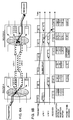
- FIG. 6A represents processing, in which packets successively transmitted from the transmitter arrive at the receiver by way of a router A and a router B.
- the router A and the router B are connected to each other by a plurality of links, and a buffer (queue) for adjusting the sending timing of a packet in accordance with a congestion degree of the links is provided.
- Fig. 6B represents an example with respect to the sending timing at the transmitter and each queue and the reception timing at the receiver.
- the transmitter transmits the packets 1, 2, 3 ⁇ in that order for every certain time period.
- the packets transmitted from the transmitter are received by the receiver by way of either of the link 1 or the link 2.
- the packets arrive at the receiver after being kept waiting for a long time at the queue since the links are congested due to packets for other systems.
- the packet 3 is kept waiting for a long time in the link 1
- the packet 3 is received after the packet 4 and the packet 5 are received by the receiver by way of the link 2.
- the receiver receives the packets 1, 2, 4, 5, 3 and 6 in that order.
- a reception buffer for accumulating a plurality of packets is prepared, and decode processing of voice is applied to a voice frame data first, which is included in not the packet received recently, but the packets received before that. Accordingly, the voice frame data to be decoded becomes available in case that the arrival of the packets is delayed or in case that an arrival order of the packets is replaced.
- a case where the length of the reception buffer is three packets, and the voice decode processing is conducted for every constant time period is shown in Fig. 6B, for example.
- the reception buffer holds three packets received recently, and conducts the voice decode processing for every constant time period using the voice frame data included in the packets in the reception buffer. However, at the timing when a data of the packet 3 is decoded, since the packet 3 does not arrive at the reception buffer, the decode of the packet 3 is conducted by means of interpolation processing using the voice frame data received before that, which is called error concealment processing. Thereafter, the packet 3 is received, and however, since the voice decode processing corresponding to the packet 3 is already conducted, the packet 3 is discarded.
- CELP Code Excited Linear Prediction
- LP linear prediction
- the encoding of the LP analysis and the LP coefficients is conducted for every frame of predetermined length.
- the frame is further divided into sub-frames of predetermined length, and the encoding of the excitation signal is conducted for every sub-frame.
- the excitation signal is constructed of a pitch component representing a pitch period of an input signal, a residual component other than that, and a gain of each component.
- the pitch component is represented by an adaptive code vector stored in a code book for holding the past excitation signal, which is called an adaptive code book.
- the above-described residual component is represented by a signal designed in advance, which is called a voice source code vector.
- a multi-pulse signal consisting of a plurality pulses, and a random number signal or the like are used.
- the information of the voice source code vector is accumulated in a voice source code book.
- an excitation signal calculated from the above-described decoded pitch component and the above-described decoded residual signal is input to the synthesis filter constructed of the above-described decoded LP coefficients to calculate a decoded voice signal.
- a packet is input to a packet input terminal 5 and is transferred to a reception buffer circuit 10.
- the reception buffer circuit 10 receives the packet from the packet input terminal 5, and accumulates predetermined N latest packets.
- N the number of voice frame data included in one packet
- frame length L (msec)
- a communication delay time period due to the reception buffer is N x M x L (msec).
- L is about between 10 and 30 (msec)
- M x N is set about between 2 and 10 in accordance with a delay time period allowed by a communication system to be developed.
- the accumulated packets are rearranged in order of generation time, and are successively transferred to a loss detection circuit 25 and a code division circuit 35.
- the loss detection circuit 25 determines whether or not packet loss exists by using the generation time attached to the packets successively transferred from the reception buffer circuit 10. In case that the generation time is behind time when the packet should be decoded, it is regarded as the loss of the packet.
- the voice decode processing with respect to the packet that is considered to be lost is conducted using the information extracted from the packets received before that. Also, a result of the determination on whether or not the packet loss exists is transferred to a voice source signal circuit 49, a pitch filter circuit 50 and a synthesis circuit 65.
- a reverse packeting circuit 20 extracts a voice frame data from the packets transferred from the reception buffer circuit 10, and transfers it to the code division circuit 35.
- the code division circuit 35 transfers a code of a voice source signal, a code of a pitch filter and a code of a synthesis filter which are obtained by dividing the voice frame data transferred from the reverse packeting circuit 20 to the voice source signal circuit 49, the pitch filter circuit 50 and the synthesis circuit 65, respectively.
- the voice source gain gr is scalar-quantized, and in a quantization table designed in advance, a value corresponding to the transferred codes is assumed to be a decoded value.
- the voice source code vector Cr in the voice source code book prepared in advance, a vector corresponding to the transferred codes is assumed to be a decoded vector.
- the voice source gain and the voice source code vector are created by repeatedly using the voice frame data transferred just before from the code division circuit 35. A random number signal can be substituted for the voice source code vector. An unusual deterioration can be avoided by using the voice source gain after it is reduced by several dB.
- the pitch filter circuit 50 and an excitation signal buffer circuit 54 constitute a filter having the feedback for making an output recur, and in the excitation signal buffer circuit 54, an excitation signal that is a memory value of the filter is accumulated.
- the pitch filter circuit 50 decodes a pitch period L and a pitch gain ga from the codes transferred from the code division circuit 35.
- the pitch period and the pitch gain are scalar-quantized, respectively, and in quantization tables designed in advance, respectively, values corresponding to the transferred codes are assumed to be coded values.
- an adaptive code vector Ca is created by going back to the past by L and cutting the past excitation signals transferred from the excitation signal buffer circuit 54.
- the pitch period and the pitch gain are created by repeatedly using the voice frame data transferred just before from the code division circuit 35. An allophone can be avoided by using the pitch gain after it is reduced by several dB.
- the excitation signal buffer circuit 54 accumulates the excitation signal E transferred from the pitch filter circuit 50 until a predetermined time period in the past, and transfers the accumulated excitation signal to the pitch filter circuit 50.
- the synthesis circuit 65 and a decoded signal buffer circuit 74 constitute a filter having the feedback for making an output recur, and in the decoded signal buffer circuit 74, a decoded signal that is a memory value of the filter is accumulated.
- p is an order of the LP coefficients.
- the LP coefficients are created by repeatedly using the voice frame data transferred just before from the code division circuit 35.
- LSP line spectral pairs
- decoded signal time series x(t) are calculated from excitation signal time series e(t) in accordance with the following equation:
- the decoded signal buffer circuit 74 transfers the decoded signals accumulated only at p time in the past, out of the decoded signals transferred from the synthesis circuit 65, to the synthesis circuit 65.
- the decoded voice output terminal 80 outputs the decoded voice transferred from the synthesis circuit 65.
- a filter for enhancing a spectrum peak which is called a post filter
- a post filter a filter for enhancing a spectrum peak
- a voice signal is input to a voice input terminal 100, and is transferred to a frame circuit 105.
- the frame circuit 105 cuts decoded signals transferred from the voice input terminal 100 by predetermined frame length, and transfers them to an LP analysis circuit 115, a pitch period candidate selection circuit 120 and a sub-frame circuit 110.
- the sub-frame circuit 110 divides the signal transferred from the frame circuit 105 into predetermined sub-frame length, and transfers it to an excitation signal encoding circuit 130.
- the LP analysis circuit 115 conducts an LP analysis of the signal transferred from the frame circuit 105 to obtain LP coefficients. Next, these LP coefficients are transferred to an LP coefficient encoding circuit 125 and the pitch period candidate selection circuit 120.
- the LP coefficient encoding circuit 125 applies vector-quantization to the LP coefficients transferred from the LP analysis circuit 115, and transfers the codes thereof to a code combination circuit 140.
- the Literature (4) can be referred to.
- the quantized LP coefficients are transferred to the excitation signal encoding circuit 130.
- the pitch period candidate selection circuit 120 selects a candidate of a pitch period by using the decoded signals transferred from the frame circuit 105, and transfers it to the excitation signal encoding circuit 130.
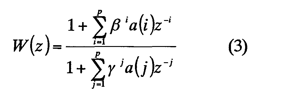
- ⁇ and ⁇ are coefficients for adjusting a weighting degree for improving auditory voice quality, and take values which meet 0 ⁇ 1.
- an auto-correlation function of these weighted decoded signals is calculated in a range between 20 and 147 of a correlation lag, and the correlation lag at which the auto-correlation becomes a maximum, and values adjacent thereto are set as the candidates of the pitch period.
- the excitation signal encoding circuit 130 encodes an excited component of a signal vector Sd of the sub-frame length, for every sub-frame, which was transferred from the sub-frame circuit 110, and transfers the code thereof to the code combination circuit 140.
- an adaptive code vector is created by going back to the past by a time period L and cutting the excitation signals decoded in the past by the sub-frame length, which were transferred from the excitation signal buffer circuit 135.
- ga (L) is an optimum pitch gain calculated for every pitch period L.
- ga(L) ⁇ Sdw,Saw (L) ⁇ / ⁇ Saw (L) ⁇
- ⁇ x ⁇ and ⁇ x,y ⁇ mean a norm of a vector x, and an inner product of a vector x and a vector y, respectively.
- codes obtained by applying scalar-quantization to Lo and ga (Lo) are transferred to the code combination circuit 140. Further, by subtracting a vector obtained by multiplying the weighted pitch component vector Saw (Lo) by a quantized optimum pitch gain gaq (Lo) from the weighted decode signal vector Sdw, a residual signal vector Sdw' is obtained. Further, the k-th accumulated voice source vector Cr (k) is taken out from the voice source code book designed in advance. Next, filtering is applied to this voice source code vector by means of the equation (1), and a decoded signal Sr (k) having only a residual component is calculated.
- the decoded signal vector Sd and the residual component vector Sr (k) are weighted, respectively, by using the equation (3) to obtain the weighted decode signal vector Sdw and a weighted residual component vector Srw (k).
- gr (k) is an optimum voice source gain calculated for every delay.
- the code combination circuit 140 gathers the LP coefficients, the codes with respect to the voice source component and the pitch component, which were transferred from the LP coefficient encoding circuit 125 and the excitation signal encoding circuit 130, and transfers them to a packeting circuit 141 as a voice frame data.
- the packeting circuit 141 gathers the predetermined number of the voice frame data transferred from the code combination circuit 140, and generates a packet to which generation time or the like is added, and transfers it to a packet output terminal 40.
- the packet transferred from the packeting circuit 141 is output from the packet output terminal 40.
- the filtering processing is conducted by using the filter memory values generated by the concealment processing, there is a task that voice quality of the decoded signal is deteriorated.
- the reason thereof is that the filter memory values are generated by using the concealment processing in the decoding of the packet for which it was determined that the packet was lost.
- the present invention was created in the light of the above-described task, and the objective thereof is to provide a voice decode apparatus, a voice encoding decode apparatus and a method thereof, in which the deterioration of voice quality of a decoded signal is reduced.
- the first invention for accomplishing the above-described objective is a voice decoding apparatus having means for receiving a packet, means for determining whether or not said packet has been lost, means for conducting first filtering processing using a pitch period decoded from said received packet, and means for conducting second filtering processing using a spectrum envelope decoded from said packet, characterized in that the apparatus has:
- the second invention for accomplishing the above-described objective is a voice decode apparatus having means for receiving a packet, means for determining whether or not said packet has been lost, and means for conducting filtering processing using a spectrum envelope decoded from said received packet, characterized in that the apparatus has:
- the third invention for accomplishing the above-described objective is a voice decoding apparatus having means for receiving a packet, means for determining whether or not said packet has been lost, means for conducting first filtering processing using a pitch period decoded from said received packet, and means for conducting second filtering processing using a spectrum envelope decoded from said packet, characterized in that the apparatus has:
- the fourth invention for accomplishing the above-described objective is a voice decoding apparatus in any of the above-described first, second and third inventions, characterized in that the apparatus further has means for requesting resending of the packet which has been lost in case that it has been determined to be lost at said determination means.
- the fifth invention for accomplishing the above-described objective is a voice encoding apparatus characterized in that the apparatus has means for resending a packet which has been lost in accordance with a request of the resending of said packet.
- a voice code decoding apparatus which has a voice decode apparatus in any of the above-described first, second and third inventions, further having means for requesting resending of the packet which has been lost in case that it has been determined to be lost at said determination means, and a voice encoding device having means for resending a packet which has been lost in accordance with a request of the resending of said packet.
- the sixth invention for accomplishing the above-described objective is a voice decoding method having a step of receiving a packet, a step of determining whether or not said packet has been lost, a step of conducting first filtering processing using a pitch period decoded from said received packet, and a step of conducting second filtering processing using a spectrum envelope decoded from said packet, characterized in that the method has:
- the seventh invention for accomplishing the above-described objective is a voice decoding method having a step of receiving a packet, a step of determining whether or not said packet has been lost, and a step of conducting filtering processing using a spectrum envelope decoded from said packet, characterized in that the method has:
- the eighth invention for accomplishing the above-described objective is a voice decoding method having a step of receiving a packet, a step of determining whether or not said packet has been lost, a step of conducting first filtering processing using a pitch period decoded from said received packet, and a step of conducting second filtering processing using a spectrum envelope decoded from said packet, characterized in that the method has:
- the ninth invention for accomplishing the above-described objective is a voice decoding method in any of the above-described sixth, seventh and eighth inventions, characterized in that the method further has a step of requesting resending of the packet which has been lost in case that it has been determined to be lost at said determination means.
- the tenth invention for accomplishing the above-described objective is a voice encoding method characterized in that the method has a step of resending a packet which has been lost in accordance with a request of the resending of said packet.
- the method has a step of resending a packet, which has been lost in accordance with a request of the resending of said packet.
- a decoded signal and a filter memory value are calculated at that time by using an appropriate signal by means of the concealment processing.
- the filter memory value is recalculated for frames to be decoded from that time to the present. Accordingly, it becomes possible to remove an effect of the deterioration by the concealment processing in the filter memory value.
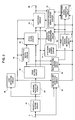
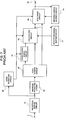
- Fig. 1 is a block diagram showing a structure of a voice decode apparatus in a first embodiment based on the present invention.
- the first embodiment is characterized in that a past excitation signal that is a filter memory value to be used in a pitch filter is updated by using a voice frame data included in a packet that was received late.
- a packet is input to the packet input terminal 5, and is transferred to the reception buffer circuit 10 and the reuse packet detection circuit 30.
- the reception buffer circuit 10 receives the packet from the packet input terminal 5, and accumulates predetermined N updated packets.
- the accumulated packets are rearranged in order of generation time, and are successively transferred to the loss detection circuit 25, the reuse packet detection circuit 30 and the code division circuit 35.
- the loss detection circuit 25 determines whether or not packet loss exists by using the generation time attached to the packets successively transferred from the reception buffer circuit 10. Also, a result of the determination is transferred to the voice source signal circuit 49, the pitch filter circuit 50, the synthesis circuit 65 and the reuse packet detection circuit 30.
- the code division circuit 35 transfers a code of a voice source signal and a code of a pitch filter, which were obtained by dividing a voice frame data transferred from the reverse packeting circuit 20, to the voice source signal circuit 49 and the excitation code buffer circuit 40, and transfers a code of a synthesis filter to the synthesis circuit 65.
- the reuse packet detection circuit 30 obtains the generation time of the loss packet from the packet transferred from the reception buffer circuit 10 and records it. Next, in case that the recorded generation time coincides with the generation time of the packet transferred from the packet input terminal 5, a command for recalculating excitation signals is transferred to the excitation code buffer circuit 40, the past excitation signal generation circuit 60 and the updated excitation signal buffer circuit 55, together with the generation time of the loss packet which arrived late.
- the excitation code buffer circuit 40 accumulates the voice source signal and the codes of the pitch filter, which were transferred from the code division circuit 35, until the past for a time period corresponding to the predetermined number of packets.
- the excitation code buffer circuit 40 transfers the codes being accumulated after the transferred loss packet generation time to the past excitation signal generation circuit 60.
- the past excitation signal generation circuit 60 When receiving the recalculation command of the excitation signals from the reuse packet detection circuit 30, by using the codes of the excitation signals, which were transferred from the excitation code buffer circuit 40, the past excitation signal generation circuit 60 conducts the decode processing of the excitation signals up to a frame prior to a frame being presently processed from a retroactive frame, packet of which was lost.
- the decode processing is the same as one conducted by the voice source signal circuit 49, the pitch filter circuit 50 and the excitation signal buffer 54.
- the quantity of operation becomes times as much as the frame number from the frame, packet of which was lost, to the frame being presently processed. The quantity of operation depends on the number of the packets, which are retroactively detected in the reuse packet detection.
- the excitation signals recalculated up to the prior frame are transferred to the updated excitation signal buffer circuit 55.
- the updated excitation signal buffer circuit 55 accumulates the excitation signals E transferred from the pitch filter circuit 50 for a predetermined time period in the past, and transfers the accumulated excitation signals to the pitch filter circuit 50.
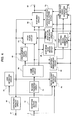
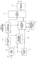
- Fig. 2 is a block diagram showing a structure of a voice decode apparatus in the second embodiment based on the present invention.
- the second embodiment is characterized in that a filter memory value to be used in a filter representing a spectrum envelope is updated by using a voice frame data included in a packet that was received late.
- the points different from the first embodiment of the voice decoding apparatus are:
- a difference of the reuse packet detection circuit 30 in the second embodiment from the reuse packet detection circuit 30 in the first embodiment is that, in case that the packet transferred from the packet input terminal 5 coincides with the recorded generation time, the command for recalculating the excitation signals and the loss frame generation time are also transferred to the past decoded signal generation circuit 70 and the updated decoded signal buffer circuit 75 when being transferred from the packet input terminal 5.
- a difference of the code division circuit 35 in the second embodiment from the reuse packet detection circuit 30 in the first embodiment is that the codes of the synthesis filter are also transferred to the synthesis code buffer circuit 45.
- a difference of the pitch filter circuit 50 in the second embodiment from the pitch filter circuit 60 in the first embodiment is that the transfer and reception of the excitation signals are conducted to and from the excitation signal buffer circuit 54, not to and from the updated excitation signal buffer 55.
- a difference of the synthesis circuit 65 in the second embodiment from the synthesis circuit 65 in the first embodiment is that the transfer and reception of the decoded signals are conducted to and from the updated decoded signal buffer circuit 75, not to and from the decoded signal buffer circuit 74.
- the excitation signal buffer circuit 54 accumulates the excitation signals E transferred from the pitch filter circuit 50 until the past for a predetermined time period, and transfers the accumulated excitation signals to the pitch filter circuit 50.
- the synthesis code buffer circuit 45 accumulates the codes of the LP coefficients representing a spectrum envelope transferred from the code division circuit 35 until the past for a time period corresponding to a predetermined number of packets. In order to use packets, which are received late, it is required that the number of these packets is longer than reception buffer length. Also, when a recalculation command of the LP filter codes is received from the reuse packet detection circuit 30, the codes accumulated after the generation time of the transferred loss packet are transferred to the past decoded signal generation circuit 70.
- the past decoded signal generation circuit 70 When receiving the recalculation command of the excitation signals from the reuse packet detection circuit 30, by using the codes of the LP coefficients, which were transferred from the synthesis code buffer circuit 45, and the excitation signals transferred from the past excitation signal generation circuit 60, the past decoded signal generation circuit 70 conducts the decode processing up to a frame prior to a frame being presently processed from a retroactive frame included in the loss packet.
- the decode processing is the same as one conducted in the synthesis circuit 65. In the frame in which this processing is conducted, with regard to the generation of the excitation signals, the quantity of operation becomes times as much as the frame number from the frame corresponding to the loss packet to the frame being presently processed. The quantity of operation depends on the number of the packets which are retroactively detected in the reuse packet detection.
- the decoded signals recalculated up to the prior frame are transferred to the updated decoded signal buffer circuit 75.
- the updated decoded signal buffer circuit 75 accumulates the decoded signals transferred from the synthesis circuit 65, and transfers the decoded signals accumulated at p time in the past to the synthesis circuit 65. In case that the recalculation command of the decoded signals is transferred from the reuse packet detection circuit 30, after the decoded signals being already accumulated are replaced with the decoded signals recalculated by the past decoded signal generation circuit 70, these decoded signals are transferred to the synthesis circuit 65.
- Fig. 3 is a block diagram showing a structure of a voice decode apparatus in the third embodiment based on the present invention.
- the third embodiment is characterized in that both a filter memory value to be used in a filter representing a pitch and a filter memory value to be used in a filter representing a spectrum envelope are updated by using a voice frame data included in a packet that was received late.
- a filter memory value to be used in a filter representing a pitch and a filter memory value to be used in a filter representing a spectrum envelope are updated by using a voice frame data included in a packet that was received late.
- Fig. 4 is a block diagram showing a structure of a voice decode apparatus in the fourth embodiment based on the present invention.
- the fourth embodiment is characterized in that, in the above-mentioned first, second or third embodiment, means for outputting a signal for requesting the resending of a packet which was lost in case that packet loss occurs is provided.
- the different points of the fourth embodiment from the voice decode apparatus of the third embodiment are:
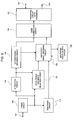
- Fig. 5 is a block diagram showing a structure of a voice encoding apparatus in the fifth embodiment based on the present invention.
- the fifth embodiment relates to a voice encoding apparatus in which a loss packet request output from the voice decode apparatus in accordance with the fourth embodiment is received, and a corresponding packet is resent.
- the different points of the voice encoding apparatus of the fifth embodiment from the voice encoding apparatus of the conventional system are:
- a difference of the code combination circuit 140 of the fifth embodiment from the conventional system is that combined codes are transferred to the packeting circuit with resending 142, not to the packeting circuit 141.
- the loss packet request input terminal 144 receives a loss packet request, and transfers it to the packeting circuit 142 with resending.
- the packeting circuit 142 with resending gathers the predetermined number of the voice frame data transferred from the code combination circuit 140, and generates packets to which generation time or the like is added, and transfers them to the packet output terminal 40. Also, the above-described packets are accumulated until the predetermined past. Further, when the loss packet request is transferred from the loss packet request input terminal 144, the requested packet is taken out from the above-described accumulated packets, and is transferred to the packet output terminal 145.
- the packet transferred from the packeting circuit 142 with resending is output from the packet output terminal 145.
- the filter memory value which is not affected by the loss of the packet is used for the calculation, an excellent advantage that the voice quality deterioration of the decoded signals can be reduced is effected.
- the reason thereof is that the filter memory value is generated by the decode processing using the received packet, not by the concealment processing.
- a reuse packet detection circuit 30 obtains the generation time of loss packet from the packet transferred from a reception buffer circuit 10 and records it. Next, in case that the recorded generation time coincides with the generation time of the packet transferred from a packet input terminal 5, a command for recalculating excitation signals is transferred to an excitation code buffer circuit 40, a past excitation signal generation circuit 60 and an updated excitation signal buffer circuit 55, together with the generation time of the loss packet which arrived late.
- the excitation code buffer circuit 40 accumulates the voice source signal and the codes of a pitch filter, which were transferred from a code division circuit 35, until the past for a time period corresponding to the predetermined number of packets.
- the excitation code buffer circuit 40 transfers the codes being accumulated after the transferred loss packet generation time to a past excitation generation circuit 60.
- the past excitation signal generation circuit 60 conducts the decode processing of the excitation signals up to a frame prior to a frame being presently processed from a retroactive frame, packet of which was lost.
- the decode processing is the same as one conducted by a voice source signal circuit 49, a pitch filter circuit 50 and an excitation signal buffer 54.
- the quantity of operation becomes times as much as the frame number from the frame, packet of which was lost, to the frame being presently processed. The quantity of operation depends on the number of the packets which are retroactively detected in the reuse packet detection.
- the excitation signals recalculated up to the prior frame are transferred to an updated excitation signal buffer circuit 55.
- the updated excitation signal buffer circuit 55 accumulates the excitation signals E transferred from the pitch filter circuit 50 for a predetermined time period in the past, and transfers the accumulated excitation signals to the pitch filter circuit 50.
Landscapes
- Engineering & Computer Science (AREA)
- Signal Processing (AREA)
- Computational Linguistics (AREA)
- Health & Medical Sciences (AREA)
- Audiology, Speech & Language Pathology (AREA)
- Human Computer Interaction (AREA)
- Physics & Mathematics (AREA)
- Acoustics & Sound (AREA)
- Multimedia (AREA)
- Computer Networks & Wireless Communication (AREA)
- Data Exchanges In Wide-Area Networks (AREA)
- Detection And Prevention Of Errors In Transmission (AREA)
Abstract
Description


The
characterized in that the apparatus has:
characterized in that the apparatus has:
characterized in that the apparatus further has means for requesting resending of the packet which has been lost in case that it has been determined to be lost at said determination means.
The excitation
A difference of the
Claims (18)
- A voice decode apparatus having means for receiving a packet, means for determining whether or not said packet has been lost, means for conducting first filtering processing using a pitch period decoded from said received packet, and means for conducting second filtering processing using a spectrum envelope decoded from said packet, said apparatus comprising:means for detecting that the packet which has been determined to be lost at said determination means is delayed and received,means for accumulating information in relation to said first filtering processing; andmeans for calculating a filter memory value to be used for said first filtering processing when said reception is detected, using said information accumulated before that.
- A voice decode apparatus recited in claim 1, further comprising means for requesting resending of the packet which has been lost in case that it has been determined to be lost at said determination means.
- A voice code decoding/encoding apparatus having means for receiving a packet, means for determining whether or not said packet has been lost, means for conducting first filtering processing using a pitch period decoded from said received packet, and means for conducting second filtering processing using a spectrum envelope decoded from said packet, said apparatus comprising:means for detecting that the packet which has been determined to be lost at said determination means is delayed and received,means for accumulating information in relation to said first filtering processing;means for calculating a filter memory value to be used for said first filtering processing when said reception is detected, using said information accumulated before that;means for requesting resending of the packet which has been lost in case that it has been determined to be lost at said determination means; andmeans for resending a packet which has been lost in accordance with a request of the resending of packet.
- A voice decode apparatus having means for receiving a packet, means for determining whether or not said packet has been lost, and means for conducting filtering processing using a spectrum envelope decoded from said received packet, said apparatus comprising:means for detecting that the packet which has been determined to be lost at said determination means is delayed and received,means for accumulating information in relation to said filtering processing; andmeans for calculating a filter memory value to be used for said filtering processing when said reception is detected, using said information accumulated before that.
- A voice decode apparatus recited in claim 2, further comprising means for requesting resending of the packet which has been lost in case that it has been determined to be lost at said determination means.
- A voice code decoding/encoding apparatus having means for receiving a packet, means for determining whether or not said packet has been lost, and means for conducting filtering processing using a spectrum. envelope decoded from said received packet, said apparatus comprising:means for detecting that the packet which has been determined to be lost at said determination means is delayed and received,means for accumulating information in relation to said filtering processing;means for calculating a filter memory value to be used for said filtering processing when said reception is detected, using said information accumulated before that;means for requesting resending of the packet which has been lost in case that it has been determined to be lost at said determination means; andmeans for resending a packet which has been lost in accordance with a request of the resending of packet.
- A voice decode apparatus having means for receiving a packet, means for determining whether or not said packet has been lost, means for conducting first filtering processing using a pitch period decoded from said received packet, and means for conducting second filtering processing using a spectrum envelope decoded from said packet, said apparatus comprising:means for detecting that the packet which has been determined to be lost at said determination means is delayed and received,means for accumulating first information in relation to said first filtering processing;.means for accumulating second information in relation to said second filtering processing;means for calculating a filter memory value to be used for said first filtering processing when said reception is detected, using said first information accumulated before that; andmeans for calculating a filter memory value to be used for said second filtering processing when said reception is detected, using said second information accumulated before that.
- A voice decode apparatus recited in claim 7, further comprising means for requesting resending of the packet which has been lost in case that it has been determined to be lost at said determination means.
- A voice code decoding/encoding apparatus having means for receiving a packet, means for determining whether or not said packet has been lost, means for conducting first filtering processing using a pitch period decoded from said received packet, and means for conducting second filtering processing using a spectrum envelope decoded from said packet, said apparatus comprising:means for detecting that the packet which has been determined to be lost at said determination means is delayed and received,means for accumulating first information in relation to said first filtering processing;means for accumulating second information in relation to said second filtering processing;means for calculating a filter memory value to be used for said first filtering processing when said reception is detected, using said first information accumulated before that;means for calculating a filter memory value to be used for said second filtering processing when said reception is detected, using said second information accumulated before that;means for requesting resending of the packet which has been lost in case that it has been determined to be lost at said determination means; andmeans for resending a packet which has been lost in accordance with a request of the resending of packet.
- A voice decoding method having a step of receiving a packet, a step of determining whether or not said packet has been lost, a step of conducting first filtering processing using a pitch period decoded from said received packet, and a step of conducting second filtering processing using a spectrum envelope decoded from said packet, said method comprising:a step of detecting that the packet which has been determined to be lost at said determination step is delayed and received,a step of accumulating information in relation to said first filtering processing; anda step of calculating a filter memory value to be used for said first filtering processing when said reception is detected, using said information accumulated before that.
- A voice decoding method recited in claim 10, further comprising a step of requesting resending of the packet which has been lost in case that it has been determined to be lost at said determination means.
- A voice encoding/decoding method having a step of receiving a packet, a step of determining whether or not said packet has been lost, a step of conducting first filtering processing using a pitch period decoded from said received packet, and a step of conducting second filtering processing using a spectrum envelope decoded from said packet, said method comprising:a step of detecting that the packet which has been determined to be lost at said determination step is delayed and received,a step of accumulating information in relation to said first filtering processing;a step of calculating a filter memory value to be used for said first filtering processing when said reception is detected, using said information accumulated before that;a step of requesting resending of the packet which has been lost in case that it has been determined to be lost at said determination means; anda step of resending a packet which has been lost in accordance with a request of the resending of said packet.
- A voice decoding method having a step of receiving a packet, a step of determining whether or not said packet has been lost, and a step of conducting filtering processing using a spectrum envelope decoded from said packet, said method comprising:a step of detecting that the packet which has been determined to be lost at said determination step is delayed and received,a step of accumulating information in relation to said filtering processing; anda step of calculating a filter memory value to be used for said filtering processing when said reception is detected, using said information accumulated before that.
- A voice decoding method recited in claim 13, further comprising a step of requesting resending of the packet which has been lost in case that it has been determined to be lost at said determination means.
- A voice encoding/decoding method having a step of receiving a packet, a step of determining whether or not said packet has been lost, and a step of conducting filtering processing using a spectrum envelope decoded from said packet, said method comprising:a step of detecting that the packet which has been determined to be lost at said determination step is delayed and received,a step of accumulating information in relation to said filtering processing;a step of calculating a filter memory value to be used for said filtering processing when said reception is detected, using said information accumulated before that;a step of requesting resending of the packet which has been lost in case that it has been determined to be lost at said determination means; anda step of resending a packet which has been lost in accordance with a request of the resending of said packet.
- A voice decoding method having a step of receiving a packet, a step of determining whether or not said packet has been lost, a step of conducting first filtering processing using a pitch period decoded from said received packet, and a step of conducting second filtering processing using a spectrum envelope decoded from said packet, said method comprising:a step of detecting that the packet which has been determined to be lost at said determination step is delayed and received,a step of accumulating first information in relation to said first filtering processing;a step of accumulating second information in relation to said second filtering processing;a step of calculating a filter memory value to be used for said first filtering processing when said reception is detected, using said first information accumulated before that; anda step of calculating a filter memory value to be used for said second filtering processing when said reception is detected, using said second information accumulated before that.
- A voice decoding method recited in claim 16, further comprising a step of requesting resending of the packet which has been lost in case that it has been determined to be lost at said determination means.
- A voice encoding/decoding method having a step of receiving a packet, a step of determining whether or not said packet has been lost, a step of conducting first filtering processing using a pitch period decoded from said received packet, and a step of conducting second filtering processing using a spectrum envelope decoded from said packet, said method comprising:a step of detecting that the packet which has been determined to be lost at said determination step is delayed and received,a step of accumulating first information in relation to said first filtering processing;a step of accumulating second information in relation to said second filtering processing;a step of calculating a filter memory value to be used for said first filtering processing when said reception is detected, using said first information accumulated before that;a step of calculating a filter memory value to be used for said second filtering processing when said reception is detected, using said second information accumulated before that;a step of requesting resending of the packet which has been lost in case that it has been determined to be lost at said determination means; anda step of resending a packet which has been lost in accordance with a request of the resending of said packet.
Applications Claiming Priority (2)
| Application Number | Priority Date | Filing Date | Title |
|---|---|---|---|
| JP2001069795 | 2001-03-13 | ||
| JP2001069795A JP2002268697A (en) | 2001-03-13 | 2001-03-13 | Voice decoder tolerant for packet error, voice coding and decoding device and its method |
Publications (3)
| Publication Number | Publication Date |
|---|---|
| EP1241664A2 true EP1241664A2 (en) | 2002-09-18 |
| EP1241664A3 EP1241664A3 (en) | 2003-12-03 |
| EP1241664B1 EP1241664B1 (en) | 2006-08-30 |
Family
ID=18927781
Family Applications (1)
| Application Number | Title | Priority Date | Filing Date |
|---|---|---|---|
| EP02005778A Expired - Lifetime EP1241664B1 (en) | 2001-03-13 | 2002-03-13 | Voice encoding/decoding apparatus with packet error resistance and method thereof |
Country Status (6)
| Country | Link |
|---|---|
| US (1) | US20020169859A1 (en) |
| EP (1) | EP1241664B1 (en) |
| JP (1) | JP2002268697A (en) |
| AT (1) | ATE338332T1 (en) |
| CA (1) | CA2374725A1 (en) |
| DE (1) | DE60214265T2 (en) |
Cited By (2)
| Publication number | Priority date | Publication date | Assignee | Title |
|---|---|---|---|---|
| RU2407175C2 (en) * | 2004-11-03 | 2010-12-20 | Вераз Нетворкс Лтд. | Methods of providing security in packet switched communication networks and device for realising said methods |
| WO2012130297A1 (en) * | 2011-03-30 | 2012-10-04 | Phonak Ag | Wireless sound transmission system and method |
Families Citing this family (17)
| Publication number | Priority date | Publication date | Assignee | Title |
|---|---|---|---|---|
| JP4304360B2 (en) * | 2002-05-22 | 2009-07-29 | 日本電気株式会社 | Code conversion method and apparatus between speech coding and decoding methods and storage medium thereof |
| JP4365653B2 (en) | 2003-09-17 | 2009-11-18 | パナソニック株式会社 | Audio signal transmission apparatus, audio signal transmission system, and audio signal transmission method |
| WO2005109401A1 (en) * | 2004-05-10 | 2005-11-17 | Nippon Telegraph And Telephone Corporation | Acoustic signal packet communication method, transmission method, reception method, and device and program thereof |
| IL163092A (en) | 2004-07-19 | 2010-11-30 | Veraz Networks Ltd | Processing of packets forwarded in communication networks |
| US7783482B2 (en) * | 2004-09-24 | 2010-08-24 | Alcatel-Lucent Usa Inc. | Method and apparatus for enhancing voice intelligibility in voice-over-IP network applications with late arriving packets |
| JP4678440B2 (en) | 2006-07-27 | 2011-04-27 | 日本電気株式会社 | Audio data decoding device |
| JP5056049B2 (en) * | 2007-02-16 | 2012-10-24 | 日本電気株式会社 | Audio data decoding device |
| US8768383B2 (en) | 2007-09-13 | 2014-07-01 | Lg Electronics Inc. | Method for providing control information using the paging procedure |
| KR101441138B1 (en) | 2007-09-28 | 2014-09-18 | 엘지전자 주식회사 | A method for performing uplink time synchronization in a wireless communication system |
| KR101428816B1 (en) | 2007-09-28 | 2014-08-12 | 엘지전자 주식회사 | Method for reselecting a cell and detecting whether a terminal is stationay in mobile telecommunications system |
| CN101828344B (en) * | 2007-10-17 | 2012-12-05 | Lg电子株式会社 | Method of providing circuit switched (CS) service using high-speed downlink packet access (HSDPA) or high-speed uplink packet access (HSDPA) |
| KR101473010B1 (en) | 2007-10-17 | 2014-12-15 | 엘지전자 주식회사 | How to provide circuit services using packet network |
| KR101532789B1 (en) | 2008-01-04 | 2015-07-09 | 엘지전자 주식회사 | HARQ operation method for processing retransmission data |
| KR101514079B1 (en) | 2008-01-07 | 2015-04-21 | 엘지전자 주식회사 | Reconfiguration method of uplink time synchronization timer |
| US8898053B2 (en) | 2009-05-22 | 2014-11-25 | Panasonic Intellectual Property Corporation Of America | Encoding device, decoding device, and methods therein |
| JP5400880B2 (en) * | 2009-06-23 | 2014-01-29 | 日本電信電話株式会社 | Encoding method, decoding method, apparatus, program, and recording medium using those methods |
| IL200694A (en) | 2009-09-02 | 2014-04-30 | Gil Levy | Method and device for forwarding frames in a communications network |
Family Cites Families (12)
| Publication number | Priority date | Publication date | Assignee | Title |
|---|---|---|---|---|
| US5125030A (en) * | 1987-04-13 | 1992-06-23 | Kokusai Denshin Denwa Co., Ltd. | Speech signal coding/decoding system based on the type of speech signal |
| US5450449A (en) * | 1994-03-14 | 1995-09-12 | At&T Ipm Corp. | Linear prediction coefficient generation during frame erasure or packet loss |
| US5574825A (en) * | 1994-03-14 | 1996-11-12 | Lucent Technologies Inc. | Linear prediction coefficient generation during frame erasure or packet loss |
| US5875292A (en) * | 1995-02-10 | 1999-02-23 | Nec Corporation | Packet transmission method without sending serial numbers |
| US5699485A (en) * | 1995-06-07 | 1997-12-16 | Lucent Technologies Inc. | Pitch delay modification during frame erasures |
| US5907822A (en) * | 1997-04-04 | 1999-05-25 | Lincom Corporation | Loss tolerant speech decoder for telecommunications |
| IL120788A (en) * | 1997-05-06 | 2000-07-16 | Audiocodes Ltd | Systems and methods for encoding and decoding speech for lossy transmission networks |
| SE513520C2 (en) * | 1998-05-14 | 2000-09-25 | Ericsson Telefon Ab L M | Method and apparatus for masking delayed packages |
| US6810377B1 (en) * | 1998-06-19 | 2004-10-26 | Comsat Corporation | Lost frame recovery techniques for parametric, LPC-based speech coding systems |
| US6260009B1 (en) * | 1999-02-12 | 2001-07-10 | Qualcomm Incorporated | CELP-based to CELP-based vocoder packet translation |
| US6973425B1 (en) * | 1999-04-19 | 2005-12-06 | At&T Corp. | Method and apparatus for performing packet loss or Frame Erasure Concealment |
| US6975629B2 (en) * | 2000-03-22 | 2005-12-13 | Texas Instruments Incorporated | Processing packets based on deadline intervals |
-
2001
- 2001-03-13 JP JP2001069795A patent/JP2002268697A/en active Pending
-
2002
- 2002-03-06 CA CA002374725A patent/CA2374725A1/en not_active Abandoned
- 2002-03-11 US US10/093,497 patent/US20020169859A1/en not_active Abandoned
- 2002-03-13 DE DE60214265T patent/DE60214265T2/en not_active Expired - Fee Related
- 2002-03-13 EP EP02005778A patent/EP1241664B1/en not_active Expired - Lifetime
- 2002-03-13 AT AT02005778T patent/ATE338332T1/en not_active IP Right Cessation
Cited By (7)
| Publication number | Priority date | Publication date | Assignee | Title |
|---|---|---|---|---|
| RU2407175C2 (en) * | 2004-11-03 | 2010-12-20 | Вераз Нетворкс Лтд. | Methods of providing security in packet switched communication networks and device for realising said methods |
| WO2012130297A1 (en) * | 2011-03-30 | 2012-10-04 | Phonak Ag | Wireless sound transmission system and method |
| CN103563400A (en) * | 2011-03-30 | 2014-02-05 | 峰力公司 | Wireless sound transmission system and method |
| EP2692152B1 (en) * | 2011-03-30 | 2016-07-13 | Sonova AG | Wireless sound transmission system and method |
| CN103563400B (en) * | 2011-03-30 | 2017-02-15 | 索诺瓦公司 | Wireless sound transmission system and method |
| US9681236B2 (en) | 2011-03-30 | 2017-06-13 | Sonova Ag | Wireless sound transmission system and method |
| US9826321B2 (en) | 2011-03-30 | 2017-11-21 | Sonova Ag | Wireless sound transmission system and method |
Also Published As
| Publication number | Publication date |
|---|---|
| US20020169859A1 (en) | 2002-11-14 |
| JP2002268697A (en) | 2002-09-20 |
| DE60214265T2 (en) | 2007-04-05 |
| ATE338332T1 (en) | 2006-09-15 |
| EP1241664B1 (en) | 2006-08-30 |
| CA2374725A1 (en) | 2002-09-06 |
| EP1241664A3 (en) | 2003-12-03 |
| DE60214265D1 (en) | 2006-10-12 |
Similar Documents
| Publication | Publication Date | Title |
|---|---|---|
| EP1241664B1 (en) | Voice encoding/decoding apparatus with packet error resistance and method thereof | |
| EP1288913B1 (en) | Speech transcoding method and apparatus | |
| US20020077812A1 (en) | Voice code conversion apparatus | |
| US20090248404A1 (en) | Lost frame compensating method, audio encoding apparatus and audio decoding apparatus | |
| KR100935174B1 (en) | Fast Code-Vector Navigation Apparatus and Method | |
| JP4215448B2 (en) | Speech decoding apparatus and speech decoding method | |
| JP4473869B2 (en) | Acoustic signal packet communication method, transmission method, reception method, apparatus and program thereof | |
| CA2408890C (en) | System and methods for concealing errors in data transmission | |
| US6871175B2 (en) | Voice encoding apparatus and method therefor | |
| US20110040557A1 (en) | Transmitter and receiver for speech coding and decoding by using additional bit allocation method | |
| CA2293165A1 (en) | Method for transmitting data in wireless speech channels | |
| JP3063668B2 (en) | Voice encoding device and decoding device | |
| Montminy et al. | Improving the performance of ITU-T G. 729A for VoIP | |
| KR100594599B1 (en) | Receiver based packet loss recovery apparatus and method | |
| CN1929355B (en) | Restoring system and method for voice package losing | |
| US20040138878A1 (en) | Method for estimating a codec parameter | |
| US7693151B2 (en) | Method and devices for providing protection in packet switched communications networks | |
| KR20050027272A (en) | Speech communication unit and method for error mitigation of speech frames | |
| JP2002196795A (en) | Audio decoding device and audio encoding / decoding device | |
| JP4060317B2 (en) | Bidirectional communication system, communication device, and communication control method | |
| US20050240400A1 (en) | Method and apparatus for transcoding between different speech encoding/ decoding systems and recording medium | |
| JPH09134198A (en) | Voice decoding device | |
| US20050185678A1 (en) | Interactive communication system, communication equipment and communication control method | |
| EP1536413A1 (en) | Method and device for code conversion between voice encoding and decoding methods and storage medium thereof | |
| EP1739917A1 (en) | Terminal, system and method for discarding encoded parts of a sampled audio stream |
Legal Events
| Date | Code | Title | Description |
|---|---|---|---|
| PUAI | Public reference made under article 153(3) epc to a published international application that has entered the european phase |
Free format text: ORIGINAL CODE: 0009012 |
|
| AK | Designated contracting states |
Kind code of ref document: A2 Designated state(s): AT BE CH CY DE DK ES FI FR GB GR IE IT LI LU MC NL PT SE TR |
|
| AX | Request for extension of the european patent |
Free format text: AL;LT;LV;MK;RO;SI |
|
| PUAL | Search report despatched |
Free format text: ORIGINAL CODE: 0009013 |
|
| AK | Designated contracting states |
Kind code of ref document: A3 Designated state(s): AT BE CH CY DE DK ES FI FR GB GR IE IT LI LU MC NL PT SE TR |
|
| AX | Request for extension of the european patent |
Extension state: AL LT LV MK RO SI |
|
| RIC1 | Information provided on ipc code assigned before grant |
Ipc: 7G 10L 19/00 B Ipc: 7G 10L 19/06 A |
|
| 17P | Request for examination filed |
Effective date: 20040420 |
|
| AKX | Designation fees paid |
Designated state(s): AT BE CH CY DE DK ES FI FR GB GR IE IT LI LU MC NL PT SE TR |
|
| 17Q | First examination report despatched |
Effective date: 20050701 |
|
| GRAP | Despatch of communication of intention to grant a patent |
Free format text: ORIGINAL CODE: EPIDOSNIGR1 |
|
| GRAS | Grant fee paid |
Free format text: ORIGINAL CODE: EPIDOSNIGR3 |
|
| GRAA | (expected) grant |
Free format text: ORIGINAL CODE: 0009210 |
|
| AK | Designated contracting states |
Kind code of ref document: B1 Designated state(s): AT BE CH CY DE DK ES FI FR GB GR IE IT LI LU MC NL PT SE TR |
|
| PG25 | Lapsed in a contracting state [announced via postgrant information from national office to epo] |
Ref country code: IT Free format text: LAPSE BECAUSE OF FAILURE TO SUBMIT A TRANSLATION OF THE DESCRIPTION OR TO PAY THE FEE WITHIN THE PRESCRIBED TIME-LIMIT;WARNING: LAPSES OF ITALIAN PATENTS WITH EFFECTIVE DATE BEFORE 2007 MAY HAVE OCCURRED AT ANY TIME BEFORE 2007. THE CORRECT EFFECTIVE DATE MAY BE DIFFERENT FROM THE ONE RECORDED. Effective date: 20060830 Ref country code: CH Free format text: LAPSE BECAUSE OF FAILURE TO SUBMIT A TRANSLATION OF THE DESCRIPTION OR TO PAY THE FEE WITHIN THE PRESCRIBED TIME-LIMIT Effective date: 20060830 Ref country code: AT Free format text: LAPSE BECAUSE OF FAILURE TO SUBMIT A TRANSLATION OF THE DESCRIPTION OR TO PAY THE FEE WITHIN THE PRESCRIBED TIME-LIMIT Effective date: 20060830 Ref country code: FI Free format text: LAPSE BECAUSE OF FAILURE TO SUBMIT A TRANSLATION OF THE DESCRIPTION OR TO PAY THE FEE WITHIN THE PRESCRIBED TIME-LIMIT Effective date: 20060830 Ref country code: NL Free format text: LAPSE BECAUSE OF FAILURE TO SUBMIT A TRANSLATION OF THE DESCRIPTION OR TO PAY THE FEE WITHIN THE PRESCRIBED TIME-LIMIT Effective date: 20060830 Ref country code: BE Free format text: LAPSE BECAUSE OF FAILURE TO SUBMIT A TRANSLATION OF THE DESCRIPTION OR TO PAY THE FEE WITHIN THE PRESCRIBED TIME-LIMIT Effective date: 20060830 Ref country code: LI Free format text: LAPSE BECAUSE OF FAILURE TO SUBMIT A TRANSLATION OF THE DESCRIPTION OR TO PAY THE FEE WITHIN THE PRESCRIBED TIME-LIMIT Effective date: 20060830 |
|
| REG | Reference to a national code |
Ref country code: GB Ref legal event code: FG4D |
|
| REG | Reference to a national code |
Ref country code: CH Ref legal event code: EP |
|
| REG | Reference to a national code |
Ref country code: IE Ref legal event code: FG4D |
|
| REF | Corresponds to: |
Ref document number: 60214265 Country of ref document: DE Date of ref document: 20061012 Kind code of ref document: P |
|
| PG25 | Lapsed in a contracting state [announced via postgrant information from national office to epo] |
Ref country code: SE Free format text: LAPSE BECAUSE OF FAILURE TO SUBMIT A TRANSLATION OF THE DESCRIPTION OR TO PAY THE FEE WITHIN THE PRESCRIBED TIME-LIMIT Effective date: 20061130 Ref country code: DK Free format text: LAPSE BECAUSE OF FAILURE TO SUBMIT A TRANSLATION OF THE DESCRIPTION OR TO PAY THE FEE WITHIN THE PRESCRIBED TIME-LIMIT Effective date: 20061130 |
|
| PG25 | Lapsed in a contracting state [announced via postgrant information from national office to epo] |
Ref country code: ES Free format text: LAPSE BECAUSE OF FAILURE TO SUBMIT A TRANSLATION OF THE DESCRIPTION OR TO PAY THE FEE WITHIN THE PRESCRIBED TIME-LIMIT Effective date: 20061211 |
|
| PG25 | Lapsed in a contracting state [announced via postgrant information from national office to epo] |
Ref country code: PT Free format text: LAPSE BECAUSE OF FAILURE TO SUBMIT A TRANSLATION OF THE DESCRIPTION OR TO PAY THE FEE WITHIN THE PRESCRIBED TIME-LIMIT Effective date: 20070212 |
|
| REG | Reference to a national code |
Ref country code: CH Ref legal event code: PL |
|
| NLV1 | Nl: lapsed or annulled due to failure to fulfill the requirements of art. 29p and 29m of the patents act | ||
| ET | Fr: translation filed | ||
| PLBE | No opposition filed within time limit |
Free format text: ORIGINAL CODE: 0009261 |
|
| STAA | Information on the status of an ep patent application or granted ep patent |
Free format text: STATUS: NO OPPOSITION FILED WITHIN TIME LIMIT |
|
| 26N | No opposition filed |
Effective date: 20070531 |
|
| PG25 | Lapsed in a contracting state [announced via postgrant information from national office to epo] |
Ref country code: IE Free format text: LAPSE BECAUSE OF NON-PAYMENT OF DUE FEES Effective date: 20070313 Ref country code: MC Free format text: LAPSE BECAUSE OF NON-PAYMENT OF DUE FEES Effective date: 20070331 |
|
| PG25 | Lapsed in a contracting state [announced via postgrant information from national office to epo] |
Ref country code: GR Free format text: LAPSE BECAUSE OF FAILURE TO SUBMIT A TRANSLATION OF THE DESCRIPTION OR TO PAY THE FEE WITHIN THE PRESCRIBED TIME-LIMIT Effective date: 20061201 |
|
| PGFP | Annual fee paid to national office [announced via postgrant information from national office to epo] |
Ref country code: GB Payment date: 20090311 Year of fee payment: 8 |
|
| PG25 | Lapsed in a contracting state [announced via postgrant information from national office to epo] |
Ref country code: CY Free format text: LAPSE BECAUSE OF FAILURE TO SUBMIT A TRANSLATION OF THE DESCRIPTION OR TO PAY THE FEE WITHIN THE PRESCRIBED TIME-LIMIT Effective date: 20060830 Ref country code: LU Free format text: LAPSE BECAUSE OF NON-PAYMENT OF DUE FEES Effective date: 20070313 |
|
| PGFP | Annual fee paid to national office [announced via postgrant information from national office to epo] |
Ref country code: DE Payment date: 20090306 Year of fee payment: 8 Ref country code: IT Payment date: 20090317 Year of fee payment: 8 |
|
| PG25 | Lapsed in a contracting state [announced via postgrant information from national office to epo] |
Ref country code: TR Free format text: LAPSE BECAUSE OF FAILURE TO SUBMIT A TRANSLATION OF THE DESCRIPTION OR TO PAY THE FEE WITHIN THE PRESCRIBED TIME-LIMIT Effective date: 20060830 |
|
| PGFP | Annual fee paid to national office [announced via postgrant information from national office to epo] |
Ref country code: FR Payment date: 20090316 Year of fee payment: 8 |
|
| GBPC | Gb: european patent ceased through non-payment of renewal fee |
Effective date: 20100313 |
|
| REG | Reference to a national code |
Ref country code: FR Ref legal event code: ST Effective date: 20101130 |
|
| PG25 | Lapsed in a contracting state [announced via postgrant information from national office to epo] |
Ref country code: FR Free format text: LAPSE BECAUSE OF NON-PAYMENT OF DUE FEES Effective date: 20100331 |
|
| PG25 | Lapsed in a contracting state [announced via postgrant information from national office to epo] |
Ref country code: DE Free format text: LAPSE BECAUSE OF NON-PAYMENT OF DUE FEES Effective date: 20101001 |
|
| PG25 | Lapsed in a contracting state [announced via postgrant information from national office to epo] |
Ref country code: IT Free format text: LAPSE BECAUSE OF NON-PAYMENT OF DUE FEES Effective date: 20100313 Ref country code: GB Free format text: LAPSE BECAUSE OF NON-PAYMENT OF DUE FEES Effective date: 20100313 |