EP1241560A2 - Using task description blocks to maintain information regarding operations - Google Patents
Using task description blocks to maintain information regarding operations Download PDFInfo
- Publication number
- EP1241560A2 EP1241560A2 EP02251618A EP02251618A EP1241560A2 EP 1241560 A2 EP1241560 A2 EP 1241560A2 EP 02251618 A EP02251618 A EP 02251618A EP 02251618 A EP02251618 A EP 02251618A EP 1241560 A2 EP1241560 A2 EP 1241560A2
- Authority
- EP
- European Patent Office
- Prior art keywords
- parity
- memory
- task description
- data
- parity operation
- Prior art date
- Legal status (The legal status is an assumption and is not a legal conclusion. Google has not performed a legal analysis and makes no representation as to the accuracy of the status listed.)
- Withdrawn
Links
Images


Classifications
-
- G—PHYSICS
- G06—COMPUTING OR CALCULATING; COUNTING
- G06F—ELECTRIC DIGITAL DATA PROCESSING
- G06F11/00—Error detection; Error correction; Monitoring
- G06F11/07—Responding to the occurrence of a fault, e.g. fault tolerance
- G06F11/08—Error detection or correction by redundancy in data representation, e.g. by using checking codes
- G06F11/10—Adding special bits or symbols to the coded information, e.g. parity check, casting out 9's or 11's
- G06F11/1076—Parity data used in redundant arrays of independent storages, e.g. in RAID systems
-
- G—PHYSICS
- G06—COMPUTING OR CALCULATING; COUNTING
- G06F—ELECTRIC DIGITAL DATA PROCESSING
- G06F3/00—Input arrangements for transferring data to be processed into a form capable of being handled by the computer; Output arrangements for transferring data from processing unit to output unit, e.g. interface arrangements
- G06F3/06—Digital input from, or digital output to, record carriers, e.g. RAID, emulated record carriers or networked record carriers
- G06F3/0601—Interfaces specially adapted for storage systems
- G06F3/0602—Interfaces specially adapted for storage systems specifically adapted to achieve a particular effect
- G06F3/061—Improving I/O performance
- G06F3/0613—Improving I/O performance in relation to throughput
-
- G—PHYSICS
- G06—COMPUTING OR CALCULATING; COUNTING
- G06F—ELECTRIC DIGITAL DATA PROCESSING
- G06F3/00—Input arrangements for transferring data to be processed into a form capable of being handled by the computer; Output arrangements for transferring data from processing unit to output unit, e.g. interface arrangements
- G06F3/06—Digital input from, or digital output to, record carriers, e.g. RAID, emulated record carriers or networked record carriers
- G06F3/0601—Interfaces specially adapted for storage systems
- G06F3/0628—Interfaces specially adapted for storage systems making use of a particular technique
- G06F3/0646—Horizontal data movement in storage systems, i.e. moving data in between storage devices or systems
- G06F3/065—Replication mechanisms
-
- G—PHYSICS
- G06—COMPUTING OR CALCULATING; COUNTING
- G06F—ELECTRIC DIGITAL DATA PROCESSING
- G06F3/00—Input arrangements for transferring data to be processed into a form capable of being handled by the computer; Output arrangements for transferring data from processing unit to output unit, e.g. interface arrangements
- G06F3/06—Digital input from, or digital output to, record carriers, e.g. RAID, emulated record carriers or networked record carriers
- G06F3/0601—Interfaces specially adapted for storage systems
- G06F3/0668—Interfaces specially adapted for storage systems adopting a particular infrastructure
- G06F3/0671—In-line storage system
- G06F3/0683—Plurality of storage devices
- G06F3/0689—Disk arrays, e.g. RAID, JBOD
Definitions
- Modern, high-capacity data storage systems often utilize a plurality of physical disk drives for redundant storage of data. This arrangement speeds data access as well as protecting against data loss that might result from the failure of any single disk.
- mirror data is duplicated and stored on two separate areas of the storage system.
- identical data is stored on two separate disks.
- This method has the advantages of high performance and high data availability.
- the mirror method is also relatively expensive, effectively doubling the cost of storing data.
- a portion of the storage area is used to store redundant data, but the size of the redundant storage area is less than the remaining storage space used to store the original data.
- the size of the redundant storage area is less than the remaining storage space used to store the original data.
- five disks might be used to store data, with the sixth disk being dedicated to storing redundant data, which is referred to as "parity" data.
- the parity data allows reconstruction of the data from one data disk, using the parity data in conjunction with the data from surviving disks.
- the parity method is advantageous because it is less costly than the mirror method, but it also has lower performance and availability characteristics in comparison to the mirror method.
- aspects of this invention involve storing redundant data according to parity techniques.
- the space on the storage disks are configured into multiple storage stripes, where each storage stripe extends across the storage disks.
- Each stripe consists of multiple segments of storage space, where each segment is that portion of the stripe that resides on a single storage disk of the disk array.
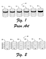
- Fig. 1 illustrates a conventional disk array 12 having six storage disks 13. In this simplified example, there are five storage stripes extending across the storage disks. Fig. 1 highlights data and storage segments of a single one of these five stripes. Data segments of the indicated stripe are indicated by cross-hatching. The corresponding parity segment of this same stripe is illustrated in solid black. Generally, of the six segments comprising any given stripe, five of the segments are data segments and the sixth segment is a parity segment.
- parity storage is referred to as 5 + 1 parity storage, indicating that there are five data segments for every single parity segment.
- This scheme is more generally referred to as N + 1 grouping, where N is the actual number of data segments in a data stripe.
- N + 1 redundancy grouping such as illustrated in Fig. 1 protects against the loss of any single physical storage device. If the storage device fails, its data can be reconstructed from the surviving data. The calculations performed to recover the data are straightforward, and are well-known.
- N + 2 redundancy grouping enhances data protection, it also involves more complex calculations ⁇ both in initially calculating parity segments and in reconstructing any lost data segments.
- N + 2 parity The mathematics of N + 2 parity are well-known and are not the primary subject of this description. However, it is apparent from the brief description given above that N + 2 parity computations are significantly more complex than N + 1 parity computations. In actual implementations of N + 2 disk arrays, this complexity threatens to limit the data throughput of storage device controllers and, consequently, of the overall disk array.
- a task description block queue stores a pointer to each of multiple task description blocks, and each task description block stores information for one parity operation.
- the data for a parity operation is stored in memory, as is a plurality of different coefficients that are used for different parity operations.
- Each task description block stores information used by parity operation logic to perform a single parity operation, including: a type of operation to be performed, a size of the task description block, an optional tag number (for consistency checking), an indication of a response queue into which status results of the operation to be performed are to be stored, pointers to the data stored in memory, a pointer to a subset of the plurality of coefficients, an indication of the number of coefficients in the subset, and a pointer to a result location in memory where results of the parity operation are to be stored by the parity operation logic.
- a pointer to the task description block is stored in the task description block queue, allowing the parity operation logic to perform the parity operation whenever it desires.
- Fig. 1 is a block diagram showing N+1 redundancy grouping in accordance with the prior art.
- Fig. 2 is a block diagram showing N+2 redundancy grouping as used in the described embodiment of the invention.
- Fig. 3 is a block diagram illustrating layout of a memory table in accordance with the invention.
- Fig. 4 illustrates a method of performing parity operations in accordance with certain embodiments of the invention.
- Fig. 5 is a block diagram showing pertinent components of a disk controller in accordance with the invention.
- a redundant data storage system 20 in accordance with the invention utilizes storage disks 22 with data stripes 24.
- Each data stripe 24 comprises a plurality of data segments x 0 through x N-1 and at least two corresponding parity segments P and Q.
- P and Q are derived from the data segments x 0 through x N-1 , from a first set of parity coefficients p 0 through p N-1 , and from a second set of parity coefficients q 0 through q N-1 .
- parity operations are generally classified as parity segment generation operations, parity segment regeneration operations, and data segment reconstruction operations.
- a parity segment generation operation is performed when creating a new data stripe ⁇ the parity segments are created based on completely new data.
- a parity segment regeneration operation is performed with respect to an existing stripe, either when new data causes the addition of a new data segment or when a read/modify/write cycle modifies one or more data segments.
- the parity segments are modified incrementally, without reading an entire data stripe. For example, suppose that new data causes the addition of a new data segment x 4 .
- P NEW P OLD - p 2 x 2OLD + p 2 x 2NEW
- Calculating new P and Q values from the old data segment values involves significantly fewer memory reads than calculating P and Q from scratch after every stripe modification.
- parity segment regeneration operations are further classified as either parity regenerations resulting from added data segments or parity regenerations resulting from a modified data segment.
- f( p a )P +...+ f( p N-1 , p a ) x N-1
- x a f( q 0 , q a )x 0 + f( q 1 , q a ) x 1 + ... + f( q a )Q + ... + f( q N-1 , q a ) x N-1
- f( ) is a transformation function that generates an appropriate coefficient particular to the parity generation code being used.
- Two data segments can be reconstructed from the P and the Q parity segments in combination with the surviving data segments.
- x a ( p, q b + p b q a ) -1 (( q b p 0 + p b q 0 ) x 0 + ( q 0 p 1 + p 0 q 1 ) x 1 + ... + q b P+ ... + ( q b p k + p b q k ) x k + ( q b p k-1 + p b q k+1 ) x k+1 + ... + p b Q + ...
- the second classification group 33 of the array contains the coefficient subsets for parity operations that add incrementally to a stripe.
- Each scenario calls for a different subset of coefficients. For example, if the new or added data segments are x 3 and x 4 , the required coefficient subset to calculate P is ⁇ p 3 , p 4 ).
- the required coefficient subset to calculate P is ⁇ p 2 , p 3 , p 4 , p 5 ⁇ .
- the total of possible ranges within data segments 0 through N-1 depends on the value of N.
- Each coefficient subset of classification group 2 contains two initial parameters that indicate whether the subset applies to calculations of P or to calculations of Q. Each of these initial parameters is set to either "0" or "1". A value of "1" for the first of these coefficients indicates that the calculation involves parity segment P. A value of "1" for the second of these coefficients indicates that the calculation involves parity segment Q. Only one of these two parameters should be set equal to "1" at any given time.
- the remaining coefficients in a Classification 2 subset are the sub-range of coefficients that are used to regenerate P and Q from newly added data stripes.
- the classification group contains a plurality of coefficient subsets of the form:
- Classification group 33 includes a plurality of subsets such as these, depending on N, corresponding to every range of a through b, within the larger range of 0 through N-1.
- the coefficient subsets in this section of the array have varying lengths or sizes, equal to b - a for each operation scenario.
- the coefficient subsets in the third classification group 34 are used to update P and Q when a single data segment is modified. This type of operation updates P and Q segments, given a modified data segment x a .
- the first two parameters of each Classification 3 subset indicate whether the coefficients of the group are applicable to P calculations or to Q calculations.
- Each of these coefficients is set to either "0" or "1".
- a value of "1" for the first of these coefficients indicates that the subset coefficients apply to parity segment P.
- a value of "1" for the second of these coefficients indicates that the subset coefficients apply to involves parity segment Q.
- Each subset contains a single remaining coefficient, corresponding to the data segment x a that is being modified:
- a step 102 comprises pre-calculating individual parity coefficients and pre-selecting subsets of parity coefficients for use in the different parity operations and the different scenarios of parity operations. This step is performed in accordance with the description already given.
- a step 104 comprises storing all of the pre-selected parity coefficient subsets in an indexed linear memory array, where they can be accessed by parity computation logic.
- This step includes pre-formatting the coefficient subsets so that they can be efficiently utilized by hardware-based parity operation logic.
- the individual coefficients of each subset are packed in adjacent bytes or storage units and ordered in a way that is particular to the hardware-based parity operation logic.
- the memory array contains a single coefficient subset corresponding to each different computation scenario.
- Step 106 is straightforward except with regard to the second classification group.
- the second classification group contains coefficient subsets of varying lengths or sizes, making it difficult to determine the offset of a particular coefficient subset.
- the inventors have discovered that when the second classification group is arranged as described, having ordered subgroups of same-sized coefficient subsets, an offset to a particular subgroup can be calculated as a function of the size of the coefficient subsets of the sub-group and of N (the largest number of coefficients contained by any sub-group).
- Step 108 is performed of reading the determined parity coefficient subset from memory.
- Step 110 comprises performing the particular parity operation with the subset of parity coefficients read from memory.
- Fig. 5 illustrates the most pertinent components of a disk controller 200 in accordance with the invention.
- the disk controller includes a microprocessor 201 and associated memory 202.
- the disk controller has a hard disk interface component 203 and a communications component 204.
- the hard disk interface component provides a means of access to the hard disks associated with and controlled by the disk controller.
- the communications component acts as an interface between a host computer and the hard disk controller.
- hard disk controller 200 includes hardware-based parity operation logic 205 in the form of an application-specific integrated circuit (ASIC).
- ASIC application-specific integrated circuit
- the hardware logic When a script is placed in memory, the hardware logic is notified by the presence of the pointer to the TDB for the script in queue 216.
- the hardware logic responds by (a) retrieving the designated coefficients, data segments, and parity segments, (b) performing the appropriate parity operation based on the designated coefficients, (c) returning the data and/or calculated parity segments to memory, and (d) indicating to microprocessor 201 whether the operation has been successfully completed by writing an entry into response queue 218.
- the hardware logic is configured to perform the various different parity operations by summing products of coefficients and data/parity segments.
- the different operations actually vary only in the number and choice of coefficients, data segments, and parity segments. These variables are specified by the script. Thus, the operations lend themselves very conveniently to hardware-based calculations.
- Fig. 6 illustrates an exemplary structure of a task description block 250 in additional detail.
- TDB 250 is described herein with reference to being accessed by hardware logic 205 to perform a parity operation based on the information in TDB 250.
- the memory structure illustrated in Fig. 6 could be used in other systems which perform the parity operation in different manners (e.g., by a microprocessor or other instruction-based processor executing software or firmware).
- a TDB queue 216 includes multiple entries, and each queue entry includes both a request header and a TDB pointer.
- a TDB pointer 252 points to TDB 250 (e.g., stores the starting address for TDB 250 in memory 202), while a corresponding request header 251 stores various information about the requested operation to be carried out based on TDB 250.
- TDB 250 has multiple fields including a header 253, multiple disk data pointers 254, an output pointer 256 and a coefficient pointer and data 258.
- Header 253 includes various information about TDB, and in one implementation includes the following: the size (e.g., in 8-byte double word groups) of TDB 250, an indication of the operation hardware logic 205 is to perform based on the data in TDB 250 (e.g., an identification of one of the five classifications for parity operations discussed above), an execution priority for the operation hardware logic 205 is to perform based on the data in TDB 250 (e.g., different types of operations can be assigned different execution priorities, if desired), and a tag number (if tag-based consistency checking is being performed).
- Each of the disk data pointers 254 points to a location in memory 202 of disk data for the parity operation (each points to one of data blocks 214 of Fig. 5).
- the data pointed to by each pointer 254 can be a data segment or a parity segment of the stripe for which the parity operation is to be performed.
- the pointers 254 are arranged in accordance with an order known by hardware logic 205 (such as from a lowest numbered data segment in the stripe to a highest numbered data segment, followed by the P parity segment and then the Q parity segment), so that hardware logic 205 knows which segment data resides at which memory location for the parity operation.
- Output pointer 256 is a pointer to a location 260 in memory 202 where the results of the parity operation are to be written by parity operation logic 205. Depending on the type of parity operation being performed, the results of the operation can be either the P and Q parity values (e.g., for parity generation or parity regeneration operations), or a data segment(s) value (e.g., for data segment reconstruction). Although a single output pointer 256 is illustrated in Fig. 6, alternatively multiple output pointers may be included in TDB 250 (e.g., for multiple values generated, such as one pointer for the P value and one pointer for the Q value).
- Coefficient pointer and data 258 includes a pointer to a location in coefficient table 30 where the subset of coefficients to be used by parity operation logic 205 are located. Within pointer and data 258 may also be an indication of the number of coefficients that are to be retrieved from the coefficient table (this may be separate from the indication of the type of parity operation that is to be performed as identified in header 253, or alternatively embedded (or inherent) in that indication). Thus, coefficient pointer and data 258 (in combination with header 253) gives parity operation logic 205 the necessary information of where to obtain coefficients for the parity operation and how many coefficients are to be obtained, as well as what parity operation to perform.
- microprocessor 201 adds an entry to TDB queue 216 including a pointer to that TDB and corresponding request header information.
- parity operation logic 205 is certain to have the information it needs to perform the parity operation. Therefore, parity operation logic 205 is not delayed waiting for additional information regarding a parity operation while other parity operations are waiting in the queue, allowing for fast operation of logic 205.
- parity operation logic 205 may optionally perform a consistency check to verify it is using the correct TDB. In one implementation, this consistency check is based on verifying the type of operation and size of the TDB.
- header 253 of TDB 250 includes, as indicated above, an indication of the type of operation to be performed and the size of TDB 250.
- hardware logic 205 accesses the type of operation and TDB size in request header 251 and checks whether they match the type of operation and TDB size stored in header 253.
- hardware logic 205 determines the two operation types and the two TDB sizes match, then the TDB 250 is verified as being the correct TDB; otherwise, the TDB is not the correct TDB and hardware logic 205 indicates to microprocessor 201 that the parity operation has failed due to a command mismatch (e.g., via an entry in response queue 218).
- tag-based consistency checking can be performed, and is referred to herein as tag-based consistency checking.
- microprocessor 201 assigns a tag number to the operation, which is stored in both request header 251 and header 253.
- Hardware logic 205 in addition to verifying the operation type and TDB size, also verifies that the tag numbers in headers 251 and 253 match. If the tag numbers match then the TDB 250 is verified as being the correct TDB (assuming the operation types and TDB sizes also matched); otherwise, the TDB is not the correct TDB and hardware logic 205 indicates to microprocessor 201 that the parity operation has failed due to a tag mismatch (e.g., via an entry in response queue 218).
- the calculated result(s) of the operation is stored in the memory location 260 pointed to by output pointer 256. Additionally, an entry is added to response queue 218 that indicates the status of the operation performed by hardware logic 205. Multiple response queues 218 may exist, and the appropriate one that hardware logic 205 is to add an entry to is indicated in the request header 251 corresponding to the operation.
- Each response queue 218 can include multiple entries, each of which includes a response header and TDB pointer.
- a TDB pointer 262 points to TDB 250 (e.g., stores the starting address for TDB 250 in memory 202), while a corresponding response header 261 stores various information about the operation that was carried out based on TDB 250.
- both TDB pointer 262 and response header 261 are 32-bit values, and response header 261 includes the following information: the size (e.g., in 8-byte double word groups) of TDB 250, an indication of the operation hardware logic 205 was to perform based on the data in TDB 250, whether tag-based consistency checking was to be performed, a "Parity All Zero” flag that is set if a dual parity block calculation results in P and Q parity blocks that contain only zeroes or a single parity block calculation results in a P parity block that contains only zeroes (the flag is also set if the operation is not a parity operation), a "Pattern Match” flag that is set if the source data matches a defined format pattern, an indication of what type of error (if any) occurred in performing the operation, and a tag number (if tag-based consistency checking is being performed).
- the size e.g., in 8-byte double word groups
- tag-based consistency checking was to be performed
- a "Parity All Zero” flag that
- the following errors can be indicated via response header 261: a tag mismatch (the tag in header 251 of queue 216 does not match the tag in header 253 of TDB 250), a command mismatch (the operation type and TDB size in header 251 does not match the operation type and TDB size in header 253), a parity error (a parity error was detected on data returned from memory 202), a memory test data miscompare (if a memory test operation is being performed rather than a parity operation, this indicates that the data returned from memory 202 during a memory test was incorrect), and an illegal command (the operation types indicated in header 251 and header 253 are not legal values).
- a single TDB is used to identify all of the necessary information for parity operation logic 205 to perform a parity operation.
- a single pointer can be used to identify each TDB, allowing multiple parity operations to be easily queued up in TDB queue 216 of Fig. 5.
- Parity operation logic 205 can then process the parity operations in a particular manner (e.g., in a first in/first out (FIFO) manner) by taking operations off queue 216.
- FIFO first in/first out
- a step 274 comprises storing pointers to the disk data memory locations for the parity operation into the TDB, and a step 276 comprises storing a pointer to a result memory location for the parity operation into the TDB.
- a step 278 comprises determining the appropriate coefficient subset to use (analogous to step 106 of Fig. 4 discussed above), and a step 280 comprises storing a pointer to that coefficient subset into the TDB.
- a step 282 comprises storing an indicator of the parity operation classification to the TDB, to inform the parity operation logic which parity operation is to be performed.
- a step 284 comprises adding, to the TDB queue, an entry including a request header and a pointer to this newly populated TDB.
- the indication of the TDB is not added to the TDB queue until all of the data for the parity operation is available in memory 202, allowing the parity operation logic to access memory 202 and perform the parity operation whenever it desires.
- the invention may alternatively be used in other situations.
- the invention may be used to perform a hardware accelerated memory test, in which the memory address to be written to for verification is identified by a field 254 of Fig. 6, hardware logic 205 of Fig. 5 writes test data to the identified memory address, reads the data back from that memory address and stores the data read back in the location identified by pointer 256.
- the invention may be used to perform a copy function, in which the data to be copied is identified by a pointer(s) 254 and the location of the resultant copy identified by pointer 256, and hardware logic 205 performing the copying.
Landscapes
- Engineering & Computer Science (AREA)
- Theoretical Computer Science (AREA)
- Physics & Mathematics (AREA)
- General Engineering & Computer Science (AREA)
- General Physics & Mathematics (AREA)
- Human Computer Interaction (AREA)
- Quality & Reliability (AREA)
- Techniques For Improving Reliability Of Storages (AREA)
- Detection And Correction Of Errors (AREA)
Abstract
Description
- P:
- {p 0, p 1, ... p N-1} and
- Q:
- {q 0, q 1, ... q N-1}
- P:
- {1, 0, p a,...p b} and
- Q:
- {0, 1, q a,...q b}
- P:
- {1, 0, pa} and
- Q:
- {0, 1, q a}
- P:
- { f(p 0, pa), f(p 1, pa), ..., f(pa), ..., f(p N-1, pa) }
- Q:
- { f(q 0, qa), f(q 1, qa), ..., f(qa), ..., f(q N-1, qa)}
- P:
- (p, qb + pb qa)-1 ((qb p0 + pb q0), (q0 p1 + p0 q1),..., qbP,..., (qb
pk + pb qk), (qbpk-1 + pb qk+1),..., pbQ + ... + (qbpN-1 + pbqN-1)) - P:
- (pa qb + pb qa)-1 ((qap0 + pa q0), (qap1 + pa q1), ...,qaP + ... + (qa
pk + pa qk), (qapk-1 + paqk+1),...,paQ,..., (qapN-1 + paqN-1))
- xa:
- { f(p 0,q 0,pa,pb,qa,qb), f(p 1, q 1, pa, pb, qa, qb), ..., f(pa,pb,qa, qb), ..., f(p k, q k, pa, pb, qa, qb), f(p k+1, q k+1, pa, pb, qa, qb), ..., f(pa, p0, qa, qb), ..., f(p N-1, q N-1, pa, pb, qa, qb)}
- xb:
- { f(p 0, q 0, pa, pb, qa, qb), f(p 1, q 1, pa, pb, qa, qb),..., f(pa, pb, qa, qb), ..., f(p k, q k, pa, pb, qa, qb), f(p k+1, q k+1, pa, pb, qa, qb), ..., f(pa, p0, qa, qb), ..., f(p N-1, q N-1, pa, pb, qa, qb)}
- xa:
- (pa, qb + pb, qa)-1(qb, p0 + pb, q0), (pa, qb + pb, qa)-1(qb, p1 + pb,
q1), ..., (pa, qb + pb, qa)-1 qb, ..., (pa, qb + pb, qa)-1(q0, pk + p0,
qk), (pa, qb + pb, qa)-1(q0, pk+1 + p0, qk+1), ..., (pa, qb + pb, qa)-1 pb,
..., (pa, qb + pb, qa)-1 (q0, pN-1 + p0, qN-1) - xb:
- (pa, qb + pb, qa)-1(qb, p0 + pb, q0), (pa, qb + pb, qa)-1(qap1 + pa, q1),
..., (pa, qb + pb, qa)-1 qa, ..., (pa, qb + pb, qa)-1(qa, pk + pa, qk),
(pa, qb + pb, qa)-1(qa, pk+1 + pa, qk+1), ..., (pa, qb + pb, qa)-1 pa, ...
, (pa, qb + pb, qa)-1 (qa, pN-1 + pa, qN-1)
Claims (10)
- A disk controller (200) that performs parity operations in a redundant data storage system, the disk controller (200) comprising:memory (202) to store a plurality of task description blocks (250), each block (250) identifying information for a parity operation to be performed; anda parity operation logic (205), coupled to the memory (202), to access each of the plurality of task description blocks (250) and perform a parity operation based on information identified in the task description block (250).
- A disk controller (200) as recited in claim 1, wherein the memory (202) is further to store a task description block queue (216) having a plurality of entries, wherein each entry identifies one of the plurality of task description blocks (250), and wherein the parity operation logic (205) is to obtain information necessary to perform a parity operation by accessing the task description block (250) identified by one of the plurality of entries.
- A disk controller (200) as recited in claim 1, wherein each of the plurality of task description blocks (250) stores information needed to perform a corresponding parity operation, the information including:a plurality of disk data pointers (254), each identifying a location in the memory (202) for disk data for the parity operation;an output pointer (256) identifying a location in the memory (202) where results of the parity operation are to be stored;a coefficient pointer (258) identifying a location in the memory (202) where parity coefficients for the parity operation are stored; andan identifier (253) of a type of parity operation to be performed.
- A method comprising:storing information (272, 274, 276, 280, 282) for a parity operation in memory (202), wherein the parity operation is to either generate at least one parity segment for a stripe in a redundant data storage system or re-generate at least one data segment for the stripe; andmaking the information available (284) to parity operation logic (205) only after all of the information necessary for the parity operation is stored in the memory (202).
- A method as recited in claim 4, wherein the storing comprises storing the information for the parity operation in the memory (202), and storing pointers to the information into a task description block (250) corresponding to the parity operation.
- A method as recited in claim 4, wherein the storing comprises storing memory location identifiers of the information into a task description block (250) corresponding to the parity operation, and wherein the making comprises adding an identifier of the task description block (250) into a task description block queue (216) that is accessible to the parity operation logic (205).
- A method as recited in claim 4, wherein the storing comprises generating (270) a task description block (250) in the memory (202), the task description block including:a plurality of disk data pointers (254), each identifying a location in the memory (202) for disk data for the parity operation;an output pointer (256) identifying a location in the memory (202) where results of the parity operation are to be stored;a coefficient pointer (258) identifying a location in the memory (202) where parity coefficients for the parity operation are stored; andan identifier (253) of a type of parity operation to be performed.
- A method of making information available to a hardware operation logic (205) to perform operations based on one or more data segments, the method comprising:storing each of the one or more data segments for an operation in a different location in a memory (202);storing, in a task description block (250) corresponding to the operation, a pointer (254) to each of the different locations in memory (202);storing, in the task description block (250), a pointer (256) to a result location in memory (202) where a result of the operation is to be stored; andstoring, in a task description block queue (216), a pointer (252) to the task description block (250).
- A method as recited in claim 8, wherein the hardware operation logic (205) is to perform parity operations, and wherein the method further comprises:storing, in the memory (202), a plurality of coefficients to be used for different parity operations; andstoring, in the task description block (250), a pointer (258) to a subset of the plurality of coefficients that will be used by the parity operation logic (205) for the parity operation.
- A method as recited in claim 8, wherein the storing the pointer (258) to the task description block (250) comprises storing the pointer to the task description block (250) in the task description block queue (216) only after the pointers (254) to each of the plurality of different locations in memory (202) have been stored to the task description block (250), and after the pointer (256) to the result location has been stored to the task description block (250).
Applications Claiming Priority (2)
| Application Number | Priority Date | Filing Date | Title |
|---|---|---|---|
| US808713 | 2001-03-14 | ||
| US09/808,713 US6766480B2 (en) | 2001-03-14 | 2001-03-14 | Using task description blocks to maintain information regarding operations |
Publications (2)
| Publication Number | Publication Date |
|---|---|
| EP1241560A2 true EP1241560A2 (en) | 2002-09-18 |
| EP1241560A3 EP1241560A3 (en) | 2004-09-22 |
Family
ID=25199506
Family Applications (1)
| Application Number | Title | Priority Date | Filing Date |
|---|---|---|---|
| EP02251618A Withdrawn EP1241560A3 (en) | 2001-03-14 | 2002-03-07 | Using task description blocks to maintain information regarding operations |
Country Status (3)
| Country | Link |
|---|---|
| US (1) | US6766480B2 (en) |
| EP (1) | EP1241560A3 (en) |
| JP (1) | JP2002278707A (en) |
Families Citing this family (18)
| Publication number | Priority date | Publication date | Assignee | Title |
|---|---|---|---|---|
| US7529904B2 (en) | 2004-03-31 | 2009-05-05 | International Business Machines Corporation | Storing location identifier in array and array pointer in data structure for write process management |
| US20050273651A1 (en) * | 2004-05-18 | 2005-12-08 | Aristos Logic Corporation | Method of implementing XOR based raid algorithms |
| US20060123312A1 (en) * | 2004-11-19 | 2006-06-08 | International Business Machines Corporation | Method and system for increasing parallelism of disk accesses when restoring data in a disk array system |
| US7392458B2 (en) * | 2004-11-19 | 2008-06-24 | International Business Machines Corporation | Method and system for enhanced error identification with disk array parity checking |
| US20060123271A1 (en) * | 2004-11-19 | 2006-06-08 | International Business Machines Corporation | RAID environment incorporating hardware-based finite field multiplier for on-the-fly XOR |
| US7290199B2 (en) * | 2004-11-19 | 2007-10-30 | International Business Machines Corporation | Method and system for improved buffer utilization for disk array parity updates |
| US7392428B2 (en) * | 2004-11-19 | 2008-06-24 | International Business Machines Corporation | Method and system for recovering from abnormal interruption of a parity update operation in a disk array system |
| JP2006171957A (en) * | 2004-12-14 | 2006-06-29 | Fujitsu Ltd | Storage control apparatus and method |
| US8631284B2 (en) * | 2010-04-30 | 2014-01-14 | Western Digital Technologies, Inc. | Method for providing asynchronous event notification in systems |
| US8762682B1 (en) | 2010-07-02 | 2014-06-24 | Western Digital Technologies, Inc. | Data storage apparatus providing host full duplex operations using half duplex storage devices |
| US8707090B2 (en) | 2011-10-19 | 2014-04-22 | Hitachi, Ltd. | Storage system |
| JP6341795B2 (en) * | 2014-08-05 | 2018-06-13 | ルネサスエレクトロニクス株式会社 | Microcomputer and microcomputer system |
| US10725963B2 (en) | 2015-09-12 | 2020-07-28 | Microsoft Technology Licensing, Llc | Distributed lock-free RDMA-based memory allocation and de-allocation |
| US10713210B2 (en) * | 2015-10-13 | 2020-07-14 | Microsoft Technology Licensing, Llc | Distributed self-directed lock-free RDMA-based B-tree key-value manager |
| US10375167B2 (en) | 2015-11-20 | 2019-08-06 | Microsoft Technology Licensing, Llc | Low latency RDMA-based distributed storage |
| US11436080B2 (en) * | 2017-11-21 | 2022-09-06 | Sony Semiconductor Solutions Corporation | Memory controller, memory, memory system, information processing system, and method of control thereof |
| JP7529947B2 (en) * | 2020-02-20 | 2024-08-07 | エスケイ ハイニックス ナンド プロダクト ソリューションズ コーポレーション | On-SSD erasure correction coding with unidirectional commands |
| CN111679990B (en) * | 2020-06-17 | 2023-08-08 | 北京字节跳动网络技术有限公司 | Test data generation method and device, readable medium and electronic equipment |
Family Cites Families (12)
| Publication number | Priority date | Publication date | Assignee | Title |
|---|---|---|---|---|
| US4433388A (en) * | 1980-10-06 | 1984-02-21 | Ncr Corporation | Longitudinal parity |
| US5134619A (en) * | 1990-04-06 | 1992-07-28 | Sf2 Corporation | Failure-tolerant mass storage system |
| JPH04184634A (en) * | 1990-11-20 | 1992-07-01 | Matsushita Electric Ind Co Ltd | microcomputer |
| JP3409859B2 (en) * | 1991-01-31 | 2003-05-26 | 株式会社日立製作所 | Control method of control device |
| US5446855A (en) * | 1994-02-07 | 1995-08-29 | Buslogic, Inc. | System and method for disk array data transfer |
| JP3209634B2 (en) * | 1994-03-28 | 2001-09-17 | 株式会社日立製作所 | Computer system |
| JP3011035B2 (en) * | 1994-12-08 | 2000-02-21 | 株式会社日立製作所 | Computer system |
| US5893162A (en) * | 1997-02-05 | 1999-04-06 | Transwitch Corp. | Method and apparatus for allocation and management of shared memory with data in memory stored as multiple linked lists |
| US6523087B2 (en) * | 2001-03-06 | 2003-02-18 | Chaparral Network Storage, Inc. | Utilizing parity caching and parity logging while closing the RAID5 write hole |
| US7062702B2 (en) * | 2001-03-14 | 2006-06-13 | Hewlett-Packard Development Company, L.P. | Efficient parity operations |
| US6567891B2 (en) * | 2001-03-14 | 2003-05-20 | Hewlett-Packard Development Company, L.P. | Methods and arrangements for improved stripe-based processing |
| US6687872B2 (en) * | 2001-03-14 | 2004-02-03 | Hewlett-Packard Development Company, L.P. | Methods and systems of using result buffers in parity operations |
-
2001
- 2001-03-14 US US09/808,713 patent/US6766480B2/en not_active Expired - Lifetime
-
2002
- 2002-01-18 JP JP2002009660A patent/JP2002278707A/en active Pending
- 2002-03-07 EP EP02251618A patent/EP1241560A3/en not_active Withdrawn
Also Published As
| Publication number | Publication date |
|---|---|
| US20020166078A1 (en) | 2002-11-07 |
| JP2002278707A (en) | 2002-09-27 |
| EP1241560A3 (en) | 2004-09-22 |
| US6766480B2 (en) | 2004-07-20 |
Similar Documents
| Publication | Publication Date | Title |
|---|---|---|
| US6687872B2 (en) | Methods and systems of using result buffers in parity operations | |
| US6766480B2 (en) | Using task description blocks to maintain information regarding operations | |
| US6567891B2 (en) | Methods and arrangements for improved stripe-based processing | |
| US5805788A (en) | Raid-5 parity generation and data reconstruction | |
| US6138125A (en) | Block coding method and system for failure recovery in disk arrays | |
| US7162678B2 (en) | Extended error correction codes | |
| CA1270333A (en) | Parity spreading to enhance storge access | |
| US5166936A (en) | Automatic hard disk bad sector remapping | |
| US7386758B2 (en) | Method and apparatus for reconstructing data in object-based storage arrays | |
| US7076723B2 (en) | Error correction codes | |
| US20020035666A1 (en) | Method and apparatus for increasing raid write performance by maintaining a full track write counter | |
| JPH04230512A (en) | Method and apparatus for updating record for dasd array | |
| US20040153961A1 (en) | Parity storing method and error block recovering method in external storage subsystem | |
| US6223323B1 (en) | Method for storing parity information in a disk array storage system | |
| US20080195808A1 (en) | Data migration systems and methods for independent storage device expansion and adaptation | |
| US7346733B2 (en) | Storage apparatus, system and method using a plurality of object-based storage devices | |
| CN109358980A (en) | A RAID6 encoding method friendly to data update and single-disk error repair | |
| US7234024B1 (en) | Application-assisted recovery from data corruption in parity RAID storage using successive re-reads | |
| US8489976B2 (en) | Storage controlling device and storage controlling method | |
| US7062702B2 (en) | Efficient parity operations | |
| CN118819428B (en) | Disk parameter management method, device, electronic device and storage medium | |
| JP2006178926A (en) | Storage device, system, and method using multiple object-based storage devices | |
| EP1198891A1 (en) | Data integrity management for data storage systems |
Legal Events
| Date | Code | Title | Description |
|---|---|---|---|
| PUAI | Public reference made under article 153(3) epc to a published international application that has entered the european phase |
Free format text: ORIGINAL CODE: 0009012 |
|
| AK | Designated contracting states |
Kind code of ref document: A2 Designated state(s): AT BE CH CY DE DK ES FI FR GB GR IE IT LI LU MC NL PT SE TR |
|
| AX | Request for extension of the european patent |
Free format text: AL;LT;LV;MK;RO;SI |
|
| PUAL | Search report despatched |
Free format text: ORIGINAL CODE: 0009013 |
|
| AK | Designated contracting states |
Kind code of ref document: A3 Designated state(s): AT BE CH CY DE DK ES FI FR GB GR IE IT LI LU MC NL PT SE TR |
|
| AX | Request for extension of the european patent |
Extension state: AL LT LV MK RO SI |
|
| 17P | Request for examination filed |
Effective date: 20050228 |
|
| AKX | Designation fees paid |
Designated state(s): DE FR GB |
|
| 17Q | First examination report despatched |
Effective date: 20060920 |
|
| STAA | Information on the status of an ep patent application or granted ep patent |
Free format text: STATUS: THE APPLICATION IS DEEMED TO BE WITHDRAWN |
|
| 18D | Application deemed to be withdrawn |
Effective date: 20081204 |