EP1241513A1 - Ultrabroad-band variable-wavelength wavelength-multiplexed pulse waveform shaping device - Google Patents
Ultrabroad-band variable-wavelength wavelength-multiplexed pulse waveform shaping device Download PDFInfo
- Publication number
- EP1241513A1 EP1241513A1 EP00971725A EP00971725A EP1241513A1 EP 1241513 A1 EP1241513 A1 EP 1241513A1 EP 00971725 A EP00971725 A EP 00971725A EP 00971725 A EP00971725 A EP 00971725A EP 1241513 A1 EP1241513 A1 EP 1241513A1
- Authority
- EP
- European Patent Office
- Prior art keywords
- ultra
- broadband
- pulse
- wavelength
- light pulse
- Prior art date
- Legal status (The legal status is an assumption and is not a legal conclusion. Google has not performed a legal analysis and makes no representation as to the accuracy of the status listed.)
- Granted
Links
Images




Classifications
-
- H—ELECTRICITY
- H01—ELECTRIC ELEMENTS
- H01S—DEVICES USING THE PROCESS OF LIGHT AMPLIFICATION BY STIMULATED EMISSION OF RADIATION [LASER] TO AMPLIFY OR GENERATE LIGHT; DEVICES USING STIMULATED EMISSION OF ELECTROMAGNETIC RADIATION IN WAVE RANGES OTHER THAN OPTICAL
- H01S3/00—Lasers, i.e. devices using stimulated emission of electromagnetic radiation in the infrared, visible or ultraviolet wave range
- H01S3/005—Optical devices external to the laser cavity, specially adapted for lasers, e.g. for homogenisation of the beam or for manipulating laser pulses, e.g. pulse shaping
- H01S3/0057—Temporal shaping, e.g. pulse compression, frequency chirping
-
- H—ELECTRICITY
- H01—ELECTRIC ELEMENTS
- H01S—DEVICES USING THE PROCESS OF LIGHT AMPLIFICATION BY STIMULATED EMISSION OF RADIATION [LASER] TO AMPLIFY OR GENERATE LIGHT; DEVICES USING STIMULATED EMISSION OF ELECTROMAGNETIC RADIATION IN WAVE RANGES OTHER THAN OPTICAL
- H01S2301/00—Functional characteristics
- H01S2301/08—Generation of pulses with special temporal shape or frequency spectrum
-
- H—ELECTRICITY
- H01—ELECTRIC ELEMENTS
- H01S—DEVICES USING THE PROCESS OF LIGHT AMPLIFICATION BY STIMULATED EMISSION OF RADIATION [LASER] TO AMPLIFY OR GENERATE LIGHT; DEVICES USING STIMULATED EMISSION OF ELECTROMAGNETIC RADIATION IN WAVE RANGES OTHER THAN OPTICAL
- H01S5/00—Semiconductor lasers
- H01S5/005—Optical components external to the laser cavity, specially adapted therefor, e.g. for homogenisation or merging of the beams or for manipulating laser pulses, e.g. pulse shaping
- H01S5/0057—Optical components external to the laser cavity, specially adapted therefor, e.g. for homogenisation or merging of the beams or for manipulating laser pulses, e.g. pulse shaping for temporal shaping, e.g. pulse compression, frequency chirping
Definitions
- the present invention relates to an ultra-broadband, variable and multiple wavelength, pulse waveform shaping apparatus for use in an optical pulse generator for generating light pulses variable and multiple in wavelength over an ultra-broad bandwidth, i.e., a pulse waveform shaping apparatus for shaping light pulses variable and multiple in wavelength over an ultra-broad bandwidth, in which an ultra-broadband light pulse is produced and is then subjected to two-dimensional modulations both In amplitude and phase effected in a beam of the light pulse.
- Light pulse waveform shaping has hitherto been performed by passing a light pulse having a single preselected center wavelength through either a one-dimensional spatial phase modulator or a one-dimensional spatial amplitude modulator or a combination of the two, or passing a light pulse having a single preselected center wavelength through a two-dimensional spatial phase modulator.
- Light pulse waveform shaping of this type is designed to shape the waveform of a light pulse having a single preselected center wavelength by using a dispersing element to spatially expand the light pulse in dependence on its wavelengths and to effect a phase or an amplitude modulation for each of its wavelength components.
- the instance of using a two-dimensional spatial phase modulator made it possible to obtain light pulses varying in waveform with their spatial positions but having the same one wavelength, and thus again permitted only light pulses of the single center wavelength shaped in waveform to be obtained.
- the present invention is aimed to provide an ultra-broadband, variable and multiple wavelength, waveform shaping apparatus that excels with the ability to yield light pulses shaped in waveform, variable and multiple in wavelength over an ultra-broad bandwidth, the pulses being as short as in the order of pico-seconds or less, or even in the order of femto-seconds.
- an ultra-broadband, variable and multiple wavelength, pulse waveform shaping apparatus of the type to provide optical pulses shaped in waveform, characterized in that it comprises: an ultra-broadband light pulse generating means for receiving from a light source a fundamental wave light pulse having a bandwidth and broadening the bandwidth of said fundamental wave light pulse into an ultra-broadband range to produce an ultra-broadband light pulse; a beam expander means for spatially expanding a beam of the said ultra-broadband light pulse in a direction in a cross section thereof to form an expanded beam of ultra-broadband light pulse; and a wavelength dispersive means for dispersing wavelengths of the ultra-broadband light pulse of the said expanded beam while further spatially expanding the said expanded beam in another direction in a cross section thereof, thereby forming an ultra-broadband light pulse with a beam cross section expanded two-dimensionally.
- the apparatus as set forth in claim 2 in the appended claims may be characterized in that it further includes a two-dimensional spatial amplitude modulator for selecting wavelength bands varying in center frequency along one direction in the ultra-broadband light pulse with the beam cross section expanded two-dimensionally; and a two-dimensional spatial phase modulator for modulating a plurality of light components so selected by wavelength into different phases, whereby light pulses shaped in waveform and variable and multiple in wavelength are formed.
- the apparatus as set forth in claim 3 in the appended claims may also be characterized in that it further includes a beam reducing and waveform shaping means for reducing a two-dimensionally amplitude- and phase-modulated ultra-broadband light pulse component and shaping it into a desired waveform.
- the apparatus as set forth in claim 4 in the appended claims may also be characterized in that the said beam reducing and waveform shaping means comprises at least one of a cylindrical lens and a cylindrical mirror.
- the apparatus as set forth in claim 5 in the appended claims may also be characterized in that the said beam reducing and waveform shaping means comprises at least one of a diffraction grating and a prism, on the both.
- the present invention also provides as set forth in claim 6 in the appended claims an ultra-broadband, variable and multiple wavelength, pulse waveform shaping apparatus characterized in that an ultra-broadband light pulse generated on the basis of a fundamental wave light pulse from a light source has its beam cross section spatially expanded, and its wavelengths dispersed, in one direction in the said beam cross section by at least one of a pair of cylindrical lenses and a pair of cylindrical mirrors and in another direction perpendicular to the said one direction by at least one of a diffraction grating and a prism, respectively; the ultra-broadband light pulse having been expanded is collimated by either a cylindrical lens or a cylindrical mirror; the collimated ultra-broadband light pulse is applied to a two-dimensional spatial amplitude modulator for selection of wavelength bands varying in center wavelength along the said one direction; the selected center wave length light is applied to a two-dimensional spatial phase modulator and a plurality of light components so selected by wavelength is modulated into different phases, respectively, to produce light pulses
- the apparatus so defined in the preceding paragraph may further be characterized as set forth in claim 7 in that an ultra-broadband light pulse modulated by both the said two-dimensional spatial amplitude and phase modulators is reduced in beam cross section by at least one of a cylindrical lens and a cylindrical mirror on the both, or at least one of a diffraction grating and a prism on the both, and thereby is shaped into a desired waveform.
- the apparatus as set forth in claim 8 in the appended claims may also be characterized in that the said two-dimensional spatial amplitude modulator and the said two-dimensional spatial phase modulator are each subjected to a feedback control so as to provide desired pulses.
- the apparatus as set forth in claim 9 in the appended claims may also be characterized in that the said light source is a pulse laser generator of providing an ultra-short pulse of pico-seconds or less.
- the apparatus as set forth in claim 10 in the appended claims may also be characterized in that the said light source for generating the fundamental wave light pulse is any one of a solid state laser, a fiber laser, a semiconductor laser, a dye laser and an optical parametric laser, or a combination thereof with an amplifier system.
- the apparatus as set forth in claim 11 in the appended claims may also be characterized in that the said ultra-broadband light pulse producing means includes at least one nonlinear optical medium adapted for the said fundamental wave light pulse to be passed therethrough.
- the apparatus as set forth in claim 12 in the appended claims may also be characterized in that the said ultra-broadband light pulse is a light pulse in an ultra-broadband and having a pulse dulation of pico-seconds or less.
- the apparatus as set forth in claim 13 in the appended claims may also be characterized in that the said nonlinear optical medium is a hollow fiber filled with either a gas or an ionized gas.
- the apparatus as set forth in claim 14 in the appended claims may also be characterized in that the said nonlinear optical medium is made of any one of a waveguide structure, a bulk structure, a thin film structure, a photonic crystalline structure, a photonic fiber and a liquid, or an optical combination of two or more thereof.
- the apparatus as set forth in claim 15 in the appended claims may also be characterized in that the said nonlinear optical medium has a third-order nonlinear optical property.
- the apparatus as set forth in claim 16 in the appended claims may also be characterized in that the said two-dimensional spatial amplitude modulator includes a two-dimensional space filter for selecting different center amplitudes from the ultra-broadband light pulse.
- the apparatus as set forth in claim 17 in the appended claims may also be characterized in that the said two-dimensional spatial amplitude modulator comprises a first ultra-broadband polarizing plate, a two-dimensional spatial phase modulator, and a second ultra-broadband polarizing plate of which the polarization axis is perpendicular to the polarization axis of the said first polarizing plate.
- the present invention by taking a makeup as mentioned above makes it possible to produce a plurality of optical pulse trains variable and multiple in wavelength, each independently of another and simultaneously or synchronously with another.
- Fig. 1 is a makeup view diagrammatically illustrating one form of embodiment of the ultra-broadband, variable and multiple wavelength, pulse waveform shaping apparatus of the present invention.
- this form of embodiment of the ultra-broadband, variable and multiple wavelength, pulse waveform shaping apparatus of the present invention includes a light source 21 for generating an ultra-short light pulse that is short as in the order of pico-seconds or less, a first ultra-broadband light pulse generating unit 22 for broadening the bandwidth of the light pulse to produce an ultra ⁇ broadband light pulse in the form of a beam, a beam expander 24 for spatially expanding the beam of this ultra-broadband light pulse in a direction (which is here assumed to be along a y-axis) in a cross section of the beam to form an expanded beam of ultra-broadband light pulse, and a wavelength-dispersive unit 26 for dispersing wavelengths of the ultra-broadband light pulse of the expanded beam, while further expanding the beam, in another direction in a cross section of the beam, thereby forming an ultra-broadband light pulse with a beam cross section expanded two-dimensionally.
- a light source 21 for generating an ultra-short light pulse that is
- beam cross section is used to refer to a cross section of the beam cut perpendicular to the direction in which the ultra-broadband light pulse propagates.
- a laser system of any one of a solid-state laser, a fiber laser, a semiconductor laser, a dye laser and an optical parametric laser, or such a laser system combined with an amplifier system.
- a pressure chamber 3 filled with a gas, e.g., a rare gas and having a hollow fiber 4 disposed therein aligned with the optical axis of the laser system and the unit, but may be made simply of such a hollow fiber 4 alone that is filled with a rare gas and aligned with the optical axis.
- a gas e.g., a rare gas and having a hollow fiber 4 disposed therein aligned with the optical axis of the laser system and the unit, but may be made simply of such a hollow fiber 4 alone that is filled with a rare gas and aligned with the optical axis.
- the pressure chamber 3 may be held filled with an ionized gas produced, e.g., by applying a voltage across a pair of electrodes disposed at the opposite ends of the chamber 3 so that the hollow chamber 4 disposed therein can also be held filled with the ionized gas.
- the hollow fiber 4 alone may again be used that is aligned with the optical axis and here held filled with an ionized gas.
- the rare gas as the filler may also be replaced with a liquid.
- the first ultra-broadband light pulse generating unit 22 is also shown to include an optical component such as a spherical lens 2 to condense the light pulse, and a collimator 5 that collimates the condensed light pulse, although they may be disposed separately outside of the unit.
- an optical component such as a spherical lens 2 to condense the light pulse
- a collimator 5 that collimates the condensed light pulse, although they may be disposed separately outside of the unit.
- Fig. 2 illustrates further arrangements that may be adopted in embodying the ultra-broadband, variable and multiple wavelength, pulse waveform shaping apparatus of the present invention, including Fig. 2a that is a makeup view of the arrangement in which the first ultra-broadband light pulse generating unit has at its light incoming side a second ultra-broadband light pulse generating unit and Fig. 2b that is a makeup view of the arrangement in which the first ultra-broadband light pulse generating unit has at its light outgoing side a second ultra-broadband light pulse generating unit.
- ultra-broadband light pulse generating units shown in Figs. 2a and 2b and indicated by reference character 42 (and 44), respectively, are each a combination of the ultra-broadband light pulse generating unit 22 shown in Fig. 1 with the second ultra-broadband light pulse generating unit, indicated by reference character 32
- the first ultra-broadband light pulse generating unit 22 in Fig. 1 may be replaced with the second ultra-broadband light pulse generating unit 32 alone.
- the second ultra-broadband light pulse generating unit 32 shown in Fig. 2 includes a condensing element 34 and a collimator 38 and has a separate nonlinear optical medium structure 36 disposed on the optical axis between them. It should be noted in this connection that the hollow fiber 4 filled with a rare gas or ionized gas is an example of the nonlinear optical medium structure
- An ultra-broadband light pulse is obtainable when a fundamental wave pulse from a laser light source having a selected center wavelength is passed through a nonlinear optical medium to bring about a self-phase modulation effect and thereby to result in an expanded spectrum, or to bring about an induced phase modulation effect between such a fundamental wave pulse and a pulse generated by a nonlinear phenomenon that takes place using the fundamental wave pulse and thereby to result in an expanded spectrum.
- a nonlinear optical medium use may be made of many an inorganic or organic material that is large in the third-order nonlinear optical property.
- use may be made of a waveguide structure, a bulk structure, a thin film, a photonic crystalline structure, a photonic fiber structure or a liquid.
- any structure is sufficient if it can confine a light therein, and it may be a fiber or channel waveguide structure.
- the bulk or the thin film which is a structure that cannot confine a light therein but let it spread, but which can be formed from any material even though it is poor in machinability, use may thus be made of any inorganic or organic material that is large in the third-order nonlinear optical property.
- a photonic crystal is a structure in which atoms are arranged regularly with a period in the order of a light wavelength and is capable confining a light therein.
- a liquid if used may be filled in a transparent vessel.
- the medium is a rare gas and the structure is a hollow fiber filled with a rare gas, and it is made of glass to form a waveguide structure.
- the wavelength dispersive unit 26 in the form of embodiment illustrated may include a collimator in the form of a cylindrical lens or mirror, although they may be separately disposed outside of the unit.
- the ultra-broadband, variable and multiple wavelength, pulse waveform shaping apparatus 20 in the illustrated form of embodiment of the present invention further includes a two-dimensional spatial amplitude modulator 11 for selecting along the y-axis, different wavelength ranges with their respective center wavelengths, of the light pulse beam expanded two-dimensionally, a two-dimensional spatial amplitude modulator 12 for phase-modulating a plurality of light components in the selected wavelength ranges individually, and a beam reducing and waveform shaping unit 28 for reducing the phase-modulated light pulse beam in the direction of x-axis in its beam cross section while shaping it into any waveform as desired to form a multiple wavelength light pulse shaped in waveform. While its detailed explanation is to be given later, for the condensing element use may be made of a cylindrical lens or mirror, and for the pulse waveform shaping section use may be a diffraction grating.
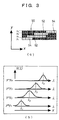
- Fig. 3 conceptionally illustrates the makeup of a two-dimensional spatial amplitude modulator for use in the form of embodiment illustrated and includes Fig. 3a that illustrates in a conceptional view a two-dimensional space filter and Fig. 3b that illustrates in a spectrum view the cutout of wavelengths.
- the two-dimensional spatial amplitude modulator has a two-dimensional space filter 50, e.g., with an array of pixels being 648 (in the direction of x-axis) x 4 (in the direction of y-axis) in number, which is provided with regions 54 transparent, and regions 52 nontransparent to, the light pulse beam.
- the ultra-broadband light pulse through the 2-dimensional space filter 50 allows different center wavelengths as shown in Fig. 3b to be selected and in effect the wavelengths to be cut out.
- Fig. 4 conceptionally illustrates the makeup of another two-dimensional spatial amplitude modulator for use in the form of embodiment illustrated and includes Fig. 4a that illustrates in a conceptional view the makeup of another two-dimensional space filter, Fig. 4b that illustrates an ultra-broadband polarizing plate, Fig. 4c that illustrates a two-dimensional spatial phase modulator and Fig. 4d that illustrates another ultra- broadband polarizing plate.
- the two-dimensional spatial amplitude modulator, 60, shown in Fig. 4 is formed with the first ultra-broadband polarizing plate, 62, the two-dimensional spatial phase modulator, 64, with an array of pixels being 648 (in the direction of x-axis) x 4 (in the direction of y-axis)in number and the second ultra-broadband polarizing plate, 66, having an axis of light polarization orthogonal to that of the first ultra-broadband polarizing plate 62, wherein the members 62, 64 and 66 are laid one on top of another.
- varying the two-dimensional spatial phase modulator 64 in phase varies the amount of light transmitted through the two orthogonal ultra-broadband polarizing plates. This permits a two-dimensional amplitude modulation to be effected.
- numeral 61 in Fig. 4a represents an ultra-broadband light pulse expanded two-dimensionally
- numeral 63 represents an ultra-broadband light pulse modulated in amplitude two-dimensionally.
- indicated by the arrows in Figs. 4b and 4c are the directions of the polarization axises of those plates, the light having whose polarization direction is only transmissive.
- an ultra-broadband light pulse as short as pico-seconds or less is produced and used, which has wavelengths extending over an ultra-broadband between 500 nm and 1000 nm.
- a beam of this ultra-broadband light pulse is spatially expanded in one direction of its cross section, say in the direction of y-axis, by using the beam expander 24, by such as a pair of cylindrical lenses or mirrors therein.
- the beam of ultra-broadband light pulse so spatially expanded is then subjected to wavelength dispersion and second spatial expansion both by the waveform dispersive unit 26 wherein it is spatially expanded in another direction in the same cross section orthogonal to that one section, say in the direction of an x-axis orthogonal to the y-axis.
- the resulting ultra-broadband light pulse then after having been collimated by the collimator such as a cylindrical lens or mirror in the wavelength dispersive unit 26, is subjected in the 2-dimensional spatial amplitude modulator 11 to selection or extraction of different wavelength ranges with their respective center wavelengths (cutout of wavelengths) in the direction of y-axis.
- a resultant plurality of light components with the wavelengths selected is then phase ⁇ modulated by the 2-dimensional spatial phase modulator 12 into different phases.
- a resultant ultra-broadband light pulse phase-modulated is reduced in its beam cross section in the direction of x-axis and thereafter shaped into a waveform as desired, both by the beam reducing and waveform shaping unit 28.
- reducing the ultra-broadband light pulse in its beam cross section in the direction of x-axis corresponds to removing its spread in the direction of x-axis which it had when the wavelengths were dispersed. This makes it possible to derive light pulses with their center wavelengths varying depending on positions in the direction of y-axis and shaped with any waveform as desired and independently of one another, namely multiple wavelength light pulses shaped in wave form.
- monitoring the center wavelength and waveform of each shaped pulse derived to effect feedback control allows the desired center wavelength and waveform to be obtained.
- Fig. 1 is a conceptual makeup view showing one form of embodiment of the ultra-broadband variable and multiple wavelength pulse waveform shaping apparatus according to the present invention.
- the cylindrical lens has a curvature, and the diffraction grating has grooves, both along the y-axis.
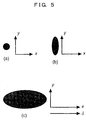
- Fig. 5 diagrammatically illustrates the cross section of an ultra-broadband light pulse beam each after passing through a certain optical element in the present form of embodiment wherein Fig. 5(a) shows a light pulse beam outgoing from the spherical lens 5, Fig. 5(b) shows the cross section of a light pulse beam outgoing from the cylindrical lens 6, 7 for expanding the light pulse beam in its cross section in one direction and Fig. 5(c) shows the cross section of a light pulse beam outgoing from the entrance diffraction grating 9.
- Figs. 6, 7 and 8 show in explanatory views the wavelength cutout function of the two-dimensional spatial amplitude modulator and the independent waveform shaping function by the 2-dimensional spatial phase modulator.
- a light pulse having a center wavelength of 790 nm, a pulse width of 30 fs, a pulse energy of 0.6 mJ and a repetition rate of 1 kHz is generated by a titanium-sapphire laser amplifier system as the light source 1.
- the light pulse is condensed and guided into the ultra-broadband light pulse generating unit 22, which produces an ultra-broadband light pulse of a wavelength range of 500 to 1000 nm.
- the ultra-broadband light pulse generating unit 22 is made of a pressure chamber 3 having, e.g., a sapphire made light inlet and outlet window and filled with argon at a pressure of 3.3 atm and a quartz made hollow fiber 4 having an inner diameter of 0.1 mm and a length of 300 mm.
- the ultra-broadband light pulse generating unit 22 is thus designed so that a light pulse condensed is received at the light entrance end of the quartz made hollow fiber 4.
- the resultant ultra-broadband light pulse is then collimated by the spherical lens 5 having a focal length of 200 mm as the collimator, becoming a beam of light whose cross section is shown in Fig. 5(a).
- the light beam is expanded in its cross section in the direction of y-axis by the beam expander unit 24 comprising the cylindrical lens 6 having a focal length of 20 mm and the cylindrical lens 7 having a focal length of 150 mm.
- the cross section of the expanded beam is shown in Fig. 5(b).
- the light so expanded is then collimated by the collimator comprising a cylindrical lens 10 having a curvature along the x-axis and a focal length of 150 mm.
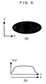
- Fig. 6(a) is a beam cross sectional view of the ultra-broadband light beam on the two-dimensional spatial amplitude modulator while Fig.
- 6(b) is a diagram showing a spectral distribution S( ⁇ ) of the ultra-broadband light beam on the two-dimensional spatial amplitude modulator (indicating that the ⁇ -axis is coincident with the x-axis in the beam cross section).
- the beam cross section has the same wavelength components along the y-axis, it has wavelength components widely distributed along the x-axis corresponding to its spectral distribution S( ⁇ ) since the direction of x-axis is coincident with that of the axis of wavelength ⁇ .
- This two-dimensionally spread light pulse is passed through the two-dimensional spatial amplitude modulator 11 having an array of pixels, for example, 648 (along the x-axis) x 4 (along the y-axis) in number.
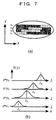
- This array provides as shown in Fig. 7, four (y1, y2, y3 and y4 rows of) one-dimensional spatial amplitude modulators each of which comprises an array of pixels 648 x 1 within the cross section of the light pulse beam. If for these 1-st to 4-th rows of different amplitude modulations are applied, then wavelength components whose center wavelengths vary from one another, ⁇ 1, ⁇ 2, ⁇ 3 and ⁇ 4, can be taken out (the cutout of wavelengths).
- Fig. 7(a) is a diagram illustrating how amplitude modulation by the two-dimensional spatial amplitude modulator is effected
- Fig. 7(b) is a diagram illustrating the spectral distribution S( ⁇ ) after the cutout of wavelengths effected by way of amplitude modulation of the two-dimensional spatial amplitude modulator.
- the light pulse with its center wavelengths cut out that vary depending on positions along the y-axis is passed through the two-dimensional spatial phase modulator comprising an array of pixels 648 (along the x-axis) x 4 (along the y-axis) in number and having a maximum amount of phase modulation less than 2 ⁇ , and thereby subjected to phase modulation for each of the y1 row to the y4 row.
- the beam cross section as shown in Fig. 8(a) comes to have a phase modulation applied thereto for each of the pixels independently of one another.
- Fig. 8(a) is a diagram illustrating how phase modulation by the two-dimensional spatial phase modulator is effected, Fig.
- Fig. 8(b) is a cross sectional view of the beam outgoing from an exit diffraction grating 14, and Fig. 8(c) is a diagram illustrating pulses independently shaped in waveform and having different center wavelengths (namely an ultra-broadband, variable wavelength, multiple wavelength, waveform shaped pulses).
- the light pulse beam is condensed on the diffraction grating 14 into the direction of x-axis. Then, the light pulse beam diffracted by the exit diffraction grating 14, whose beam cross section at this point of time is as shown in Fig. 8(b), provides a pulse shaped in waveform having a center frequency ⁇ 1 at a position y1, a pulse shaped in waveform having a center frequency ⁇ 2 at a position y2, a pulse shaped in waveform having a center frequency ⁇ 3 at a position y3, and a pulse shaped in waveform having a center frequency ⁇ 4.
- the respective pulse shaping patterns can be controlled each independently of one another to provide respective trains of pulses each of a waveform as desired.
- Fig. 8(c) shows temporal waveforms of such independently shaped trains of pulses (which are shown in terms of pulse intensity versus time: I(t)).
- a mirror 15 adjusts the directions in which ultra-broadband variable wavelength, wavelength multiple, waveform shaped pulses thus generated are to propagate.
- An ultra-broadband, variable and multiple wavelength, pulse waveform shaping apparatus with the use of a two-dimensional spatial amplitude modulator and a two-dimensional phase modulator, is capable of producing ultra-broadband light pulses, and generating a plurality of trains of optical pulses with wavelengths variable in an ultra-broadband, independently of one another but concurrently or even synchronously, and thus in a manner hitherto hard to effect.
- the present invention is also applicable to optical information and transmission processing and optical computing by temporal, multiple wavelength and temporal parallel control and is thus extremely great in its industrial value.
Landscapes
- Physics & Mathematics (AREA)
- Electromagnetism (AREA)
- Engineering & Computer Science (AREA)
- Plasma & Fusion (AREA)
- Optics & Photonics (AREA)
- Optical Modulation, Optical Deflection, Nonlinear Optics, Optical Demodulation, Optical Logic Elements (AREA)
- Lasers (AREA)
Abstract
Description
Claims (17)
- An ultra-broadband, variable and multiple wavelength, pulse waveform shaping apparatus of the type to provide optical pulses shaped in waveform, characterized in that it comprises:an ultra-broadband light pulse generating means for receiving from a light source a fundamental wave light pulse having a bandwidth and broadening the bandwidth of said fundamental wave light pulse into an ultra-broadband range to produce an ultra-broadband light pulse;a beam expander means for spatially expanding a beam of said ultra-broadband light pulse in a direction in a cross section of said beam to form an expanded beam of ultra-broadband light pulse; anda wavelength dispersive means for dispersing wavelengths of the ultra-broadband light pulse of said expanded beam while further spatially expanding said expanded beam in another direction in a cross section thereof, thereby forming an ultra-broadband light pulse with a beam cross section thereof expanded two-dimensionally.
- An ultra-broadband, variable and multiple wavelength, pulse waveform shaping apparatus as set forth in claim 1, characterized in that it further includes:a two-dimensional spatial amplitude modulator for selecting wavelength bands varying in center frequency along one direction in the ultra-broadband light pulse with the beam cross section expanded two-dimensionally; anda two-dimensional spatial phase modulator for modulating a plurality of light components so selected by wavelength into different phases, whereby light pulses shaped in waveform and variable and multiple in wavelength are formed.
- An ultra-broadband, variable and multiple wavelength, pulse waveform shaping apparatus as set forth in claim 1 or claim 2, characterized in that it further includes a beam reducing and waveform shaping means for reducing a two-dimensionally amplitude- and phase-modulated ultra-broadband light pulse component in said another direction in a cross section thereof and shaping it into a desired waveform.
- An ultra-broadband, variable and multiple wavelength, pulse waveform shaping apparatus as set forth in claim 3, characterized in that said beam reducing and waveform shaping means comprises at least one of a cylindrical lens and a cylindrical mirror, on the both.
- An ultra-broadband, variable and multiple wavelength, pulse waveform shaping apparatus as set forth in claim 3, characterized in that said beam reducing and waveform shaping means comprises at least one of a diffraction grating and a prism, on the both.
- An ultra-broadband, variable and multiple wavelength, pulse waveform shaping apparatus characterized in that an ultra-broadband light pulse generated on the basis of a fundamental wave light pulse from a light source has its beam cross section spatially expanded in one direction, and its wavelengths dispersed in another direction, in said beam cross section by at least one of a pair of cylindrical lenses and a pair of cylindrical mirrors on the both and by at least one of a diffraction grating and a prism on the both, respectively; the ultra-broadband light pulse having been expanded is collimated by either a cylindrical lens or a cylindrical mirror on the both; the collimated ultra-broadband light pulse is applied to a two-dimensional spatial amplitude modulator for selection of wavelength bands varying in center wavelength along said one direction; and a plurality of light components so selected by wavelength is modulated into different phases, respectively, to produce light pulses shaped in waveform and variable and multiple in wavelength.
- An ultra-broadband, variable and multiple wavelength, pulse waveform shaping apparatus as set forth in claim 6, characterized in that an ultra-broadband light pulse modulated by both said two-dimensional spatial amplitude and phase modulators is reduced in beam cross section by at least one of a cylindrical lens and a cylindrical mirror on the both, or at least one of a diffraction grating and a prism on the both, and thereby is shaped into a desired waveform.
- An ultra-broadband, variable and multiple wavelength, pulse waveform shaping apparatus as set forth in any one of claims 2, 3, 6 and 7, characterized in that said two-dimensional spatial amplitude modulator and said two-dimensional spatial phase modulator are each subjected to a feedback control so as to provide desired pulses.
- An ultra-broadband, variable and multiple wavelength, pulse waveform shaping apparatus as set forth in claim I or claim 6, characterized in that said light source is a pulse laser generator of providing an ultra-short pulse of pico-seconds or less.
- An ultra-broadband, variable and multiple wavelength, pulse waveform shaping apparatus as set forth in any one of claims 1, 6 and 9, characterized in that said light source for generating said fundamental wave light pulse is any one of a solid state laser, a fiber laser, a semiconductor laser, a dye laser and an optical parametric laser, or a combination thereof with an amplifier system.
- An ultra-broadband, variable and multiple wavelength, pulse waveform shaping apparatus as set forth in claim 1 or claim 6, characterized in that said ultra-broadband light pulse producing means includes at least one nonlinear optical medium adapted for said fundamental wave light pulse to be passed therethrough.
- An ultra-broadband, variable and multiple wavelength, pulse waveform shaping apparatus as set forth in any one of claims 1, 6 and 11, characterized in that said ultra-broadband light pulse is a light pulse in an ultra-broadband and of pico-seconds or less.
- An ultra-broadband, variable and multiple wavelength, pulse waveform shaping apparatus as set forth in claim 11, characterized in that said nonlinear optical medium is a hollow fiber filled with either a gas or an ionized gas.
- An ultra-broadband, variable and multiple wavelength, pulse waveform shaping apparatus as set forth in claim 11 or claim 13, characterized in that said nonlinear optical medium is made of any one of a waveguide structure, a bulk structure, a thin film structure, a photonic crystalline structure, a photonic fiber and a liquid, or an optical combination of two or more thereof.
- An ultra-broadband, variable and multiple wavelength, pulse waveform shaping apparatus as set forth in any one of claims 11, 13 and 14, characterized in that said nonlinear optical medium has a third-order nonlinear optical property.
- An ultra-broadband, variable and multiple wavelength, pulse waveform shaping apparatus as set forth in any one of claims 2, 6 and 8, characterized in that said two-dimensional spatial amplitude modulator includes a two-dimensional space filter for selecting different center wavelength from the ultra-broadband light pulse.
- An ultra-broadband, variable and multiple wavelength, pulse waveform shaping apparatus as set forth in any one of claims 2, 6 and 8, characterized in that said two-dimensional spatial amplitude modulator comprises a first ultra-broadband polarizing plate, a two-dimensional spatial phase modulator, and a second ultra-broadband polarizing plate whose polarizing axis is perpendicular to the polarizing axis of said first polarizing plate.
Applications Claiming Priority (3)
| Application Number | Priority Date | Filing Date | Title |
|---|---|---|---|
| JP35487199 | 1999-12-14 | ||
| JP35487199A JP4474625B2 (en) | 1999-12-14 | 1999-12-14 | Ultra-wideband variable wavelength multiplex pulse waveform shaping device |
| PCT/JP2000/007699 WO2001044863A1 (en) | 1999-12-14 | 2000-11-01 | Ultrabroad-band variable-wavelength wavelength-multiplexed pulse waveform shaping device |
Publications (3)
| Publication Number | Publication Date |
|---|---|
| EP1241513A1 true EP1241513A1 (en) | 2002-09-18 |
| EP1241513A4 EP1241513A4 (en) | 2004-08-11 |
| EP1241513B1 EP1241513B1 (en) | 2010-09-22 |
Family
ID=18440473
Family Applications (1)
| Application Number | Title | Priority Date | Filing Date |
|---|---|---|---|
| EP00971725A Expired - Lifetime EP1241513B1 (en) | 1999-12-14 | 2000-11-01 | Ultrabroad-band variable-wavelength wavelength-multiplexed pulse waveform shaping device |
Country Status (5)
| Country | Link |
|---|---|
| US (1) | US6826209B1 (en) |
| EP (1) | EP1241513B1 (en) |
| JP (1) | JP4474625B2 (en) |
| DE (1) | DE60045011D1 (en) |
| WO (1) | WO2001044863A1 (en) |
Cited By (2)
| Publication number | Priority date | Publication date | Assignee | Title |
|---|---|---|---|---|
| US6826209B1 (en) * | 1999-12-14 | 2004-11-30 | Japan Science And Technology Corporation | Ultrabroad-band variable-wavelength wavelength-multiplexed pulse waveform shaping device |
| EP1511133A1 (en) * | 2003-08-27 | 2005-03-02 | Fujitsu Limited | Multi-wavelength light source apparatus |
Families Citing this family (30)
| Publication number | Priority date | Publication date | Assignee | Title |
|---|---|---|---|---|
| US7002149B2 (en) | 2001-11-26 | 2006-02-21 | Japan Science And Technology Agency | Delay time modulation femtosecond time-resolved scanning probe microscope apparatus |
| US8184984B1 (en) * | 2002-11-13 | 2012-05-22 | Finisar Corporation | Optical transceiver having a modulating component |
| JP4565082B2 (en) * | 2004-03-26 | 2010-10-20 | 学校法人慶應義塾 | Transparent material processing method and transparent material processing apparatus |
| US7447401B2 (en) * | 2005-02-28 | 2008-11-04 | Optium Australia Pty Limited | Optical communications system |
| JP2007088384A (en) * | 2005-09-26 | 2007-04-05 | Univ Of Miyazaki | Vacuum ultraviolet laser light source, vacuum ultraviolet laser generation method |
| JP2007101842A (en) | 2005-10-04 | 2007-04-19 | Fujitsu Ltd | Optical element having photonic crystal structure |
| US7486401B2 (en) * | 2006-02-27 | 2009-02-03 | Honeywell International Inc. | Laser medium pumping system for a gyroscope |
| US7756420B2 (en) | 2006-03-24 | 2010-07-13 | Lightkey Optical Components, Llc | System and method for shaping a waveform |
| JP2007334225A (en) * | 2006-06-19 | 2007-12-27 | Mitsubishi Electric Corp | Optical pulse width conversion device and optical pulse width conversion method |
| US7742511B2 (en) * | 2006-09-29 | 2010-06-22 | Pyrophotonics Lasers Inc. | Method and system for a pulsed laser source emitting shaped optical waveforms |
| US7428253B2 (en) * | 2006-09-29 | 2008-09-23 | Pyrophotonics Lasers Inc. | Method and system for a pulsed laser source emitting shaped optical waveforms |
| US8023179B2 (en) * | 2007-03-15 | 2011-09-20 | Ofs Fitel Llc | Enhanced continuum generation in nonlinear bulk optic materials |
| JP5125245B2 (en) * | 2007-06-15 | 2013-01-23 | 独立行政法人情報通信研究機構 | Optical waveform shaping device |
| US20100074630A1 (en) * | 2008-09-25 | 2010-03-25 | Tim Olson | System and method for shaping a waveform |
| US9414887B2 (en) * | 2009-03-13 | 2016-08-16 | Robert R. Alfano | Method and apparatus for producing supercontinuum light for medical and biological applications |
| US8964801B2 (en) * | 2009-06-11 | 2015-02-24 | Esi-Pyrophotonics Lasers, Inc. | Method and system for stable and tunable high power pulsed laser system |
| EP2470325A4 (en) * | 2009-09-24 | 2017-07-05 | Electro Scientific Industries, Inc. | Method and apparatus to scribe a line in a thin film material using a burst of laser pulses with beneficial pulse shape |
| US8890025B2 (en) | 2009-09-24 | 2014-11-18 | Esi-Pyrophotonics Lasers Inc. | Method and apparatus to scribe thin film layers of cadmium telluride solar cells |
| JP2013512111A (en) * | 2009-11-30 | 2013-04-11 | イ−エスアイ−パイロフォトニクス レーザーズ インコーポレイテッド | Method and apparatus for scribing a line in a thin film using a series of laser pulses |
| US8254015B2 (en) * | 2009-12-23 | 2012-08-28 | Institut National D'optique | System and method for the spatial tailoring of laser light using temporal phase modulation |
| JP2012238695A (en) * | 2011-05-11 | 2012-12-06 | Canon Inc | Terahertz wave generating device and measurement device having the same |
| JP5838532B2 (en) * | 2011-06-15 | 2016-01-06 | 国立研究開発法人情報通信研究機構 | Wavelength selective polarization controller |
| DE102012023605B4 (en) * | 2012-12-04 | 2022-03-03 | Toptica Photonics Ag | Method and device for the synthesis of electromagnetic radiation |
| US9748737B2 (en) * | 2013-03-07 | 2017-08-29 | Hamamatsu Photonics K.K. | Laser element and laser device |
| WO2015130651A1 (en) * | 2014-02-28 | 2015-09-03 | Imra America, Inc. | Multi-wavelength, ultrashort pulse generation and delivery, with applications in microscopy |
| WO2016129155A1 (en) * | 2015-02-13 | 2016-08-18 | ソニー株式会社 | Semiconductor laser device assembly |
| JP6780985B2 (en) * | 2016-08-31 | 2020-11-04 | 浜松ホトニクス株式会社 | Terahertz wave generator and terahertz wave generation method |
| IL299683B2 (en) * | 2017-01-09 | 2025-08-01 | Max Planck Gesellschaft | Broadband light source device and method for generating a broadband light pulse |
| CN113631999B (en) | 2019-03-25 | 2023-05-16 | Asml荷兰有限公司 | Frequency widening device and method |
| CN114289859A (en) * | 2022-02-28 | 2022-04-08 | 北京理工大学 | Hemispherical resonance gyroscope base electrode shaping method of space-time frequency shaping femtosecond laser |
Family Cites Families (7)
| Publication number | Priority date | Publication date | Assignee | Title |
|---|---|---|---|---|
| JPH0212227A (en) | 1988-06-30 | 1990-01-17 | Hamamatsu Photonics Kk | Light pulse generating device |
| JP2711773B2 (en) * | 1992-02-03 | 1998-02-10 | 国際電信電話株式会社 | Optical waveform shaping device |
| US5263039A (en) * | 1992-05-18 | 1993-11-16 | The University Of Rochester | System for generating shaped optical pulses and measuring optical pulses using spectral beam deflection (SBD) |
| US5682262A (en) | 1995-12-13 | 1997-10-28 | Massachusetts Institute Of Technology | Method and device for generating spatially and temporally shaped optical waveforms |
| US6404786B1 (en) * | 1997-08-25 | 2002-06-11 | Sony Corporation | Laser beam generating apparatus |
| US6483858B1 (en) * | 1999-11-23 | 2002-11-19 | Southeastern University Research Assn. | Injection mode-locking Ti-sapphire laser system |
| JP4474625B2 (en) * | 1999-12-14 | 2010-06-09 | 独立行政法人科学技術振興機構 | Ultra-wideband variable wavelength multiplex pulse waveform shaping device |
-
1999
- 1999-12-14 JP JP35487199A patent/JP4474625B2/en not_active Expired - Fee Related
-
2000
- 2000-11-01 WO PCT/JP2000/007699 patent/WO2001044863A1/en not_active Ceased
- 2000-11-01 US US10/149,987 patent/US6826209B1/en not_active Expired - Fee Related
- 2000-11-01 EP EP00971725A patent/EP1241513B1/en not_active Expired - Lifetime
- 2000-11-01 DE DE60045011T patent/DE60045011D1/en not_active Expired - Lifetime
Cited By (3)
| Publication number | Priority date | Publication date | Assignee | Title |
|---|---|---|---|---|
| US6826209B1 (en) * | 1999-12-14 | 2004-11-30 | Japan Science And Technology Corporation | Ultrabroad-band variable-wavelength wavelength-multiplexed pulse waveform shaping device |
| EP1511133A1 (en) * | 2003-08-27 | 2005-03-02 | Fujitsu Limited | Multi-wavelength light source apparatus |
| US7315557B2 (en) | 2003-08-27 | 2008-01-01 | Fujitsu Limited | Multi-wavelength light source apparatus |
Also Published As
| Publication number | Publication date |
|---|---|
| US6826209B1 (en) | 2004-11-30 |
| JP4474625B2 (en) | 2010-06-09 |
| WO2001044863A1 (en) | 2001-06-21 |
| DE60045011D1 (en) | 2010-11-04 |
| EP1241513B1 (en) | 2010-09-22 |
| JP2001174764A (en) | 2001-06-29 |
| EP1241513A4 (en) | 2004-08-11 |
Similar Documents
| Publication | Publication Date | Title |
|---|---|---|
| US6826209B1 (en) | Ultrabroad-band variable-wavelength wavelength-multiplexed pulse waveform shaping device | |
| US7576907B1 (en) | Phase and amplitude light pulse shaping using a one-dimensional phase mask | |
| Weiner | Femtosecond pulse shaping using spatial light modulators | |
| US20080291946A1 (en) | Fast quantum gates with ultrafast chirped pulses | |
| EP3830913B1 (en) | Pulse configurable fiber laser unit | |
| EP0815484A1 (en) | Apparatus and methods for routing of optical beams via time-domain spatial-spectral filtering | |
| EP3438625A1 (en) | Pulsed light waveform measurement method and waveform measurement device | |
| US10191343B2 (en) | Device and process for forming laser pulses | |
| Liu et al. | Using an acousto-optic modulator as a fast spatial light modulator | |
| JP2001174764A5 (en) | ||
| US20060017999A1 (en) | Diffraction-based pulse shaping with a 2D optical modulator | |
| US6930821B2 (en) | Nonlinear frequency mixer using quasi-phase-matching gratings having beam-modifying patterns | |
| Wang et al. | 20-fs pulse shaping with a 512-element phase-only liquid crystal modulator | |
| EP4194840A1 (en) | Dispersion measurement device and dispersion measurement method | |
| WO2010060460A1 (en) | Device for multispectral and spatial shaping | |
| EP2821848A1 (en) | Laser device | |
| Kalyoncu et al. | Fast arbitrary waveform generation by using digital micromirror arrays | |
| GB2410122A (en) | Tunable source of electromagnetic radiation | |
| JP3837564B2 (en) | Broadband optical sideband generation method and broadband optical sideband generation apparatus | |
| Stone et al. | Spatiotemporal femtosecond pulse shaping using a MEMS-based micromirror SLM | |
| Schriever et al. | Shaped UV Pulses with 20 fs Substructures | |
| Hosaka et al. | Programmable Quantum Linear Interference with Pulse Shaping of Quantum Light | |
| Wefers et al. | Programmable generation of ultrafast optical waveforms: recent advances in theory and technology | |
| Kumar De et al. | Modulation of cross-correlation traces by pulse-shaping with spatial mask | |
| Morita et al. | of the complex electric field Ent)(w) after spectral phase modulation is ex |
Legal Events
| Date | Code | Title | Description |
|---|---|---|---|
| PUAI | Public reference made under article 153(3) epc to a published international application that has entered the european phase |
Free format text: ORIGINAL CODE: 0009012 |
|
| 17P | Request for examination filed |
Effective date: 20020709 |
|
| AK | Designated contracting states |
Kind code of ref document: A1 Designated state(s): AT BE CH CY DE DK ES FI FR GB GR IE IT LI LU MC NL PT SE TR |
|
| RAP1 | Party data changed (applicant data changed or rights of an application transferred) |
Owner name: CITIZEN WATCH CO. LTD. Owner name: JAPAN SCIENCE AND TECHNOLOGY AGENCY |
|
| RBV | Designated contracting states (corrected) |
Designated state(s): DE FR GB NL |
|
| A4 | Supplementary search report drawn up and despatched |
Effective date: 20040629 |
|
| 17Q | First examination report despatched |
Effective date: 20040830 |
|
| 17Q | First examination report despatched |
Effective date: 20040830 |
|
| RAP1 | Party data changed (applicant data changed or rights of an application transferred) |
Owner name: JAPAN SCIENCE AND TECHNOLOGY AGENCY Owner name: CITIZEN HOLDINGS CO., LTD. |
|
| GRAP | Despatch of communication of intention to grant a patent |
Free format text: ORIGINAL CODE: EPIDOSNIGR1 |
|
| GRAS | Grant fee paid |
Free format text: ORIGINAL CODE: EPIDOSNIGR3 |
|
| GRAA | (expected) grant |
Free format text: ORIGINAL CODE: 0009210 |
|
| AK | Designated contracting states |
Kind code of ref document: B1 Designated state(s): DE FR GB NL |
|
| REG | Reference to a national code |
Ref country code: GB Ref legal event code: FG4D |
|
| REF | Corresponds to: |
Ref document number: 60045011 Country of ref document: DE Date of ref document: 20101104 Kind code of ref document: P |
|
| REG | Reference to a national code |
Ref country code: NL Ref legal event code: VDEP Effective date: 20100922 |
|
| PG25 | Lapsed in a contracting state [announced via postgrant information from national office to epo] |
Ref country code: NL Free format text: LAPSE BECAUSE OF FAILURE TO SUBMIT A TRANSLATION OF THE DESCRIPTION OR TO PAY THE FEE WITHIN THE PRESCRIBED TIME-LIMIT Effective date: 20100922 |
|
| PLBE | No opposition filed within time limit |
Free format text: ORIGINAL CODE: 0009261 |
|
| STAA | Information on the status of an ep patent application or granted ep patent |
Free format text: STATUS: NO OPPOSITION FILED WITHIN TIME LIMIT |
|
| 26N | No opposition filed |
Effective date: 20110623 |
|
| REG | Reference to a national code |
Ref country code: DE Ref legal event code: R097 Ref document number: 60045011 Country of ref document: DE Effective date: 20110623 |
|
| PGFP | Annual fee paid to national office [announced via postgrant information from national office to epo] |
Ref country code: FR Payment date: 20131120 Year of fee payment: 14 Ref country code: GB Payment date: 20131120 Year of fee payment: 14 |
|
| PGFP | Annual fee paid to national office [announced via postgrant information from national office to epo] |
Ref country code: DE Payment date: 20140124 Year of fee payment: 14 |
|
| REG | Reference to a national code |
Ref country code: DE Ref legal event code: R119 Ref document number: 60045011 Country of ref document: DE |
|
| GBPC | Gb: european patent ceased through non-payment of renewal fee |
Effective date: 20141101 |
|
| REG | Reference to a national code |
Ref country code: FR Ref legal event code: ST Effective date: 20150731 |
|
| PG25 | Lapsed in a contracting state [announced via postgrant information from national office to epo] |
Ref country code: GB Free format text: LAPSE BECAUSE OF NON-PAYMENT OF DUE FEES Effective date: 20141101 Ref country code: DE Free format text: LAPSE BECAUSE OF NON-PAYMENT OF DUE FEES Effective date: 20150602 |
|
| PG25 | Lapsed in a contracting state [announced via postgrant information from national office to epo] |
Ref country code: FR Free format text: LAPSE BECAUSE OF NON-PAYMENT OF DUE FEES Effective date: 20141201 |