EP1241503A2 - Optical module and method for producing the same - Google Patents
Optical module and method for producing the same Download PDFInfo
- Publication number
- EP1241503A2 EP1241503A2 EP02005319A EP02005319A EP1241503A2 EP 1241503 A2 EP1241503 A2 EP 1241503A2 EP 02005319 A EP02005319 A EP 02005319A EP 02005319 A EP02005319 A EP 02005319A EP 1241503 A2 EP1241503 A2 EP 1241503A2
- Authority
- EP
- European Patent Office
- Prior art keywords
- frame
- optical
- optical module
- module according
- elastic body
- Prior art date
- Legal status (The legal status is an assumption and is not a legal conclusion. Google has not performed a legal analysis and makes no representation as to the accuracy of the status listed.)
- Withdrawn
Links
- 230000003287 optical effect Effects 0.000 title claims abstract description 236
- 238000004519 manufacturing process Methods 0.000 title claims description 5
- 230000003014 reinforcing effect Effects 0.000 claims abstract description 30
- 239000013307 optical fiber Substances 0.000 claims description 81
- 239000010408 film Substances 0.000 claims description 17
- 239000011521 glass Substances 0.000 claims description 11
- 229910052751 metal Inorganic materials 0.000 claims description 7
- 239000002184 metal Substances 0.000 claims description 7
- 239000010409 thin film Substances 0.000 claims description 6
- 230000010287 polarization Effects 0.000 abstract description 21
- 230000000717 retained effect Effects 0.000 abstract description 7
- 239000000463 material Substances 0.000 description 16
- 238000007789 sealing Methods 0.000 description 16
- 230000008859 change Effects 0.000 description 7
- 230000000694 effects Effects 0.000 description 7
- 239000011347 resin Substances 0.000 description 6
- 229920005989 resin Polymers 0.000 description 6
- 125000006850 spacer group Chemical group 0.000 description 6
- XLYOFNOQVPJJNP-UHFFFAOYSA-N water Substances O XLYOFNOQVPJJNP-UHFFFAOYSA-N 0.000 description 6
- 229910052782 aluminium Inorganic materials 0.000 description 4
- XAGFODPZIPBFFR-UHFFFAOYSA-N aluminium Chemical compound [Al] XAGFODPZIPBFFR-UHFFFAOYSA-N 0.000 description 4
- 230000006872 improvement Effects 0.000 description 4
- 239000000853 adhesive Substances 0.000 description 3
- 238000004891 communication Methods 0.000 description 3
- 150000001875 compounds Chemical class 0.000 description 3
- 230000004907 flux Effects 0.000 description 3
- 229920002635 polyurethane Polymers 0.000 description 3
- 239000004814 polyurethane Substances 0.000 description 3
- 229930182556 Polyacetal Natural products 0.000 description 2
- XUIMIQQOPSSXEZ-UHFFFAOYSA-N Silicon Chemical compound [Si] XUIMIQQOPSSXEZ-UHFFFAOYSA-N 0.000 description 2
- 239000004809 Teflon Substances 0.000 description 2
- 229920006362 Teflon® Polymers 0.000 description 2
- 230000002411 adverse Effects 0.000 description 2
- 239000000470 constituent Substances 0.000 description 2
- 229920001971 elastomer Polymers 0.000 description 2
- 230000007246 mechanism Effects 0.000 description 2
- -1 polyethylene Polymers 0.000 description 2
- 229920006324 polyoxymethylene Polymers 0.000 description 2
- 229910052710 silicon Inorganic materials 0.000 description 2
- 239000010703 silicon Substances 0.000 description 2
- RZVAJINKPMORJF-UHFFFAOYSA-N Acetaminophen Chemical compound CC(=O)NC1=CC=C(O)C=C1 RZVAJINKPMORJF-UHFFFAOYSA-N 0.000 description 1
- 229920000106 Liquid crystal polymer Polymers 0.000 description 1
- 239000004977 Liquid-crystal polymers (LCPs) Substances 0.000 description 1
- FYYHWMGAXLPEAU-UHFFFAOYSA-N Magnesium Chemical compound [Mg] FYYHWMGAXLPEAU-UHFFFAOYSA-N 0.000 description 1
- 239000004698 Polyethylene Substances 0.000 description 1
- 239000004721 Polyphenylene oxide Substances 0.000 description 1
- 230000005540 biological transmission Effects 0.000 description 1
- 230000000903 blocking effect Effects 0.000 description 1
- 239000000919 ceramic Substances 0.000 description 1
- 230000005494 condensation Effects 0.000 description 1
- 238000009833 condensation Methods 0.000 description 1
- 238000001816 cooling Methods 0.000 description 1
- 238000000151 deposition Methods 0.000 description 1
- 239000000835 fiber Substances 0.000 description 1
- PCHJSUWPFVWCPO-UHFFFAOYSA-N gold Chemical compound [Au] PCHJSUWPFVWCPO-UHFFFAOYSA-N 0.000 description 1
- 229910052737 gold Inorganic materials 0.000 description 1
- 239000010931 gold Substances 0.000 description 1
- 238000009434 installation Methods 0.000 description 1
- 239000011810 insulating material Substances 0.000 description 1
- 229910000833 kovar Inorganic materials 0.000 description 1
- 229910052749 magnesium Inorganic materials 0.000 description 1
- 239000011777 magnesium Substances 0.000 description 1
- 239000007769 metal material Substances 0.000 description 1
- 238000000034 method Methods 0.000 description 1
- 239000000203 mixture Substances 0.000 description 1
- 238000000465 moulding Methods 0.000 description 1
- 239000003921 oil Substances 0.000 description 1
- 239000004033 plastic Substances 0.000 description 1
- 229920003023 plastic Polymers 0.000 description 1
- 229920000515 polycarbonate Polymers 0.000 description 1
- 239000004417 polycarbonate Substances 0.000 description 1
- 229920000573 polyethylene Polymers 0.000 description 1
- 229920006380 polyphenylene oxide Polymers 0.000 description 1
- 239000005297 pyrex Substances 0.000 description 1
- 230000002787 reinforcement Effects 0.000 description 1
- 230000004044 response Effects 0.000 description 1
- 238000000926 separation method Methods 0.000 description 1
- 230000035939 shock Effects 0.000 description 1
- 230000002889 sympathetic effect Effects 0.000 description 1
- 239000002699 waste material Substances 0.000 description 1
Images




Classifications
-
- G—PHYSICS
- G02—OPTICS
- G02B—OPTICAL ELEMENTS, SYSTEMS OR APPARATUS
- G02B6/00—Light guides; Structural details of arrangements comprising light guides and other optical elements, e.g. couplings
- G02B6/24—Coupling light guides
- G02B6/42—Coupling light guides with opto-electronic elements
- G02B6/4201—Packages, e.g. shape, construction, internal or external details
- G02B6/4249—Packages, e.g. shape, construction, internal or external details comprising arrays of active devices and fibres
-
- G—PHYSICS
- G02—OPTICS
- G02B—OPTICAL ELEMENTS, SYSTEMS OR APPARATUS
- G02B6/00—Light guides; Structural details of arrangements comprising light guides and other optical elements, e.g. couplings
- G02B6/24—Coupling light guides
- G02B6/42—Coupling light guides with opto-electronic elements
- G02B6/4201—Packages, e.g. shape, construction, internal or external details
- G02B6/4204—Packages, e.g. shape, construction, internal or external details the coupling comprising intermediate optical elements, e.g. lenses, holograms
-
- G—PHYSICS
- G02—OPTICS
- G02B—OPTICAL ELEMENTS, SYSTEMS OR APPARATUS
- G02B6/00—Light guides; Structural details of arrangements comprising light guides and other optical elements, e.g. couplings
- G02B6/24—Coupling light guides
- G02B6/42—Coupling light guides with opto-electronic elements
- G02B6/4201—Packages, e.g. shape, construction, internal or external details
- G02B6/4219—Mechanical fixtures for holding or positioning the elements relative to each other in the couplings; Alignment methods for the elements, e.g. measuring or observing methods especially used therefor
-
- G—PHYSICS
- G02—OPTICS
- G02B—OPTICAL ELEMENTS, SYSTEMS OR APPARATUS
- G02B6/00—Light guides; Structural details of arrangements comprising light guides and other optical elements, e.g. couplings
- G02B6/24—Coupling light guides
- G02B6/42—Coupling light guides with opto-electronic elements
- G02B6/4201—Packages, e.g. shape, construction, internal or external details
- G02B6/4219—Mechanical fixtures for holding or positioning the elements relative to each other in the couplings; Alignment methods for the elements, e.g. measuring or observing methods especially used therefor
- G02B6/4236—Fixing or mounting methods of the aligned elements
- G02B6/4244—Mounting of the optical elements
-
- G—PHYSICS
- G02—OPTICS
- G02B—OPTICAL ELEMENTS, SYSTEMS OR APPARATUS
- G02B6/00—Light guides; Structural details of arrangements comprising light guides and other optical elements, e.g. couplings
- G02B6/24—Coupling light guides
- G02B6/42—Coupling light guides with opto-electronic elements
- G02B6/4201—Packages, e.g. shape, construction, internal or external details
- G02B6/4251—Sealed packages
- G02B6/4253—Sealed packages by embedding housing components in an adhesive or a polymer material
-
- G—PHYSICS
- G02—OPTICS
- G02B—OPTICAL ELEMENTS, SYSTEMS OR APPARATUS
- G02B6/00—Light guides; Structural details of arrangements comprising light guides and other optical elements, e.g. couplings
- G02B6/24—Coupling light guides
- G02B6/26—Optical coupling means
- G02B6/27—Optical coupling means with polarisation selective and adjusting means
- G02B6/2753—Optical coupling means with polarisation selective and adjusting means characterised by their function or use, i.e. of the complete device
- G02B6/278—Controlling polarisation mode dispersion [PMD], e.g. PMD compensation or emulation
-
- G—PHYSICS
- G02—OPTICS
- G02B—OPTICAL ELEMENTS, SYSTEMS OR APPARATUS
- G02B6/00—Light guides; Structural details of arrangements comprising light guides and other optical elements, e.g. couplings
- G02B6/24—Coupling light guides
- G02B6/26—Optical coupling means
- G02B6/28—Optical coupling means having data bus means, i.e. plural waveguides interconnected and providing an inherently bidirectional system by mixing and splitting signals
- G02B6/293—Optical coupling means having data bus means, i.e. plural waveguides interconnected and providing an inherently bidirectional system by mixing and splitting signals with wavelength selective means
- G02B6/29304—Optical coupling means having data bus means, i.e. plural waveguides interconnected and providing an inherently bidirectional system by mixing and splitting signals with wavelength selective means operating by diffraction, e.g. grating
- G02B6/29305—Optical coupling means having data bus means, i.e. plural waveguides interconnected and providing an inherently bidirectional system by mixing and splitting signals with wavelength selective means operating by diffraction, e.g. grating as bulk element, i.e. free space arrangement external to a light guide
- G02B6/2931—Diffractive element operating in reflection
-
- G—PHYSICS
- G02—OPTICS
- G02B—OPTICAL ELEMENTS, SYSTEMS OR APPARATUS
- G02B6/00—Light guides; Structural details of arrangements comprising light guides and other optical elements, e.g. couplings
- G02B6/24—Coupling light guides
- G02B6/26—Optical coupling means
- G02B6/28—Optical coupling means having data bus means, i.e. plural waveguides interconnected and providing an inherently bidirectional system by mixing and splitting signals
- G02B6/293—Optical coupling means having data bus means, i.e. plural waveguides interconnected and providing an inherently bidirectional system by mixing and splitting signals with wavelength selective means
- G02B6/29379—Optical coupling means having data bus means, i.e. plural waveguides interconnected and providing an inherently bidirectional system by mixing and splitting signals with wavelength selective means characterised by the function or use of the complete device
- G02B6/29398—Temperature insensitivity
-
- G—PHYSICS
- G02—OPTICS
- G02B—OPTICAL ELEMENTS, SYSTEMS OR APPARATUS
- G02B6/00—Light guides; Structural details of arrangements comprising light guides and other optical elements, e.g. couplings
- G02B6/24—Coupling light guides
- G02B6/42—Coupling light guides with opto-electronic elements
- G02B6/4201—Packages, e.g. shape, construction, internal or external details
- G02B6/4204—Packages, e.g. shape, construction, internal or external details the coupling comprising intermediate optical elements, e.g. lenses, holograms
- G02B6/4213—Packages, e.g. shape, construction, internal or external details the coupling comprising intermediate optical elements, e.g. lenses, holograms the intermediate optical elements being polarisation selective optical elements
-
- G—PHYSICS
- G02—OPTICS
- G02B—OPTICAL ELEMENTS, SYSTEMS OR APPARATUS
- G02B6/00—Light guides; Structural details of arrangements comprising light guides and other optical elements, e.g. couplings
- G02B6/24—Coupling light guides
- G02B6/42—Coupling light guides with opto-electronic elements
- G02B6/4201—Packages, e.g. shape, construction, internal or external details
- G02B6/4204—Packages, e.g. shape, construction, internal or external details the coupling comprising intermediate optical elements, e.g. lenses, holograms
- G02B6/4215—Packages, e.g. shape, construction, internal or external details the coupling comprising intermediate optical elements, e.g. lenses, holograms the intermediate optical elements being wavelength selective optical elements, e.g. variable wavelength optical modules or wavelength lockers
-
- G—PHYSICS
- G02—OPTICS
- G02B—OPTICAL ELEMENTS, SYSTEMS OR APPARATUS
- G02B6/00—Light guides; Structural details of arrangements comprising light guides and other optical elements, e.g. couplings
- G02B6/24—Coupling light guides
- G02B6/42—Coupling light guides with opto-electronic elements
- G02B6/4201—Packages, e.g. shape, construction, internal or external details
- G02B6/4256—Details of housings
- G02B6/426—Details of housings mounting, engaging or coupling of the package to a board, a frame or a panel
Definitions
- the present invention relates to an optical module and a method for producing the optical module, and particularly relates to an optical module of a micro-optics type constituted by a lens, a diffraction grating, a filter, and so on, and a method for producing the optical module.
- Amicro-optics type optical module is disclosed, for example, in Japanese Patent Laid-Open No. 73020/1997.
- Micro optical elements such as a lens, a plane mirror, a concave mirror, a filter, a diffraction grating and a prism are individually aligned and fixed to the bottom surface of a box-shaped package having one surface opened.
- the micro optical elements are aligned and fixed to a plane base.
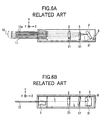
- Figs. 6A and 6B show an example of an optical multiplexing/demultiplexing device which has a diffraction grating provided in Littrow mounting and which is mounted in a box-shaped package having one surface opened.
- Figs. 7A and 7B show another example of the optical multiplexing/demultiplexing device which is mounted on a plane base. These examples are illustrated by the present inventors for comparison purpose with the present invention.
- an input/output optical fiber array 1, a diffraction grating 3, a polarization compensating filter 5 and a collimator lens 2 are provided in a box-shaped package 8 having a top surface opened.
- the polarization compensating filter 5 is provided to compensate for the polarization dependency of the diffraction efficiency of the diffraction grating 3.
- the collimator lens 2 is provided to convert divergent light from an input optical fiber 11 into parallel light and converge diffracted parallel light from the diffraction grating 3 on respective optical fibers 12a of an output optical fiber array 12.
- the diffraction grating 3, the polarization compensating filter 5 and the collimator lens 2 are aligned and fixed to the box-shaped package 8 through a diffraction grating fixing stage 31, a polarization compensating filter stage 51 and a collimator lens fixing platform 21 respectively, which are disposed on the bottom surface of the box-shaped package 8.
- the input/output optical fiber array 1 is provided with the input optical fiber 11 and the output optical fiber array 12.
- the output optical fiber array 12 has a plurality of optical fibers 12a.
- the box-shaped package 8 has such high rigidity that the shape of the package 8 can be retained against external force. Thus, it is possible to form an optical module which has a stable optical axis and which makes a stable operation against mechanical vibration and stress.
- an input/output optical fiber array 1, a diffraction grating 3, a polarization compensating filter 5 and a collimator lens 2 are provided on a plane base 7 in the same manner as in Figs. 6A and 6B.
- the diffraction grating 3, the polarization compensating filter 5 and the collimator lens 2 are aligned and fixed to the plane base 7 through a diffraction grating fixing stage 31, a polarization compensating filter stage 51 and a collimator lens fixing platform 21, respectively.
- the plane base 7 is different from the box-shaped package 8 having one surface opened in Figs. 6A and 6B in that the plane base 7 has open space.
- units for finely adjusting the respective optical components such as a micro-motion stage, can be disposed around the optical module easily.
- the optical components can be aligned and fixed.
- the related-art optical modules have problems as follows.
- the optical components are fixed to the bottom surface of the box-shaped package 8 so that there is a space between each of the optical components and each of the opposite side surfaces of the box-shaped package.
- the package becomes large in size compared with the optical components.
- each of the optical components cannot be finely adjusted through surface sides but the open surface side.
- finely adjusting mechanisms such as micro-motion stages interfere with one another mechanically.
- the optical components are fixed to the plane base 7 so that there is a distance between each of the optical components and each of end surfaces of the plane base 7.
- the package becomes large in size compared with the optical components.
- the plane base 7 there is indeed a space around the optical system so that mechanisms which can finely adjust a plurality of optical components simultaneously can be disposed around the optical module, unlike the case shown in Figs. 6A and 6B.
- the plane base 7, however, has a structure in which an optical path as a whole is retained by the surface of the plane base 7, so that the total rigidity of the optical module is lowered.
- the invention is developed in consideration of such problems in the related art. It is an object of the invention to provide a small-sized optical module in which a large number of small-sized optical components is adjusted and aligned accurately while the optical module makes a stable operation against harsh external force or mechanical vibration and thermal disturbance for use in optical communication.
- the box-shaped package 8 is so high in rigidity that the box-shaped package 8 cannot be deformed or broken easily even in the case where mechanical impact particularly in a drop test is applied on the box-shaped package 8.
- the impact is, however, transmitted directly to the respective optical components mounted and fixed inside the box-shaped package 8 by the adhesive agent, so that the optical components may be dropped out due to the separation of the adhesive agent.
- the box-shaped package 8 is made of low expansion glass such as pyrex glass which is a material having a small linear expansion coefficient, thermal stability is excellent but the box-shaped package itself is broken in a drop test carried out on the related-art optical module, so that the related-art optical module loses its function.
- the invention is developed in consideration of such problems in the related art. It is an object of the invention to provide a micro-optics type optical module which is constituted by a lens, a diffraction grating, a filter, and so on, chiefly for use in optical communication and which has properties stable against mechanical impact and is thin enough to be mounted on an electric printed board. It is another object of the invention to provide an optical module in which only a required portion can be exchanged to a new one for the improvement of the function or at the time of a failure.
- the optical module has a structure in which the inner frame containing optical components such as a lens, a diffraction grating and a filter mounted therein is fixedly retained to the outer frame through the elastic body.
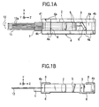
- Figs. 1A and 1B are a plan view and a side sectional view showing the configuration of an optical module according to this embodiment.
- This optical module has a rectangular frame 4 as a frame, an input/output optical fiber array 1 as an optical input/output unit, a collimator lens 2 as a lens, a polarization compensating filter 5 as a filter, a diffraction grating 3, and reinforcing members 6 as a reinforcing unit.
- the rectangular frame 4 has open surfaces provided in two opposite surfaces (top and bottom surfaces as two surfaces crossing the Y-direction perpendicularly in this embodiment).
- the rectangular frame 4 is made of a material having rigidity.
- An input optical fiber 11 and an output optical fiber array 12 are provided in the input/output optical fiber array 1.
- the output optical fiber array 12 is provided with a plurality of optical fibers 12a.
- the collimator lens 2 converts divergent light from the input optical fiber 11 into parallel light and converges diffracted parallel light from the diffraction grating 3 on core end faces of the respective optical fibers 12a of the output optical fiber array 12.
- the polarization compensating filter 5 compensates for the polarization dependency of the diffraction efficiency of the diffraction grating 3.
- One or more reinforcing members 6 are fixedly bonded to the open surfaces of the rectangular frame 4 in order to prevent the rectangular frame 4 from being deformed by external force acting obliquely on the rectangular frame 4.
- the input/output optical fiber array 1 is fixed to a light-transmissible surface 41 provided as one surface of the rectangular frame 4.
- the collimator lens 2 and the polarization compensating filter 5 are inserted into the rectangular frame 4 through the open surfaces of the rectangular frame 4, and opposite side surfaces of the collimator lens 2 and opposite side surfaces of the polarization compensating filter 5 are fixedly bonded to the side surfaces of the rectangular frame 4.
- the diffraction grating 3 is rotated around the Y-axis, the diffraction grating 3 is adjusted angularly as follows. First, the bottom surface of the diffraction grating 3 is fixedly bonded to the reinforcing member 6. Then, the diffraction grating 3 is aligned. Finally, the reinforcement members 6 are fixed to the open surfaces of the rectangular frame 4.
- This optical module performs optical multiplexing/demultiplexing as follows. Emitted light with wavelengths ⁇ 1 , ⁇ 2 , ..., and ⁇ n multiplexed becomes divergent light after it emerges from the light-transmissible surface 41 to which the input optical fiber 11 is fixed. This divergent light is condensed by the collimator lens 2 and divided by the diffraction grating 3 into ray groups ( ⁇ 1 , ⁇ 2 , ..., and ⁇ n ) in accordance with wavelengths having respective desired diffraction angles. The polarization compensating filter 5 compensates for the diffraction efficiency difference between s-polarization and p-polarization of the diffraction grating.
- the collimator lens 2 converges and coupled the luminous flux with the respective wavelengths again onto the core end faces of the optical fibers 12a respectively in the output optical fiber array 12.
- outputs are obtained.
- the lines from the input optical fiber 11 down to the diffraction grating 3 and from the diffraction grating 3 up to the respective optical fibers 12a of the output optical fiber array 12 designate main rays.
- each of the collimator lens 2 and the polarization compensating filter 5 is substantially equal to the distance between the opposite side surfaces of the rectangular frame 4. There is, however, a margin enough to allow these optical components to move between the opposite side surfaces of the rectangular frame 4.
- the optical components are inserted in the rectangular frame 4 through the two opposite open surfaces of the rectangular frame 4. After the optical components are adjusted and aligned, the opposite side surfaces of each of the optical components are fixed to the side surfaces of the rectangular frame 4.
- the optical module in this embodiment uses the rectangular frame 4 having two opposite open surfaces. Accordingly, optical components can be inserted in the rectangular frame 4 through the open surfaces easily, so that a finely adjustable, highly accurate and highly functional optical module can be assembled and mounted.
- the rectangular frame 4 is reinforced with the reinforcing members 6 so as to be prevented from deformation, the optical axis can be stabilized against disturbance such as mechanical vibration.
- low expansion glass (Tempax made by Schott Corporation) is used for the rectangular frame 4 and the reinforcing members 6 so that the structure of the optical system in the Z-direction becomes stable even against temperature changes.
- the external dimensions of the rectangular frame 4 are 20 mm in width (in the X-direction), 7 mm in height (in the Y-direction) and 80 mm in total length (in the Z-direction).
- the rectangular frame 4 is produced by bonding two rectangular parallelepipeds 4a measuring 4 mm thick by 7 mm high by 80 mm long to two rectangular parallelepipeds 4b measuring 4 mm thick by 7 mm high by 12 mm long.
- the rectangular frame 4 is produced by the combination of four rectangular parallelepipeds in such a manner in this embodiment, the respective rectangular parallelepipeds may be fixed by fitting through hooks provided in the rectangular parallelepipeds.
- the mode of division of the frame is not limited to this, but the shape may be trapezoidal.
- the rectangular frame 4 as a whole may be produced by integral molding.
- the optical module according to this embodiment was installed on a stand with a cooling fan, and the input optical fiber 11 and the output optical fiber array 12 were mounted on the stand at a distance of about 10 mm from the optical module. Then, a change of the optical output was measured. In addition, for comparison with this embodiment, a change of the optical output was measured on an optical module in which optical components were fixed on the plane base 7 as shown in Figs. 7A and 7B. In this case, the thickness of the plane base 7 was set to 4 mm, and low expansion glass (Tempax) was used. The whole length of the optical system was set to 80 mm, and the collimator lens 2 and the polarization compensating filter 5 were self-supported and fixedly bonded on one side of the plane base 7. In addition, the reinforcing members 6 shown in Figs. 1A and 1B were bonded to the plane base 7 so that the diffraction grating 3 was retained in the same manner as shown in Figs. 1A and 1B.
- the optical module according to this embodiment is so small that the shortest side of the rectangular frame is 7 mm long. Accordingly, the optical module can be mounted easily even on a stand having a large number of electric printed boards provided at narrow intervals of 12.7 mm (a half inch).
- the embodiment may be modified as other modes to be carried out as follows.
- the invention may be applied also to the case where a frame having opposite side surfaces parallel to each other and having end portions curved is used. That is, any frame can be used if the frame has side surfaces opposite to each other.
- the shapes and mounting positions of the reinforcing members are not limited thereto.
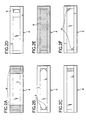
- triangular reinforcing members may be provided in four inner corners of the rectangular frame (Fig. 2B), or a quadrangular reinforcing member may be provided in an inner side of the rectangular frame 4 (Fig. 2C), or a curved reinforcing member may be provided in a corner of the rectangular frame (Fig. 2D), or a reinforcing member may be provided to cover the whole of an open surface of the rectangular frame (Fig. 2E).
- triangular reinforcing members may be provided in two opposite corners (Fig. 2F). That is, the reinforcing members have a structure to prevent the rectangular frame 4 from being deformed by oblique stress and can be provided in any region except the light-transmitting region of the light-transmissible surface through which light comes in and goes out.
- the embodiment has shown the case where low expansion glass is used for the rectangular frame 4 so that the light-transmissible surface 41 is light-transmissible as a whole, the invention may be applied also to the case where only the region on which the input optical fiber 11 and the output optical fiber array 12 are installed is light-transmissible.
- the invention may be applied also to the case where ceramics, metal or plastics is used. That is, any material may be used if the quantity of deformation of the material caused by external force is low enough to keep optical properties of the material.
- the embodiment has shown the case where the input/output optical fiber array 1 constituted by the input optical fiber 11 and the output optical fiber array 12 is used as an optical input/output unit, the invention may be applied also to the case where a light-receiving element array such as a photodiode array is used in place of the output optical fiber array 12.
- a light-receiving element array such as a photodiode array
- light-receiving elements for receiving light with respective wavelengths are arrayed in positions where luminous flux with the respective wavelengths are converged.
- the embodiment has shown the case where the optical module is used as a demultiplexer in which multiplexed light emitted from the input optical fiber 11 is demultiplexed by the diffraction grating into rays to be supplied to the respective optical fibers 12a of the output optical fiber array 12, the invention may be applied also to the case where the optical module is used as a multiplexer instead of a demultiplexer. That is, the output optical fiber array 12 may be replaced by an input optical fiber array. In this case, light with respective wavelengths entering optical fibers 12a of the input optical fiber array 12 may be multiplexed by the diffraction grating 3, and the multiplexed rays may be outputted from an output optical fiber provided in place of the input optical fiber 11.
- a light-emitting element array such as a laser diode array may be provided in place of the output optical fiber array 12.
- light with respective wavelengths emitted from the light-emitting element array may be multiplexed by the diffraction grating 3, and the multiplexed rays may be outputted from an output optical fiber provided in place of the input optical fiber 11.
- the optical module can be used both as a multiplexer and as a demultiplexer, a light-receiving light-emitting element array constituted by a mixture of light-emitting elements and light-receiving elements may be provided in place of the combination of the input optical fiber 11 and the output optical fiber array 12.
- optical components are fixed to opposite side surfaces of a frame.
- the frame used is high in rigidity and small in linear expansion coefficient, it is possible to provide an optical module which can make a stable operation against harsh external force or mechanical vibration and thermal disturbance for use in optical communication.
- a frame provided with two open surfaces when a frame provided with two open surfaces is used, a plurality of small-sized optical components can be aligned and fixed by fine adjustment.
- the rigidity of the optical module can be enhanced by providing reinforcing members on the frame.
- FIG. 3A and 3B An optical module according to a second embodiment of the invention will be described with reference to Figs. 3A and 3B.
- the frame 4 used in the first embodiment is used as an inner frame 4 in the second embodiment, and the second embodiment further uses an outer frame 106.
- Figs. 3A and 3B are a plan view and a side sectional view showing the configuration of an optical module according to this embodiment.
- This optical module has an inner box, i.e. an inner frame, 4, an elastic body 7 provided on side surfaces of the inner box 4, an outer frame 106 provided on side surfaces of the elastic body 7, and an input/output optical fiber array 1 fixed to a light-transmissible surface 41 provided in the inner frame 4.
- the inner frame 4 is fixed to the outer frame 106 through the elastic body 7.
- the elastic body 7 is provided only on the side surfaces of the inner frame 4 but not provided on the top and bottom surfaces of the inner frame 4 (in which two surfaces crossing the Y-axis perpendicularly in Figs.
- 3A and 3B are regarded as the top and bottom surfaces respectively).
- open surfaces are provided in two opposite surfaces (which are two surfaces crossing the Y axis perpendicularly in Figs. 3A and 3B) of the outer frame 106. That is, the outer frame 106 has a structure in which the outer frame 106 does not touch the inner frame 4 but touches only the elastic body 7.
- a collimator lens 2, a polarization compensating filter 5 and a diffraction gratng 3 are provided in the inner frame 4, and these components are fixedly bonded to the inner frame 4.
- the collimator lens 2 converts divergent light from the input optical fiber 11 into parallel light and converges diffraction parallel light from the diffraction grating 3 on respective optical fibers 12a of an output optical fiber array 12.
- the polarization compensating filter 5 compensates for the polarization dependency of the diffraction efficiency of the diffraction grating 3.
- the input optical fiber 11 and the output optical fiber array 12 are provided in the input and output optical fiber array 1.
- the output optical fiber array 12 has a plurality of optical fibers 12a.
- the optical module is fixed to an electric printed board by screws (not shown) inserted into a plurality of holes 70 (four holes in this embodiment) such as threaded holes provided in the outer frame 106.
- a plurality of holes 70 four holes in this embodiment
- the inner box 4 provided with the optical system is floated, through the elastic body 7, with respect to the outer frame 106 fixed to the electric printed board or the like. Hence, it is possible to block the influence of mechanical impact or vibration on the optical system.
- This optical module performs optical multiplexing/demultiplexing as follows. Emitted light with wavelengths ⁇ 1 , ⁇ 2 , ..., and ⁇ n multiplexed becomes divergent light after it emerges from the light-transmissible surface 41 to which the input optical fiber 11 is fixed. This divergent light is condensed by the collimator lens 2 and divided by the diffraction grating 3 into ray groups ( ⁇ 1 , ⁇ 2 , ..., and ⁇ n ) in accordance with wavelengths having desired diffraction angles respectively.
- the polarization compensating filter 5 compensates for the diffraction efficiency difference between s-polarization and p-polarization of the diffraction grating.
- the collimator lens 2 converges and couples the luminous flux with the respective wavelengths again on core end faces of the optical fibers 12a, respectively, in the output optical fiber array 12.
- outputs are obtained.
- the lines from the input optical fiber 11 down to the diffraction grating 3 and from the diffraction grating 3 up to the respective optical fibers 12a of the output optical fiber array 12 designate main rays.
- the inner frame 4 was constituted by a combination of a frame and two plates.
- the frame was formed by bonding and fixing two rectangular parallelepipeds measuring 4 mm thick by 5.5 mm high by 80 mm long and two rectangular parallelepipeds measuring 4 mm thick by 5.5 mm high by 12 mm long.
- the two plates were 1 mm thick and fixedly bonded to the upper and bottom surfaces of the frame.
- the internal dimensions of the inner frame 4 were 12mm in width (in the X-direction in Figs.
- the optical module (length in the Y-direction in Fig. 3B) in which the outer frame 106 was added to the inner frame 4 could be made 8 mm.
- the optical module could be mounted on one of electric printed boards arrayed at narrow intervals of 12.7 mm on a stand.
- Polyacetal (linear expansion coefficient: 8.5 ⁇ 10 -5 /°C) was used for the outer frame 106.
- Polyphenylene oxide (linear expansion coefficient: 2.7 ⁇ 10 -5 /°C) may be used instead.
- a sealing compound made of polyurethane (Pel-Urethane Model MU-102 made by Nippon Pelnox Corporation, with a linear expansion coefficient of 22 ⁇ 10 -5 /°C) was used for the elastic body 7.
- the elastic body 7 of the optical module in this embodiment was produced as follows. First, a spacer jig (not shown) made of Teflon having the same internal dimensions as those of the outer frame 106 and having a predetermined height was disposed on the upper and bottom surfaces of the inner frame 4. Then, the input/output optical fiber array 1 was fixed by the outer frame 106 and a dividing/capping portion 61 as a dividing unit. Then, a dispenser was used so that the sealing compound made of polyurethane was charged in between the outer frame 106 and the inner frame 4 through a hole provided in the spacer jig. Then, the sealing compound was hardened on a hot plate at 60°C for 2 hours. Since the spacer jig was made of Teflon, the spacer jig could be removed easily from the hardened elastic body. Thus, the elastic body 7 shown in Figs. 3A and 3B could be formed.
- the optical module produced thus was subjected to a drop test in which the optical module was dropped from a height of 1m. As a result, it could be confirmed that there was no recognized damage in the inner frame 4 and that there was no change in the optical properties.
- the dividing/capping portion 61 was removed and then the inner frame 4 was pressed from its one side while a cutter knife was inserted between the outer frame 106 and the elastic body 7. As a result, the inner frame 4 and the outer frame 106 could be separated from each other. Further, after the elastic body 7 adhering to the circumference of the inner frame 4 was partially cut with the cutter knife, the elastic body 7 was pulled and drawn. As a result, the elastic body 7 could be removed from the circumference of the inner frame 4.
- an optical multiplexing/demultiplexing module optical system mounted in another inner frame 4 was mounted on this outer frame 106 in the manner described above and subjected to a similar drop test. As a result, it could be confirmed that there was no recognized damage in the inner frame 4 and that there was no change in the optical properties.
- the embodiment has shown the case where polyurethane, low expansion glass and polyacetal are used for the elastic body 7, the inner frame 4 and the outer frame 106 respectively. These materials are, however, not limited to this specific combination.
- the elastic body 7 may be made of a material selected from a silicon resin, a rubber-based adhesive agent, a rubber O-ring, an elastic spacer, and so on. That is, any material may be used if it has elasticity and is capable of absorbing the linear expansion coefficient difference between the inner frame 4 and the outer frame 106 and capable of blocking external vibration, particularly vibration with a frequency close to the specific frequency of the optical components provided in the inner frame.
- the inner frame 4 is preferably made of a material represented by a metal material such as kovar or a liquid crystal polymer, which has a small linear expansion coefficient particularly with respect to the direction of the optical axis and which is low in cost and high in rigidity.
- a metal such as aluminum or magnesium, or a resin such as polyethylene or polycarbonate may be used for the outer frame 106. It is, however, desired that the material of the outer frame 106 is not deformed by mechanical impact and has a linear expansion coefficient close to that of the material of electric printed boards.
- the inner frame 4 and the outer frame 106 have low wettability to the elastic body 7 so that the inner frame 4 and the outer frame 106 can be separated easily from each other. It is, however, possible to use a high-wettability material if the material is coated with silicon oil to thereby reduce the wettability.
- the whole of the light-transmissible surface 41 transmits light.
- Another configuration may be made if the region of installation of the input optical fiber 11 and the output optical fiber array 12 can transmit light.
- Figs. 4A and 4B are a plan view and a side sectional view showing the configuration of an optical module according to this embodiment. Since the optical module according to this embodiment has constituent portions the same as those in the first and second embodiments, points of difference will be described chiefly.
- the elastic body in addition to the elastic body 7 in the optical module according to the second embodiment, is provided also on the top and bottom surfaces of the inner frame 4. That is, as shown in Figs. 4A and 4B, the elastic body 7 is provided on the outer circumference (side, top and bottom surfaces) of the inner frame 4. On the other hand, the outer frame 106 is provided only on side surfaces of the elastic body 7 in the same manner as in the second embodiment, so that the top and bottom surfaces of the inner frame 4 are covered with the elastic body 7.
- the elastic body 7 is provided on the top and bottom surfaces of the inner frame 4. Hence, the inner frame 4 can be protected even in the case where a small external object collides with the optical module through an open surface of the outer frame 106.
- the elastic body 7 is thin enough not to protrude out from the outer frame 106. In this configuration, the height of the optical module can be reduced, so that a thin optical module can be produced.
- Figs. 5A and 5B are a plan view and a side sectional view showing the configuration of an optical module according to this embodiment. Since the optical module according to the embodiment has constituent portions the same as those in the first, second and third embodiments, points of difference will be described chiefly.
- a photo-detector array 9 is provided in place of the output optical fiber array 12 of the first embodiment. That is, the input optical fiber 11 and the photo-detector array 9 are provided in place of the input and output optical fiber array 1 of the second embodiment.
- This input optical fiber 11 is fixedly bonded to the light-transmissible surface 41 through a single-core fiber array 10.
- One line 91a and the other line 91b of electric wires are pressure-fixed together with the input optical fiber 11 into between the outer frame 106 and the dividing/capping portion 61 while the input optical fiber 11 is put between insulating spacers 62 for suppressing short-circuiting between the two lines of electric wires. That is, the two lines of electric wires 91a and 91b are configured to be extracted to the outside of the optical module.
- sealing films 8 are provided on the top and bottom surfaces of the optical module respectively. That is, the elastic body 7 not covered with the outer frame 106 and the outer frame 106 around the elastic body 7 in the third embodiment are covered with the sealing films 8 in this fourth embodiment.
- An aluminum tape about 50 ⁇ m thick is used as each of the sealing films 8. The sealing films 8 can prevent the inner frame 4 from being adversely affected by water or water vapor permeating the elastic body 7 with little change in thickness of the optical module.
- the inner frame 4 can be floated, through the elastic body 7, with respect to the outer frame 106 while optical and electric interfaces are made.
- the optical module can be configured to be thin while prevented from being invaded by water vapor or the like.
- the optical module can be mounted on one of electric printed boards arrayed at narrow intervals of 12.7 mm on a stand.
- the inner frame 4 was taken out in the same manner as described in the second embodiment and the inside of the inner frame 4 was observed. As a result, it was found that there was no dew condensation observed and that the sealing environment was kept good.
- a material having no rigidity such as a net wire, a thin film or a wire patterned on a flexible printed board, is preferably used as each of the electric wires 91 in order to prevent external vibration from being transmitted to the inner frame 4 through the electric wires themselves.
- this fourth embodiment has shown the case where an aluminum tape is used as each of the sealing films 8, the invention may be applied also to the case where a film obtained by vacuum-depositing vapor of a material suppressing transmission of water vapor, such as aluminum or gold, on a resin or a metal thin film is used as each of the sealing films 8. Since the optical module is disposed between electric printed boards, it is desired that the outside of each of the sealing films 8 is coated with an insulating material or that a resin material is provided as a base on the outside of the sealing film 8.
- this third embodiment has shown the case where the sealing films 8 are provided on the top and bottom surfaces of the optical module, the invention may be applied also to the case where a sealing film is provided on the outer circumference of the optical module.
- the elastic body is not provided on the outer circumference of the outer frame, it is possible to produce an optical module having dimensions corresponding to the external dimensions of the outer frame or to the dimensions obtained by adding the dimensions of the sealing films to the external dimensions of the outer frame. That is, it is possible to produce a thin optical module, which can be mounted on one of electric printed boards disposed at narrow intervals on a stand. Further, since a dividing/capping portion is provided, it is possible to disassemble and assemble the optical module easily. That is, since only a required portion can be exchanged to a new one for the improvement of the function or at the time of a failure, it is possible to provide an optical module in which waste can be reduced or recycled.
Landscapes
- Physics & Mathematics (AREA)
- General Physics & Mathematics (AREA)
- Optics & Photonics (AREA)
- Optical Couplings Of Light Guides (AREA)
Abstract

Description
Claims (18)
- An optical module comprising:a frame having rigidity;at least one optical component provided on opposite side surfaces of said frame and selected from the group consisting of a lens, a plane mirror, a concave mirror, a filter, a diffraction grating, a prism, and a holographic optical element; andan optical input/output unit provided on a light-transmissible surface provided as at least one surface of said frame.
- An optical module according to Claim 1, wherein said frame has open surfaces provided as its two opposite surfaces.
- An optical module according to Claim 2, further comprising a reinforcing portion provided in said open surfaces of said frame for retaining a shape of said frame against external force.
- An optical module according to any one of Claims 1 through 3, wherein said optical input/output unit includes at least one member selected from the group consisting of an optical fiber, an optical fiber array, a light-receiving element array, and a light-emitting element array.
- An optical module according to any one of Claims 1 through 4, wherein said optical component is fixed to at least one of said frame and said reinforcing portion.
- An optical module according to any one of Claims 1 through 5, wherein said optical component has opposite side surfaces fixed to said opposite side surfaces of said frame.
- An optical module according to any one of Claims 1 through 6, wherein a distance between said opposite side surfaces of said optical component is equal to a distance between said opposite side surfaces of said frame.
- An optical module according to any one of Claims 1 through 7, wherein said frame is a rectangular frame.
- An optical module according to any one of Claims 1 through 8, wherein said frame is an inner frame, and said module further comprising:an outer frame containing therein said inner frame.
- An optical module according to claim 9, further comprising:an elastic body provided between said outer and inner frames .
- A method for producing an optical module, comprising the steps of:inserting an optical component into a frame having two opposite open surfaces, through said open surfaces;adjusting and aligning said optical component; andfixing opposite side surfaces of said optical component to opposite side surfaces of said frame.
- An optical module comprising:wherein said inner frame is fixed to said outer frame through said elastic body.an outer frame;an inner frame provided inside said outer frame and containing an optical system mounted therein; andan elastic body provided between said inner frame and said outer frame;
- An optical module according to Claim 12, wherein said outer frame is provided with open surfaces in two opposite surfaces, said open surfaces being wholly covered with said elastic body.
- An optical module according to Claim 12 or 13, wherein said open surfaces are covered with at least one member selected from the group consisting of a metal thin film, a film coated with a metal thin film, and a water-impermeable and water-vapor-impermeable film.
- An optical module according to any one of Claims 12 through 14, wherein:said inner frame is connected to at least one of optical fibers and electric wires; andsaid outer frame includes a dividing unit for nipping and pressure-fixing at least one of optical fibers and electric wires.
- An optical module according to any one of Claims 12 through 15, wherein said inner frame is made of low expansion glass.
- An optical module according to any one of Claims 12 through 16, wherein a shortest side of said optical module is not longer than 12.7 mm.
- An optical module according to any one of Claims 12 through 17, wherein said elastic body is provided so that said elastic body can be separated from at least one of said outer frame and said inner frame when said elastic body is drawn.
Priority Applications (1)
| Application Number | Priority Date | Filing Date | Title |
|---|---|---|---|
| EP02019835A EP1271207A3 (en) | 2001-03-13 | 2002-03-13 | Optical module and method of producing the same |
Applications Claiming Priority (4)
| Application Number | Priority Date | Filing Date | Title |
|---|---|---|---|
| JP2001070701A JP2002267877A (en) | 2001-03-13 | 2001-03-13 | Optical module |
| JP2001070749A JP2002267875A (en) | 2001-03-13 | 2001-03-13 | Optical module and manufacturing method thereof |
| JP2001070749 | 2001-03-13 | ||
| JP2001070701 | 2001-03-13 |
Publications (2)
| Publication Number | Publication Date |
|---|---|
| EP1241503A2 true EP1241503A2 (en) | 2002-09-18 |
| EP1241503A3 EP1241503A3 (en) | 2002-10-23 |
Family
ID=26611161
Family Applications (2)
| Application Number | Title | Priority Date | Filing Date |
|---|---|---|---|
| EP02019835A Withdrawn EP1271207A3 (en) | 2001-03-13 | 2002-03-13 | Optical module and method of producing the same |
| EP02005319A Withdrawn EP1241503A3 (en) | 2001-03-13 | 2002-03-13 | Optical module and method for producing the same |
Family Applications Before (1)
| Application Number | Title | Priority Date | Filing Date |
|---|---|---|---|
| EP02019835A Withdrawn EP1271207A3 (en) | 2001-03-13 | 2002-03-13 | Optical module and method of producing the same |
Country Status (3)
| Country | Link |
|---|---|
| US (1) | US6974264B2 (en) |
| EP (2) | EP1271207A3 (en) |
| CA (1) | CA2375391A1 (en) |
Cited By (2)
| Publication number | Priority date | Publication date | Assignee | Title |
|---|---|---|---|---|
| US6974264B2 (en) | 2001-03-13 | 2005-12-13 | Nippon Sheet Glass Co., Ltd. | Optical module and method for producing the same |
| EP2833183A3 (en) * | 2013-07-31 | 2015-04-29 | JDS Uniphase Corporation | Flexible hermetic package for optical device |
Families Citing this family (4)
| Publication number | Priority date | Publication date | Assignee | Title |
|---|---|---|---|---|
| US20030058498A1 (en) * | 2001-09-25 | 2003-03-27 | Lacey Jonathan P. | Optical demultiplexing device with optical to electrical conversion |
| US6888681B2 (en) | 2002-01-31 | 2005-05-03 | Nippon Sheet Glass Co., Ltd. | Optical demultiplexer |
| DE10259890A1 (en) * | 2002-12-20 | 2004-07-08 | Fraunhofer-Gesellschaft zur Förderung der angewandten Forschung e.V. | Method and device for deliberately changing the surface contour of an optical lens made of glass or glass-like material |
| CN115437084B (en) * | 2022-10-25 | 2023-03-24 | 上海三菲半导体有限公司 | One-to-one and one-to-many radio frequency transceiver |
Family Cites Families (13)
| Publication number | Priority date | Publication date | Assignee | Title |
|---|---|---|---|---|
| US4215937A (en) * | 1979-01-29 | 1980-08-05 | International Telephone And Telegraph Corporation | Method and apparatus for detecting optimum alignment of optical fibers in a connector arrangement |
| EP0645651B1 (en) * | 1993-03-31 | 1999-06-02 | Sumitomo Electric Industries, Ltd | Optical fiber array |
| JPH07142803A (en) * | 1993-11-12 | 1995-06-02 | Fuji Photo Film Co Ltd | Laser diode pumping solid state laser |
| JP3085344B2 (en) | 1994-02-16 | 2000-09-04 | 日立電線株式会社 | Optical module |
| GB2288266B (en) * | 1994-03-29 | 1997-07-02 | Mars Inc | Coin validation |
| JPH0926531A (en) | 1995-07-12 | 1997-01-28 | Sumitomo Electric Ind Ltd | Optical module housing and manufacturing method thereof |
| JPH0973020A (en) | 1995-09-05 | 1997-03-18 | Toshiba Corp | Optical multiplexer / demultiplexer |
| JPH09101430A (en) | 1995-10-04 | 1997-04-15 | Hitachi Cable Ltd | Optical module |
| US5857048A (en) * | 1996-09-11 | 1999-01-05 | Lucent Technologies, Inc. | Fourier-plane photonics package |
| US5963684A (en) * | 1997-02-13 | 1999-10-05 | Lucent Technologies Inc. | Multiple-wavelength optical transceiver |
| JPH11153724A (en) | 1997-11-20 | 1999-06-08 | Mitsubishi Cable Ind Ltd | Optical fiber module |
| JP2000056190A (en) | 1998-08-01 | 2000-02-25 | Hitachi Ltd | Optical module |
| US6974264B2 (en) | 2001-03-13 | 2005-12-13 | Nippon Sheet Glass Co., Ltd. | Optical module and method for producing the same |
-
2002
- 2002-03-08 US US10/093,060 patent/US6974264B2/en not_active Expired - Fee Related
- 2002-03-11 CA CA002375391A patent/CA2375391A1/en not_active Abandoned
- 2002-03-13 EP EP02019835A patent/EP1271207A3/en not_active Withdrawn
- 2002-03-13 EP EP02005319A patent/EP1241503A3/en not_active Withdrawn
Cited By (4)
| Publication number | Priority date | Publication date | Assignee | Title |
|---|---|---|---|---|
| US6974264B2 (en) | 2001-03-13 | 2005-12-13 | Nippon Sheet Glass Co., Ltd. | Optical module and method for producing the same |
| EP2833183A3 (en) * | 2013-07-31 | 2015-04-29 | JDS Uniphase Corporation | Flexible hermetic package for optical device |
| US9428322B2 (en) | 2013-07-31 | 2016-08-30 | Lumentum Operations Llc | Flexible hermetic package for optical device |
| US9664867B2 (en) | 2013-07-31 | 2017-05-30 | Lumentum Operations Llc | Flexible hermetic package for optical device |
Also Published As
| Publication number | Publication date |
|---|---|
| US20020131732A1 (en) | 2002-09-19 |
| CA2375391A1 (en) | 2002-09-13 |
| EP1241503A3 (en) | 2002-10-23 |
| US6974264B2 (en) | 2005-12-13 |
| EP1271207A3 (en) | 2005-03-30 |
| EP1271207A2 (en) | 2003-01-02 |
Similar Documents
| Publication | Publication Date | Title |
|---|---|---|
| US7567736B2 (en) | Waveguide type wavelength domain optical switch | |
| JP5852040B2 (en) | Optical assembly | |
| CA2320538C (en) | Arrayed waveguide grating and method for compensating optical transmitting center wavelength of light travelling through the same | |
| US7912330B2 (en) | Packaging method of temperature insensitive arrayed waveguide grating | |
| WO2000042457A1 (en) | Optical waveguide circuit and method for compensating light transmission wavelength | |
| CN101419313B (en) | Fabrication method of athermal arrayed waveguide grating based on slab waveguide movement | |
| CN111630421B (en) | Athermal arrayed waveguide grating using precision parallel moving module and method of fabricating the same | |
| US6974264B2 (en) | Optical module and method for producing the same | |
| US6825997B2 (en) | Optical element mounting technique | |
| US20080036021A1 (en) | Semiconductor Device Having Optical Signal Input-Output Mechanism | |
| US6844992B2 (en) | Opto-mechanical platform | |
| JP4777382B2 (en) | Optical module | |
| US7466502B2 (en) | Optical wavelength division coupler and associated methods | |
| US20090252188A1 (en) | Misalignment Prevention in an External Cavity Laser Having Temperature Stabilisation of the Resonator and the Gain Medium | |
| JP7153507B2 (en) | Optical subassemblies and optical modules | |
| US6757453B2 (en) | Optical waveguide module | |
| CN116184682A (en) | Wavelength multiplexer/demultiplexer | |
| KR20060112697A (en) | Temperature-independent thermal grating waveguide module and its manufacturing method | |
| JPH0588050A (en) | Optical coupling device | |
| JP2002267875A (en) | Optical module and manufacturing method thereof | |
| JP2002267877A (en) | Optical module | |
| JPS62229206A (en) | Optical multiplexing/demultiplexing module | |
| JP2012181470A (en) | Array waveguide diffraction grating type optical multiplexer/demultiplexer | |
| JP2000180654A (en) | Optical component having temperature compensation structure | |
| JP3934105B2 (en) | Optical multiplexer / demultiplexer, optical transceiver module, and optical multiplexer / demultiplexer adjustment method |
Legal Events
| Date | Code | Title | Description |
|---|---|---|---|
| PUAI | Public reference made under article 153(3) epc to a published international application that has entered the european phase |
Free format text: ORIGINAL CODE: 0009012 |
|
| PUAL | Search report despatched |
Free format text: ORIGINAL CODE: 0009013 |
|
| AK | Designated contracting states |
Kind code of ref document: A2 Designated state(s): AT BE CH CY DE DK ES FI FR GB GR IE IT LI LU MC NL PT SE TR |
|
| AX | Request for extension of the european patent |
Free format text: AL;LT;LV;MK;RO;SI |
|
| AK | Designated contracting states |
Kind code of ref document: A3 Designated state(s): AT BE CH CY DE DK ES FI FR GB GR IE IT LI LU MC NL PT SE TR |
|
| AX | Request for extension of the european patent |
Free format text: AL;LT;LV;MK;RO;SI |
|
| 17P | Request for examination filed |
Effective date: 20021127 |
|
| AKX | Designation fees paid |
Designated state(s): DE FR GB IT |
|
| 17Q | First examination report despatched |
Effective date: 20030723 |
|
| STAA | Information on the status of an ep patent application or granted ep patent |
Free format text: STATUS: THE APPLICATION IS DEEMED TO BE WITHDRAWN |
|
| 18D | Application deemed to be withdrawn |
Effective date: 20031203 |