EP1241500A2 - Optical fiber connector - Google Patents
Optical fiber connector Download PDFInfo
- Publication number
- EP1241500A2 EP1241500A2 EP02005367A EP02005367A EP1241500A2 EP 1241500 A2 EP1241500 A2 EP 1241500A2 EP 02005367 A EP02005367 A EP 02005367A EP 02005367 A EP02005367 A EP 02005367A EP 1241500 A2 EP1241500 A2 EP 1241500A2
- Authority
- EP
- European Patent Office
- Prior art keywords
- optical fiber
- fiber wire
- receiving portion
- axis
- optical
- Prior art date
- Legal status (The legal status is an assumption and is not a legal conclusion. Google has not performed a legal analysis and makes no representation as to the accuracy of the status listed.)
- Withdrawn
Links
Images


Classifications
-
- G—PHYSICS
- G02—OPTICS
- G02B—OPTICAL ELEMENTS, SYSTEMS OR APPARATUS
- G02B6/00—Light guides; Structural details of arrangements comprising light guides and other optical elements, e.g. couplings
- G02B6/24—Coupling light guides
- G02B6/36—Mechanical coupling means
- G02B6/38—Mechanical coupling means having fibre to fibre mating means
- G02B6/3807—Dismountable connectors, i.e. comprising plugs
- G02B6/3809—Dismountable connectors, i.e. comprising plugs without a ferrule embedding the fibre end, i.e. with bare fibre end
-
- G—PHYSICS
- G02—OPTICS
- G02B—OPTICAL ELEMENTS, SYSTEMS OR APPARATUS
- G02B6/00—Light guides; Structural details of arrangements comprising light guides and other optical elements, e.g. couplings
- G02B6/24—Coupling light guides
- G02B6/36—Mechanical coupling means
- G02B6/38—Mechanical coupling means having fibre to fibre mating means
- G02B6/3807—Dismountable connectors, i.e. comprising plugs
- G02B6/3833—Details of mounting fibres in ferrules; Assembly methods; Manufacture
- G02B6/3834—Means for centering or aligning the light guide within the ferrule
- G02B6/3838—Means for centering or aligning the light guide within the ferrule using grooves for light guides
- G02B6/3839—Means for centering or aligning the light guide within the ferrule using grooves for light guides for a plurality of light guides
-
- G—PHYSICS
- G02—OPTICS
- G02B—OPTICAL ELEMENTS, SYSTEMS OR APPARATUS
- G02B6/00—Light guides; Structural details of arrangements comprising light guides and other optical elements, e.g. couplings
- G02B6/24—Coupling light guides
- G02B6/36—Mechanical coupling means
- G02B6/38—Mechanical coupling means having fibre to fibre mating means
- G02B6/3807—Dismountable connectors, i.e. comprising plugs
- G02B6/3873—Connectors using guide surfaces for aligning ferrule ends, e.g. tubes, sleeves, V-grooves, rods, pins, balls
- G02B6/3885—Multicore or multichannel optical connectors, i.e. one single ferrule containing more than one fibre, e.g. ribbon type
Definitions
- the present invention relates to an optical connector for coupling one optical fiber wire with another optical fiber wire in physical contact.
- a method for connecting optical fiber cables includes a so-called physical contact (PC) coupling method for optically coupling optical fiber wires by bringing the end of one optical fiber wire into physical contact with the end of another optical fiber wire.
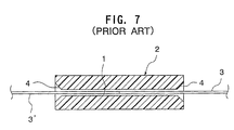
- a conventional optical connector used in this coupling method comprises a coupling member 2 including a given number of small holes 1.
- each of the small holes 1 has an inner diameter of 0.126 mm which is slightly larger than the outer diameter, e.g. 0.125 mm, of an optical fiber wire 3.
- the coupling member 2 is also formed with a guide potion 4 around each periphery of both ends of the small hole 1. The guide portion 4 slants in the direction to widen the small hole 1.
- the optical fiber wires 3, 3' For coupling the optical fiber wires 3, 3' in the above structure, the optical fiber wires 3, 3' each held in a cantilever manner are inserted into the small hole 1 while aligning each of the axes of the optical fiber wires 3, 3' with the axis of the small hole 1 to bring respective one ends of the optical fiber wires 3, 3' into physical contact with each other.
- the conventional optical connector when connecting optical fiber cables, it has been necessary to align the axis of the small hole 1 and the axis of the optical fiber wire 3 with each other.
- the conventional optical connector comes with difficulty aligning the axes with each other because the inner diameter of the small hole 1 is larger than the outer diameter of the optical fiber wire 3 and the optical fiber wire 3 is held in a cantilever manner. This has caused a problem of difficulty in enhancing the coupling accuracy between the optical fiber wires 3, 3'.
- each of associated components is required to have higher dimensional accuracy, resulting in various troubles in manufacturing processes.
- the present invention is directed to solve the above problem. It is therefore an object of the present invention to provide an improved optical connector capable of connecting optical cables readily with enhanced accuracy.
- the present invention provides an optical connector for coupling one optical fiber wire with another optical fiber wire in physical contact.
- the optical connector comprises a receiving portion including a support region adapted to support an optical fiber wire along the axis of the receiving portion.
- the axis of the receiving portion is offset from the axis of the optical fiber wire in a posture of being ready to be inserted into the receiving portion.
- the receiving portion includes a guide region which is provided at the end thereof and on an extension of the axis of the optical fiber wire in the posture of being ready to be inserted into the receiving portion.
- the guide region slants in the direction to widen the receiving portion.
- the support region may be formed in a V-shaped section.
- the inserted optical fiber wire is brought into contact with and bent by the guide region, and then the optical fiber wire is slidably moved along the support region of the receiving portion. Finally, with keeping the optical fiber wire to be supported by the support region, the end of the optical fiber wire is brought into physical contact with the end of another optical fiber wire.
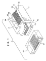
- Fig. 1 shows the major part of an optical connector plug 11, and a coupling member 12 allowing the optical connector plug to be fitted therewith.
- the coupling member 12 is attached to an adapter or receptor (not shown).
- the optical connector plug 11 comprises a seat 13, a sidewall 14 standing upright from each of both sides of the seat 13 and extending in the direction of the fitting movement of the optical connector plug 11, a bottom plate 15 extending horizontally from the lower end beyond the front end of the seat 13, and a visor-like top plate 16 extending in parallel with the bottom plate 15.
- the seat 13 has a top surface higher than that of the bottom plate 15.
- a given number of V-shaped grooves 17 each extending in the direction of the fitting movement of the optical connector plug 11 are formed in the top surface of the seat 13 at even intervals.
- a plurality of optical fiber wires 18 are arrayed and held by each of the V-shaped grooves 17 one by one with extending each front end of the optical fiber wires beyond the seat 13 in a cantilever manner.
- An undercut 19 is formed at the approximately center region of the seat 13 in the direction orthogonal to the V-shaped grooves 17.
- the undercut 19 has a depth greater than that of the V-shaped groove 17.
- a wing wall 20 is formed on the inner surface of the sidewall 14 at a position corresponding to the undercut 19.
- a cover plate made of metal (not shown) is provided over the seat 13 on the rear-end side of the undercut 19 to cover the V-shaped grooves 17.
- the coupling member 12 is formed in a block or square shape, and is fixed within a housing (not shown) of the adapter or receptor.
- a given number of small holes 21 are bored in the coupling member 12 to extend in the direction of the fitting movement of the optical connector plug 11 with forming an array laterally.
- Each axis 24 of the small holes 21 is offset downward from the axis of the corresponding optical fiber wire 18 in a posture of being ready to be inserted into the small hole 21 in question (Fig. 4).
- the small hole 21 is formed in an inverted-triangular-shaped section to provide a support region 22 having a V-shaped section, as shown in Fig. 2.
- a guide region 23 is provided at both ends of the small hole 21. The guide region 23 slants upward and outward.
- the optical fiber wire 18 held by the seat 13 in a cantilever manner is brought into contact with the inclined surface of the guide region 23, and is thereby bent downward along the guide region 23 as shown in Fig. 4 (b). Then, the optical wire 18 bent downward along the guide region 23 is pushed into the support region 22 of the small hole 21, and is slidably moved along the support region 22 to insert the end of the optical fiber wire 18 up to the center region of the small hole 21.
- the coupling member 12 is sandwiched between the bottom plate 15 and the top plate 16 to define the vertical physical relationship between the optical connector plug 11 and the coupling member 12 with reliable accuracy.
- another optical fiber wire 18' is also inserted from another side (the left side of Fig. 4) of the coupling member 12 in the same manner as that described above. Otherwise, when the associated component with which the optical connector plug 11 is fitted is a receptor, another optical fiber wire 18' is disposed along the support region 21 in advance.
- the support region 22 acts to guide the optical fiber wires 18, 18' with supporting the optical fiber wires 18, 18' therealong.
- the sectional shape of the small hole 21 is not limited to the aforementioned inverted triangle, and any other suitable shape, such as a circular shape as shown in Fig. 5, may be used. Further, as shown in Fig. 6, a tapered guide region 27 may be provided around each periphery of both ends of the small hole 26. In this case, when the optical fiber wire 18 is inserted into the coupling member 12, the optical fiber wire 18 is brought into contact with and bent by the guide region 27, and is then supported along a curved region (support region) 28 of the lower portion of the small hole 26.
- the shape of the small hole 21 is not limited to the aforementioned shapes, any other suitable shape capable of serving as a receiving portion having a support region for supporting the optical fiber wire 18 along the axis of the receiving portion may be used.
- adjacent small holes may be integrally formed by partially connecting them, or the small hole may be partially opened to form a groove.
- the offset direction may be any one of upward, horizontal and oblique directions.
- the position of the guide region 23, 27 is varied depending on the offset direction of the axis 24 of the small hole 21, 26.
- the guide region 23, 27 may be provided at any other suitable position (e.g. the right or left side of the small hole 21, 26) located on an extension of the axis 25 of the optical fiber wire 18 in the posture of being ready to be inserted.
- the guide region 23, 37 is not essential. However, in this case, it is desired to provide a tapered surface or a convex surface in the front end of the optical fiber wire 18.
- any other suitable optical connector capable of achieving the physical contact for example a type having a housing surrounding the outer periphery of the optical connector plug 11, may be used.
- the present invention can be applied to a multipolar connector in which a plurality of optical connecters are seriated in parallel with each other.
- the coupling of the optical fiber wires are carried out with keeping the optical fiber wires to be supported along the support region of the receiving portion.
- accurate centering or alignment of the optical fiber wires can be achieved readily and reliably.
- the accurate coupling of the optical fiber wires can be achieved without enhancing dimensional accuracy in associated components. This provides various excellent effects on reduction of manufacturing cost and others.
Landscapes
- Physics & Mathematics (AREA)
- General Physics & Mathematics (AREA)
- Optics & Photonics (AREA)
- Mechanical Coupling Of Light Guides (AREA)
Abstract
Description
Claims (3)
- An optical connector for coupling one optical fiber wire (18) with another optical fiber wire in (18') physical contact, said optical connector comprising a receiving portion (21) including a support region (22) adapted to support an optical fiber wire (18) along the axis (24) of said receiving portion (21), wherein said axis (24) of said receiving portion (21) is offset from the axis (25) of said optical fiber wire (18) in a posture of being ready to be inserted into said receiving portion (21).
- An optical connector as defined in claim 1, wherein said receiving portion (21) includes a guide region (23) which is provided at the end thereof and on an extension (18) of the axis of said optical fiber wire (18) in the posture of being ready to be inserted into said receiving portion (21), said guide region (23) slanting in the direction to widen said receiving portion (21).
- An optical connector as defined in claim 1 or 2, wherein said support region (22) is formed in a V-shaped section.
Applications Claiming Priority (2)
| Application Number | Priority Date | Filing Date | Title |
|---|---|---|---|
| JP2001073613 | 2001-03-15 | ||
| JP2001073613A JP2002277682A (en) | 2001-03-15 | 2001-03-15 | Optical connector |
Publications (2)
| Publication Number | Publication Date |
|---|---|
| EP1241500A2 true EP1241500A2 (en) | 2002-09-18 |
| EP1241500A3 EP1241500A3 (en) | 2002-10-09 |
Family
ID=18931010
Family Applications (1)
| Application Number | Title | Priority Date | Filing Date |
|---|---|---|---|
| EP02005367A Withdrawn EP1241500A3 (en) | 2001-03-15 | 2002-03-14 | Optical fiber connector |
Country Status (3)
| Country | Link |
|---|---|
| US (1) | US6811319B2 (en) |
| EP (1) | EP1241500A3 (en) |
| JP (1) | JP2002277682A (en) |
Cited By (3)
| Publication number | Priority date | Publication date | Assignee | Title |
|---|---|---|---|---|
| WO2003038489A3 (en) * | 2001-10-31 | 2004-06-10 | Corning Cable Sys Llc | Method and apparatus for positioning an optical fiber |
| US7325979B2 (en) | 2003-07-31 | 2008-02-05 | Huber + Suhner Ag | Method for releasably connecting two groups of optical fibers, and plug-in connector for carrying out said method |
| CN103777289A (en) * | 2012-10-19 | 2014-05-07 | 泰科电子(上海)有限公司 | Multi-optical-cable fiber planting method, multi-optical-cable fiber planting device and optical-cable supporting desk |
Families Citing this family (5)
| Publication number | Priority date | Publication date | Assignee | Title |
|---|---|---|---|---|
| US6939120B1 (en) * | 2002-09-12 | 2005-09-06 | Komag, Inc. | Disk alignment apparatus and method for patterned media production |
| JP4576163B2 (en) * | 2004-06-08 | 2010-11-04 | 株式会社巴川製紙所 | Optical connection method |
| JP4639315B2 (en) * | 2006-09-06 | 2011-02-23 | 日本電信電話株式会社 | Optical connector |
| JP5734709B2 (en) * | 2011-03-17 | 2015-06-17 | 富士通株式会社 | Optical connector and electronic information device |
| TWI654456B (en) * | 2016-02-25 | 2019-03-21 | 美商莫仕有限公司 | Waveguide termination module and termination method |
Family Cites Families (9)
| Publication number | Priority date | Publication date | Assignee | Title |
|---|---|---|---|---|
| US3885859A (en) | 1974-06-24 | 1975-05-27 | Northern Electric Co | Optical fibre connectors |
| US3946467A (en) | 1974-12-09 | 1976-03-30 | Northern Electric Company, Limited | Clamp for an optical fibre |
| US4506946A (en) | 1977-09-30 | 1985-03-26 | Trw Inc. | Optic fiber coupling guide, method of making the same and method of use |
| JPS57139716A (en) * | 1981-02-24 | 1982-08-28 | Nippon Telegr & Teleph Corp <Ntt> | Device and method for connection of optical fiber |
| US5155787A (en) * | 1991-09-06 | 1992-10-13 | Minnesota Mining And Manufacturing Company | Multiple optical fiber splice element having ramped porch |
| JPH0743455B2 (en) * | 1991-09-24 | 1995-05-15 | 株式会社精工技研 | Ribbon fiber optic connector |
| US5694506A (en) | 1995-03-09 | 1997-12-02 | Nippon Telegraph And Telephone Corporation | Optical connector |
| JP3312192B2 (en) | 1995-04-25 | 2002-08-05 | 日本航空電子工業株式会社 | Optical fiber holding structure and optical connector |
| JP2001033659A (en) | 1999-07-16 | 2001-02-09 | Japan Aviation Electronics Industry Ltd | Optical connector |
-
2001
- 2001-03-15 JP JP2001073613A patent/JP2002277682A/en active Pending
-
2002
- 2002-03-14 US US10/099,712 patent/US6811319B2/en not_active Expired - Fee Related
- 2002-03-14 EP EP02005367A patent/EP1241500A3/en not_active Withdrawn
Cited By (5)
| Publication number | Priority date | Publication date | Assignee | Title |
|---|---|---|---|---|
| WO2003038489A3 (en) * | 2001-10-31 | 2004-06-10 | Corning Cable Sys Llc | Method and apparatus for positioning an optical fiber |
| US7209375B2 (en) | 2001-10-31 | 2007-04-24 | Corning Cable Systems Llc | Method and apparatus for positioning an optical fiber |
| US7325979B2 (en) | 2003-07-31 | 2008-02-05 | Huber + Suhner Ag | Method for releasably connecting two groups of optical fibers, and plug-in connector for carrying out said method |
| CN103777289A (en) * | 2012-10-19 | 2014-05-07 | 泰科电子(上海)有限公司 | Multi-optical-cable fiber planting method, multi-optical-cable fiber planting device and optical-cable supporting desk |
| CN103777289B (en) * | 2012-10-19 | 2016-12-21 | 泰科电子(上海)有限公司 | Method for fiber planted by many optical cables, many optical cables plant fine equipment and optical cable plummer |
Also Published As
| Publication number | Publication date |
|---|---|
| JP2002277682A (en) | 2002-09-25 |
| US20020131718A1 (en) | 2002-09-19 |
| US6811319B2 (en) | 2004-11-02 |
| EP1241500A3 (en) | 2002-10-09 |
Similar Documents
| Publication | Publication Date | Title |
|---|---|---|
| CN113745872B (en) | Floating connector | |
| CN100385279C (en) | Device for connecting optical cables | |
| US4964812A (en) | Wire termination block | |
| US6840795B1 (en) | Connector | |
| US7896683B1 (en) | Connector assemblies configured to prevent damage to contacts during mating and demating | |
| CN1114116C (en) | Angled mechanical optical connector | |
| JPS6016887Y2 (en) | optical fiber connector | |
| US7245811B2 (en) | Optical connector readily capable of connecting an optical fiber without damaging the optical fiber | |
| WO2000070381A1 (en) | Optical connector assembly using partial large diameter alignment features | |
| EP0043183A1 (en) | Electrical connector for flat cable | |
| EP2051338B1 (en) | Electrical connector assembly | |
| US6811319B2 (en) | Optical connector | |
| KR20020006480A (en) | Alignment system for fiber optic connectors | |
| US4220397A (en) | Optical fiber connector | |
| US20240061187A1 (en) | Multi-fiber ferrule with tapered transition into ferrule bore | |
| JPH061286B2 (en) | Optical fiber connecting device for non-permanent connection between two optical fibers, plug member and holding device used in the device, and optical fiber connecting method | |
| EP0938002B1 (en) | Optical connector | |
| US6872006B2 (en) | Fiber optic cable assembly | |
| JP3312192B2 (en) | Optical fiber holding structure and optical connector | |
| JPH08262275A (en) | Adapter assembly for connector | |
| US20230168438A1 (en) | Fiber optic adapter | |
| US6132235A (en) | Connector lock mechanism | |
| EP1526397A2 (en) | Base for optical element with a fixing wedge | |
| US7093982B1 (en) | Coupling device | |
| US20260003131A1 (en) | Optical connection assembly |
Legal Events
| Date | Code | Title | Description |
|---|---|---|---|
| PUAI | Public reference made under article 153(3) epc to a published international application that has entered the european phase |
Free format text: ORIGINAL CODE: 0009012 |
|
| PUAL | Search report despatched |
Free format text: ORIGINAL CODE: 0009013 |
|
| AK | Designated contracting states |
Kind code of ref document: A2 Designated state(s): AT BE CH CY DE DK ES FI FR GB GR IE IT LI LU MC NL PT SE TR |
|
| AX | Request for extension of the european patent |
Free format text: AL;LT;LV;MK;RO;SI |
|
| AK | Designated contracting states |
Kind code of ref document: A3 Designated state(s): AT BE CH CY DE DK ES FI FR GB GR IE IT LI LU MC NL PT SE TR |
|
| AX | Request for extension of the european patent |
Free format text: AL;LT;LV;MK;RO;SI |
|
| RIN1 | Information on inventor provided before grant (corrected) |
Inventor name: TSUCHIDA, MASAHIRO,HIROSE ELECTRIC CO., LTD. Inventor name: KOBAYASHI, MASARU,NTT INTELL. PROP. CENTER Inventor name: ABE, YOSHITERU,NTT INTELL. PROP. CENTER |
|
| 17P | Request for examination filed |
Effective date: 20030220 |
|
| 17Q | First examination report despatched |
Effective date: 20030513 |
|
| AKX | Designation fees paid |
Designated state(s): DE FR GB IT |
|
| STAA | Information on the status of an ep patent application or granted ep patent |
Free format text: STATUS: THE APPLICATION HAS BEEN WITHDRAWN |
|
| 18W | Application withdrawn |
Effective date: 20041027 |