EP1241454A1 - Weighing scale - Google Patents
Weighing scale Download PDFInfo
- Publication number
- EP1241454A1 EP1241454A1 EP01955693A EP01955693A EP1241454A1 EP 1241454 A1 EP1241454 A1 EP 1241454A1 EP 01955693 A EP01955693 A EP 01955693A EP 01955693 A EP01955693 A EP 01955693A EP 1241454 A1 EP1241454 A1 EP 1241454A1
- Authority
- EP
- European Patent Office
- Prior art keywords
- strain
- plate
- position regulating
- weighing machine
- strain plate
- Prior art date
- Legal status (The legal status is an assumption and is not a legal conclusion. Google has not performed a legal analysis and makes no representation as to the accuracy of the status listed.)
- Withdrawn
Links
Images





Classifications
-
- G—PHYSICS
- G01—MEASURING; TESTING
- G01G—WEIGHING
- G01G23/00—Auxiliary devices for weighing apparatus
- G01G23/06—Means for damping oscillations, e.g. of weigh beams
-
- G—PHYSICS
- G01—MEASURING; TESTING
- G01G—WEIGHING
- G01G19/00—Weighing apparatus or methods adapted for special purposes not provided for in the preceding groups
- G01G19/44—Weighing apparatus or methods adapted for special purposes not provided for in the preceding groups for weighing persons
-
- G—PHYSICS
- G01—MEASURING; TESTING
- G01G—WEIGHING
- G01G21/00—Details of weighing apparatus
- G01G21/23—Support or suspension of weighing platforms
-
- Y—GENERAL TAGGING OF NEW TECHNOLOGICAL DEVELOPMENTS; GENERAL TAGGING OF CROSS-SECTIONAL TECHNOLOGIES SPANNING OVER SEVERAL SECTIONS OF THE IPC; TECHNICAL SUBJECTS COVERED BY FORMER USPC CROSS-REFERENCE ART COLLECTIONS [XRACs] AND DIGESTS
- Y10—TECHNICAL SUBJECTS COVERED BY FORMER USPC
- Y10S—TECHNICAL SUBJECTS COVERED BY FORMER USPC CROSS-REFERENCE ART COLLECTIONS [XRACs] AND DIGESTS
- Y10S177/00—Weighing scales
- Y10S177/09—Scale bearings
Definitions
- the present invention relates to a weighing machine for weighing human bodies and the like.
- a strain plate is strained in a manner such that a load from a scale plate on which an object to be weighed, such as a human body, is placed is transmitted to and concentrated on one point by means of a load transmission mechanism (beam balance) that is formed of a plurality of metal plates combined with one another.
- a load transmission mechanism beam balance
- the change of a resistance value of a strain gauge that is pasted on the strain plate is detected, or the change of capacitance is detected by varying the distance between two electrode plates as the strain plate is displaced, and the change is converted into load.
- metal plates are used in combination with one another in a manner such that they are set upright to stand load from the scale plate, and load transmitting metal plates for transmitting the load from the scale plate to a beam metal plate must be constructed as knife edge fittings, so that the balance normally inevitably has a great thickness of 35 mm or more. Further, knife edge portions are subjected to a very high pressure, so that they are forced to deform and wear away after repeated use, thus failing to ensure long-term reliability.
- a weighing machine 50 is formed in a manner such that a scale plate 51, one strain plate 52, and a base plate 53 are combined in layers.
- the strain plate 52 and the scale plate 51 are fixed in layers with scale plate spacers 54 between them by means of bolts and screws, and the strain plate 52 and the base plate 53 are fixed in layers with base plate spacers 55 between them by means of bolts and screws.
- the base plate 53 is provided with a circuit portion 56, which includes control and arithmetic circuits such as a microcomputer, a display portion 57 for displaying the result of computation, and a power source retaining portion 58, and its plane shape is optional.
- the scale plate 51 in the form of a plate is connected to load receiving portions 59 of the strain plate 52 by means of the scale plate spacers 54.
- the weighing machine 50 is configured to be a weighing machine that is formed of three flat plates and can be made very thin.
- leg portions 60 can be provided on a part of the strain plate 52.
- one or more leg portions 60 provided on the strain plate 52 can be arranged in any other region(s) of outer frames 61 than regions right under fixing portions 62 to which the base plate 53 is fixed.
- hollow portions 63 are formed in the base plate 53.
- the strain plate 52 is formed integrally of a sensitive portion 66 including a strain gauge 65 for use as sensing means, load transmitting beams 64 connecting with the sensitive portion 66, and load receiving portions 59.
- An upper surface 67 of the one strain plate 52 is provided with a center groove portion 68, which includes the sensitive portion 66 and is formed extending parallel to a straight line L-L that connects the respective center points C of the load receiving portions 59.
- a weight applied to the scale plate 51 is received dispersedly by means of the load receiving portions 59, the load is caused to act concentratedly on the sensitive portion 66 by means of the load transmitting beams 64, and strain or deformation of the sensitive portion 66 is picked up as a change of the quantity of electricity by means of the strain gauge 65.
- the load applied to the weighing machine 50 of FIG. 13 acts on the strain plate 52.
- a weighing machine such as a scale that measures a heavy weight
- screw portions for fixing the strain plate 52 and the base plate 53 are liable to loosened by repeated loading. If the screw portions loosen, the position of the strain plate 52 relative to the base plate member is shifted, so that the way the strain plate 52 is strained changes with every measurement. In consequence, measurements of the same weight involve different ways of transmission to the strain gauge 65, inevitably causing measurement errors. Further, a shock of a fall or the like also creates gaps between the strain plate 52 and screws, so that the measurement accuracy lacks in reliability.
- a strain plate and a base plate are fixed by means of the following arrangement instead of screwing.
- a base plate 53 is in the form of an open-topped box
- a strain plate 52 is arranged in the box
- fixing members 70 for preventing vibration and displacement of the strain plate 52 are arranged between the corner portions of the strain plate 52 and a peripheral wall 69 of the base plate 53.
- the object of the present invention is to provide a thin weighing machine of high-reliability, which stands repeated use and whose measurement accuracy is influenced little by a shock of a fall or the like.
- a weighing machine comprises a substantially flat strain plate adapted to be deformed when loaded, a sensor for detecting deformation of the strain plate, a base plate member carrying the strain plate thereon, and a scale plate member located on the upper surface of the strain plate and capable of transmitting load to the strain plate, the sides of the strain plate being held by means of elastic position regulating members, individually.
- the weighing machine according to this aspect can adopt the following forms.
- the strain plate has a strain-direction regulating portion for regulating the direction of a strain produced in the strain plate as the strain plate is deformed.
- the sensor is a strain gauge attached to the strain plate corresponding to the strain direction of the strain plate.
- the position regulating members hold at least the sides of the strain plate which extend at right angles to the strain direction.
- the strain plate is formed with at least two sides extending at right angles to the strain direction and opposed to each other across the strain-direction regulating portion, the two sides being held by means of the position regulating members, individually. Further, the position regulating members hold a plurality of portions of the sides of the strain plate perpendicular to the strain direction. Furthermore, the position regulating members hold two portions near the opposite end portions of the sides of the strain plate perpendicular to the strain direction.
- the position regulating members hold those sides of the strain plate which extend parallel to the strain direction as well as the sides of the strain plate perpendicular to the strain direction.
- the strain plate is formed with a plurality of sides parallel to the strain direction, the sides being held by means of the position regulating members.
- the position regulating members for holding the sides parallel to the strain direction hold portions near the end portions of the sides of the strain plate parallel to the strain direction.
- the strain plate is formed with at least two sides extending at right angles to the strain direction and opposed to each other across the strain-direction regulating portion, and the position regulating members for holding the sides perpendicular to the strain direction hold one portion near the center of each side perpendicular to the strain direction.
- Each of the position regulating members includes a fixed portion fixed to the base plate member and a contact portion formed integrally with the fixed portion and in contact with the side of the strain plate, the contact portion being made elastic by means of a slit formed between the contact portion and the fixed portion.
- Each of the position regulating members is composed of a fixed portion fixed to the base plate member and an elastic portion in contact with the side of the strain plate and attached to the fixed portion.
- the strain plate has two openings in symmetrical positions on the opposite sides of the strain gauge, the position regulating members holding inner walls formed in the openings.
- Each of the position regulating members has a protuberance, the protuberance being in contact with the side of the strain plate.
- the individual sides of the strain plate are arranged so as to be in contact with the position regulating members only.
- the plane shape of the strain plate is substantially rectangular, and the position regulating members are substantially L-shaped members arranged individually near the four corners of the rectangular shape.
- the substantially L-shaped member is formed with a hole portion such that the L-shaped member can be fixed to the scale plate member with the hole portion fitted on a fitting member protruding substantially perpendicularly from the scale plate member.
- the position regulating members for holding the sides of the strain plate perpendicular to the strain direction and the position regulating members for holding the sides of the strain plate parallel to the strain direction are formed separately from one another.
- a weighing machine comprises a substantially flat strain plate adapted to be deformed when loaded, a sensor for detecting deformation of the strain plate, a base plate member carrying the strain plate thereon, and a scale plate member located on the upper surface of the strain plate and capable of transmitting load to the strain plate, the position of the strain plate in the planar direction being settled by means of elastic position regulating members.
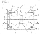
- a weighing machine 1 comprises a strain plate 4, a base plate member 3 on which the strain plate 4 is placed without using fixing means such as screws or bolts, and a scale plate member 2 that is located on the upper surface of the strain plate 4 and serves to transmit load to the strain plate 4.
- the strain plate 4 is formed of one plate member having a substantially rectangular flat surface.
- Load receiving portions 5, which are in the shape of a hemisphere each, are fixed individually to regions near the four corners of the upper surface of the strain plate 4.
- receiving members 2a in the form of a plate are fixed individually to the portions of the lower surface of the scale plate member 2 at the portion facing the load receiving portions 5. Load that is applied to the scale plate member 2 is transmitted to the four load receiving portions 5 of the strain plate 4 through the receiving members 2a.
- the strain plate 4 is formed with grooves that extend straight in its transverse direction (direction perpendicular to line B-B of FIG. 1) in its central portion and form a strain-direction regulating portion 7.
- the grooves of the strain-direction regulating portion 7 are formed individually on the upper and lower surfaces of the strain plate 4, as shown in FIG. 2, one of them may alternatively be formed only on the upper surface of the strain plate 4.
- the grooves (strain-direction regulating portion 7) formed on the strain plate 4 serve to regulate the strain direction of the strain plate 4 to its longitudinal direction (direction B-B of FIG. 1).
- a strain gauge 6 is mounted on the strain plate 4 so as to extend along line B-B of FIG. 1 astride the grooves of the strain-direction regulating portion 7.
- the strain gauge 6 is attached to only the upper surface of the strain plate 4 or each of the upper and lower surfaces.
- the strain gauge 6 senses strain of the strain plate 4 whose strain direction is regulated.
- the central portion of the strain plate 4 where the strain-direction regulating portion 7 is excluded constitute load transmission beams 8 that transmit load on the load receiving portions 5 to the strain gauge 6.
- the four load receiving portions 5 on the strain plate are arranged so as to be symmetrical with respect to the centerline of each groove of the strain-direction regulating portion 7 and also line B-B of FIG. 1.
- Base plate balls 19, which are in the shape of a hemisphere each, are fixed to the lower surface of the strain plate 4 at regions near the four corners thereof, respectively. As shown in FIG. 2, the base plate balls 19 are arranged remoter from the strain-direction regulating portion 7 than the load receiving portions 5 are. In other words, the distance between the base plate balls 19 in the longitudinal direction is greater than the distance between the load receiving portions 5 in the longitudinal direction. However, the distance between the base plate balls 19 in the transverse direction is equal to the distance between the load receiving portions 5 in the transverse direction.
- Receiving members 11 in the shape of a plate are provided on the upper surface of the base plate member 3 at the locations opposite the base plate balls 19 of the strain plate 4.
- leg portions 10 are provided on the lower surface of the base plate member at the locations opposite the receiving members 11.
- the strain plate 4 is supported on the receiving members 11 of the base plate member 3 by means of the base plate balls 19 that are arranged remoter from the strain-direction regulating portion 7 than the load receiving portions 5. If the scale plate member 2 is loaded with an object (human body or the like) to be weighed, it is deformed only in the direction perpendicular to the grooves of the strain-direction regulating portion 7, that is, in the direction of line B-B of FIG. 1.
- the strain gauge 6 detects strain that is attributable to deformation in a portion near the center of the strain plate 4.
- An output signal from the strain gauge 6 is processed in a signal processing circuit (not shown), and a display portion 12 displays the load of the object to be weighed, as shown in FIG. 3.
- number 13 denotes a power switch of the weighing machine 1.
- the strain plate 4 that is placed on the base plate member 3 is held so that its sides C perpendicular to the strain direction B-B are positioned with respect to the base plate member 3 by means of a plurality of elastic position regulating members 14. These position regulating members 14 are attached to the base plate member 3.
- the position regulating members 14 are substantially L-shaped blocks, which are arranged individually in regions near the four corners of the strain plate 4, whereby regions near the end portions of the sides C of the strain plate 4 in the direction perpendicular to the strain direction B-B and regions near the end portions of sides D of the strain plate 4 in the direction parallel to the strain direction B-B are held in position.
- the position regulating member 14 is formed of an L-shaped block of an ABS material or the like. Protuberances 14a that abut against side walls of the strain plate 4 are provided individually on two inner sides of the L-shaped position regulating member 14. Further, the position regulating member 14 is formed with slits 14b having a given length that extend individually inward from its opposite ends, whereby elastic portions 14c capable of elastic deformation are formed ranging form the slits 14b to the inner sides.
- a mounting hole 14d is formed in a part of the position regulating member 14.
- the position regulating member 14 is mounted on the base plate member 3 by fitting a bent portion 3a (see FIG. 1), which is formed by slitting the base plate member 3 at a region near each of the four corners thereof and bending the resulting strip upright, into the mounting hole 14d.
- Each protuberance 14a on the position regulating member 14 substantially has the shape of a semi-cylinder or hemisphere such that the friction of contact with the strain plate 4 is reduced.
- the protuberance is semi-cylindrical, it may be arranged so that the axial direction of the cylinder is in line with the thickness direction of the strain plate, as shown in FIGS. 4A and 4B, or that the axial direction of the cylinder is perpendicular to the thickness direction of the strain plate (not shown).
- the material that constitutes the position regulating member 14 is not limited to the ABS material, and may be any material as far as the elastic portions 14c can resist repeated use.
- FIG. 5A shows a state in which the strain plate 4 is not deformed with no load on the scale plate member 2.
- FIG. 5B shows a state in which the strain plate 4 is deformed with load on the scale plate member 2.
- the strain plate 4 When the strain plate 4 is deformed with a load W on the load receiving portion 5, as shown in FIG. 5B, however, the strain plate 4 is deformed and inclined, so that the side wall on the side C of the strain plate 4 ceases to be in line with the vertical line F, and a part of the strain plate 4 presses the protuberance 14a of the position regulating member 14. If the protuberance 14a of the position regulating member is thus pressed by the strain plate 4, a portion of the strain plate 4 that adjoins the slit is elastically deformed and narrows the slit width of the slit 14b, thereby absorbing the deformation of the strain plate 4.
- the strain plate 4 If the load is removed from the state shown in FIG. 5B, the strain plate 4 is restored to its original flat state by its elasticity, and the side face C of the strain plate 4 is pressed by the protuberance 14a of the position regulating member 14 by the elastic force of the elastic portion 14c of the position regulating member 14, whereupon the strain plate 4 is restored to its original position shown in FIG. 5A.
- the displacement of the strain plate 4 is absorbed by the elastic force of the position regulating member 14, so that no gap is formed between the strain plate 4 and the position regulating member 14 even after repeated use of the weighing machine 1.
- the position regulating member 14 also positions and holds the side D of the strain plate 4 that is parallel to the strain direction B-B as well as the side C of the strain plate 4 that extends at right angles to the strain direction B-B. If any shock attributable to a fall or the like is applied in the direction B-B or the direction perpendicular to B-B, therefore, the position regulating member 14 absorbs the displacement of the strain plate 4, so that the strain plate 4 is restored to its original position. Thus, initial accuracy can be maintained for any length of time.
- the strain plate 4 can be held more steadily by locating the position regulating members 14 in regions near the four corners of the strain plate 4. Since the friction of contact between the strain plate 4 and the position regulating members 14 is minimized by means of the abutting protuberances 14a, furthermore, the accuracy can be maintained for a long period of time without being substantially influenced by repeated use, fall, etc.
- the base plate member 3 is a box-shaped structure that is formed of a rectangular base and side walls set up individually on the four circumferential sides of the base. If there are gaps between the base plate member 3 and the position regulating members 14, as shown in FIG. 1, the peripheral wall of the base plate member 3 may possibly be deformed if the weighing machine 1 is dropped.
- the transverse and longitudinal dimensions of the strain plate 4 with respect to the base plate member 3 are made greater than in the case of FIG. 1 so that no gaps can be created between a peripheral wall 3b of the base plate member 3 and the position regulating members 14 shown in FIG. 4A when the position regulating members 14 are arranged near the four corners of the strain plate 4.
- the position regulating members 14 can restrain the peripheral wall 3b from sinking inward if any external force acts on the peripheral wall 3b of the base plate member 3 when the weighing machine 1 is dropped accidentally.
- creation of the gaps between the peripheral wall 3b of the base plate member 3 and the position regulating members 14 may be prevented by making the width of each position regulating member 14 to be attached to the base plate member 3 greater than in the case of FIG. 1 without changing the size of the strain plate 4 shown in FIG. 1.
- the position regulating members 14 themselves may be sized so that no gaps can be created between the position regulating member 14 and the peripheral wall 3b of the base plate member 3.
- FIGS. 7 and 8 show position regulating members having constructions different from that of the position regulating member 14 shown in FIGS. 4A and 4B.
- a position regulating member 14A shown in FIG. 7 is an L-shaped block that is formed of an ABS material or the like.
- Coil springs 14e are fixed individually to two inner sides of the L-shaped position regulating member 14A.
- One end of each coil spring 14e is fixed to the side face of the position regulating member 14A, while the other end is elastically in contact with the wall surface of the strain plate 4.
- the coil spring 14e combines the respective functions of the protuberance 14a and the elastic portion 14c of the position regulating member 14 shown in FIG. 4A (and therefore, the position regulating member 14A need not be provided with any slit for the formation of the elastic portion).
- the position regulating member 14A is formed with a mounting hole 14d such that the position regulating member 14A can be fixed to the base plate member 3 by fitting the mounting hole 14d on the bent portion 3a (see FIG. 1) of the base plate member 3.
- These coil springs 14e are configured to hold the side D of the strain plate 4 that is parallel to the strain direction B-B as well as the side C of the strain plate 4 that extends at right angles to the strain direction B-B. Accordingly, the same functions as aforesaid can be fulfilled, that is, the position regulating members 14 can absorb the displacement of the strain plate 4 if the weighing machine 1 is used repeatedly or any shock of a fall or the like acts on the strain plate 4. After the load is removed, therefore, the strain plate 4 is restored to its original position, so that the initial accuracy can be maintained for any length of time.
- each leaf spring 14f is molded in an L-shaped wall, while the other end portion is formed with a protuberance 14g that abuts against the side C or the side D of the strain plate 4 extending at right angles or parallel to the strain direction B-B. Further, the position regulating member 14B is provided with a mounting hole 14d. Constructed in this manner, it has the same functions as that of the position regulating member 14A described above.
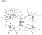
- elastic position regulating members 15 are arranged on sides C of a strain plate 4 that extend at right angles to its strain direction B-B, while fixing members 16 are arranged on sides D of the strain plate 4 that are parallel to the strain direction B-B.
- Each position regulating member 15 is a rectangular block that is formed of an ABS material or the like.
- a protuberance 15a is provided on the side face of the position regulating member 15 which faces a side wall of the strain plate 4.
- the position regulating member 15 comes into contact with a side wall C of the strain plate 4 through its protuberance 15a.
- the position regulating member 15 is formed with a slit 15b with a given length that extends parallel to its side face on which the protuberance 15a is provided, whereby an elastic portion 15c capable of elastic deformation is formed adjacent to the slit 15b.
- a mounting hole 15d is formed in the position regulating member 15, and the position regulating member 15 can be fixed to a base plate member 3 by fitting the mounting hole 15d on a bent portion 3a of the base plate member 3.
- Each fixing member 16 is a rectangular block that is formed of an ABS material or the like.
- a protuberance 16a is provided on the side face of the fixing member 16 which engages a side wall D of the strain plate 4. Thus, the fixing member 16 comes into contact with the side D of the strain plate 4 through its protuberance 16a.
- the fixing member 16 is provided with a mounting hole 16b such that the fixing member 16 can be fixed to the base plate member 3 with the mounting hole 16b fitted on the bent portion 3a of the base plate member 3.
- four position regulating members 15 in total should be arranged opposite the sides C of the strain plate 4 perpendicular to the strain direction B-B and in positions at equal distances from line B-B.
- the position of the strain plate 4 can be kept particularly stable if the position regulating members 15 are arranged near the opposite end portions of the sides C of the strain plate 4.
- four fixing members 16 in total should be arranged near the four end portions of the sides D of the strain plate 4 parallel to the strain direction B-B such that they oppose the sides D.
- the strain plate 4 is deformed to press the protuberances 15a of the position regulating members 15. Thereupon, the portions adjacent to the slits 15b of the position regulating members 15 are elastically deformed to narrow the slit width, thereby absorbing the deformation of the strain plate 4. As this is done, the protuberances 16a of the fixing members 16 are in contact with the side faces D of the strain plate 4 and prevent the strain plate 4 from being dislocated. When the load is removed from the weighing machine 1, the strain plate 4 is restored to its original position by the elastic force of the elastic portions 15d of the position regulating members 15.
- the displacement of the sides C of the strain plate 4 perpendicular to the strain direction B-B, which is attributable to the deformation of the strain plate 4, is absorbed by the elastic position regulating members 15, and the fixing members 16 engage and hold the sides D of the strain plate 4 parallel to the strain direction B-B. Accordingly, dislocation of the strain plate 4 can be prevented and the position of the strain plate 4 never changes if the frequency of use increases, so that the measurement accuracy can be maintained for a long period of time. If the weighing machine 1 is dropped, moreover, a shock that acts in the strain direction of the strain plate 4 can be absorbed.
- a shock that acts in a direction perpendicular to the strain direction of the strain plate 4 when the weighing machine is dropped can be satisfactorily absorbed in a case where the sides D are also positioned and held by means of the elastic position regulating members, as will be described later in connection with a fourth embodiment mentioned.
- one elastic position regulating member 17 is arranged opposite each side C of a strain plate 4 that extends at right angles to its strain direction B-B.
- the position regulating member 17 is a rectangular block that is formed of an elastic member such as a rubber material.
- a protuberance 17a is provided on the side face of the position regulating member 17 which faces a side wall C of the strain plate 4.
- the position regulating member 17 comes into contact with the side C of the strain plate 4 through its protuberance 17a.
- the position regulating member 17 is provided with a mounting hole 17b.
- the position regulating member 17 is fixed to a base plate member 3 with the mounting hole 17b fitted on a bent portion 3a of the base plate member 3.
- fixing members 16 are similar to the ones (fixing members 16 shown in FIG. 9) according to the aforementioned second embodiment, and a description of them is omitted.
- the position regulating member 17 In positioning and holding each side C of the strain plate 4 perpendicular to the strain direction B-B by means of the one position regulating member 17, the position regulating member 17 should preferably be arranged in a position substantially opposite to the center of the side C, as shown in FIG. 9. Further, the fixing members 16 are arranged in the same positions (positions of the fixing members 16 shown in FIG. 9) as those in the case of the second embodiment.
- the displacement of the sides C of the strain plate 4 perpendicular to the strain direction B-B, which is attributable to the deformation of the strain plate 4, is absorbed by means of the elastic position regulating members 17, and the fixing members 16 engage and hold sides D of the strain plate 4 parallel to the strain direction B-B. Accordingly, dislocation of the strain plate 4 can be prevented. Since the position of the strain plate 4 never changes if the frequency of use increases, therefore, the measurement accuracy can be maintained.
- a shock that acts in the strain direction of the strain plate in case of a fall or the like can be absorbed.
- the strain plate 4 is restored to its original position by the elastic force of the rubber material of the position regulating members 17.
- a shock that acts in a direction perpendicular to the strain direction of the strain plate 4 in case of a fall can be satisfactorily absorbed in a case where the sides D are also positioned and held by means of the elastic position regulating members, as will be described later in connection with the fourth embodiment mentioned.
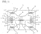
- a strain plate 4 is formed with openings 18 that are arranged on a line in the strain direction B-B of the strain plate 4 in positions symmetrical with respect to the strain gauge 6.
- An elastic position regulating member 17 is arranged opposite an inner wall surface G of each opening 18 that extends at right angles to the strain direction on the side of the strain gauge 6. Further, four elastic position regulating members 17 in total are arranged near the end portions of the sides D of the strain plate 4 parallel to the strain direction B-B such that they oppose the sides D.
- the position regulating members 17 to be arranged in the openings 18 should be arranged in regions where ranges in which force propagates when load is applied are excluded. In other words, they should be arranged as far from straight lines that connect load receiving portions 5 and the strain gauge 6 as possible.
- the six position regulating members 17 shown in FIG. 11 is the same ones as those described in connection with the third embodiment (FIG. 10).
- individual position regulating member 17 comes into contact with the strain plate 4 by means of its protuberance 17a, and is fixed to a base plate member 3 with its mounting hole 17b fitted on a bent portion 3a of the base plate member 3.
- the deformation of the strain plate 4 is absorbed by the elastic position regulating members 17 that are individually in contact with the respective inner wall surfaces G of the openings 18 extending at right angles to the strain direction B-B of the strain plate 4, and the position regulating members 17 are caused to engage the sides D of the strain plate 4 parallel to the strain direction B-B, whereby dislocation of the strain plate 4 is prevented. Since the position of the strain plate 4 never changes if the frequency of use increases, therefore, the measurement accuracy can be maintained.
- a shock caused by a fall of the weighing machine 1 can be absorbed by the six position regulating members 17.
- the strain plate 4 is restored to its original position by means of the elastic force of the rubber material of the position regulating members 17. Since the strain plate 4 is provided with the openings 18, moreover, the strain plate 4 is lightened correspondingly. Further, as the position regulating members 17 are arranged inside the outer wall of the strain plate 4, the external shape can be reduced.
- the four corners of a substantially rectangular strain plate 4 are cut off at an angle of 45° to form four oblique sides H1 and H2, and elastic position regulating members 17 are opposed to the oblique sides H1 and H2 of the strain plate 4, individually.
- the elastic position regulating members 17 are identical with the position regulating members that are used in the third embodiment (FIG. 10) and the fourth embodiment (FIG. 11).
- the position regulating members 17 are arranged opposite the sides H1 and H2 of the strain plate 4 that are inclined at an angle of 45° to the strain direction. Accordingly, the individual position regulating members 17 absorb the displacement of the oblique sides H1 and H2 which is attributable to the deformation of the strain plate 4, by their elasticity, and prevent dislocation of the strain plate 4.
- a shock that is caused by a fall of a weighing machine 1 can be absorbed by elastic deformation of the four position regulating members 17.
- the position regulating members 17 can be reduced from 6 to 4 in number.
- the position regulating members 14, 15 and 17 are provided with the protuberances 14a, 15a and 17a to lessen the friction of contact with the strain plate 4.
- protuberances may be formed on the strain plate 4 without providing the position regulating members with any protuberances.
- the strain plate is positioned and held by means of the elastic position regulating members that are mounted on the base plate member, so that the elasticity of the position regulating members can absorb the displacement of the strain plate that is caused when the strain plate is deformed as the weighing machine is loaded.
- the position regulating members follow the displacement of the strain plate by their elastic force. Even when the weighing machine is not loaded, therefore, the position regulating members are always in contact with the strain plate, so that the position of the strain plate relative to the base plate member that carries it thereon can be kept fixed.
Landscapes
- Physics & Mathematics (AREA)
- General Physics & Mathematics (AREA)
- Measurement Of Force In General (AREA)
- Vehicle Waterproofing, Decoration, And Sanitation Devices (AREA)
Abstract
A strain plate (4) is placed on a base plate
member (3) without using any fixing means. The strain
plate (4) is formed with a straight groove (7) for
restricting its strain direction to one direction. The
base plate member (3) is fitted with position
regulating members (14) opposite the four corner
portions of the strain plate (4), individually. Each
position regulating member (14) is formed with a slit
such that a part of it can be elastically deformed with
ease. The position regulating blocks can absorb the
displacement of the sides of the strain plate that is
caused when the strain plate (4) is deformed as a
weighing machine (1) is loaded.
Description
The present invention relates to a weighing
machine for weighing human bodies and the like.
In a conventional weighing machine, a strain
plate is strained in a manner such that a load from a
scale plate on which an object to be weighed, such as a
human body, is placed is transmitted to and
concentrated on one point by means of a load
transmission mechanism (beam balance) that is formed of
a plurality of metal plates combined with one another.
The change of a resistance value of a strain gauge that
is pasted on the strain plate is detected, or the
change of capacitance is detected by varying the
distance between two electrode plates as the strain
plate is displaced, and the change is converted into
load.
In the beam balance described above, metal plates
are used in combination with one another in a manner
such that they are set upright to stand load from the
scale plate, and load transmitting metal plates for
transmitting the load from the scale plate to a beam
metal plate must be constructed as knife edge fittings,
so that the balance normally inevitably has a great
thickness of 35 mm or more. Further, knife edge
portions are subjected to a very high pressure, so that
they are forced to deform and wear away after repeated
use, thus failing to ensure long-term reliability.
To cope with this, a technique of a thin weighing
machine with simple construction and high long-term
reliability is described in Publication No. WO00/06977,
for example. An outline of this weighing machine will
now be described with reference to FIGS. 13 and 14.
As shown in FIG. 13, a weighing machine 50 is
formed in a manner such that a scale plate 51, one
strain plate 52, and a base plate 53 are combined in
layers. The strain plate 52 and the scale plate 51 are
fixed in layers with scale plate spacers 54 between
them by means of bolts and screws, and the strain plate
52 and the base plate 53 are fixed in layers with base
plate spacers 55 between them by means of bolts and
screws. The base plate 53 is provided with a circuit
portion 56, which includes control and arithmetic
circuits such as a microcomputer, a display portion 57
for displaying the result of computation, and a power
source retaining portion 58, and its plane shape is
optional.
Further, the scale plate 51 in the form of a
plate is connected to load receiving portions 59 of the
strain plate 52 by means of the scale plate spacers 54.
The weighing machine 50 is configured to be a weighing
machine that is formed of three flat plates and can be
made very thin.
In the case where the weighing machine 50 is
placed on a floor surface, leg portions 60 can be
provided on a part of the strain plate 52. For example,
one or more leg portions 60 provided on the strain
plate 52 can be arranged in any other region(s) of
outer frames 61 than regions right under fixing
portions 62 to which the base plate 53 is fixed. To
attain this, hollow portions 63 are formed in the base
plate 53.
The strain plate 52 is formed integrally of a
sensitive portion 66 including a strain gauge 65 for
use as sensing means, load transmitting beams 64
connecting with the sensitive portion 66, and load
receiving portions 59. An upper surface 67 of the one
strain plate 52 is provided with a center groove
portion 68, which includes the sensitive portion 66 and
is formed extending parallel to a straight line L-L
that connects the respective center points C of the
load receiving portions 59. A weight applied to the
scale plate 51 is received dispersedly by means of the
load receiving portions 59, the load is caused to act
concentratedly on the sensitive portion 66 by means of
the load transmitting beams 64, and strain or
deformation of the sensitive portion 66 is picked up as
a change of the quantity of electricity by means of the
strain gauge 65.
The load applied to the weighing machine 50 of
FIG. 13 acts on the strain plate 52. In a weighing
machine such as a scale that measures a heavy weight,
in particular, screw portions for fixing the strain
plate 52 and the base plate 53 are liable to loosened
by repeated loading. If the screw portions loosen, the
position of the strain plate 52 relative to the base
plate member is shifted, so that the way the strain
plate 52 is strained changes with every measurement. In
consequence, measurements of the same weight involve
different ways of transmission to the strain gauge 65,
inevitably causing measurement errors. Further, a shock
of a fall or the like also creates gaps between the
strain plate 52 and screws, so that the measurement
accuracy lacks in reliability.
Another prior art is also described in
Publication No. WO00/06977. In this case, a strain
plate and a base plate are fixed by means of the
following arrangement instead of screwing. As shown in
FIG. 14, a base plate 53 is in the form of an open-topped
box, a strain plate 52 is arranged in the box,
and fixing members 70 for preventing vibration and
displacement of the strain plate 52 are arranged
between the corner portions of the strain plate 52 and
a peripheral wall 69 of the base plate 53.
If sides 70a of the fixing members 70 and sides
52a of the strain plate 52 are brought intimately into
contact with one another, in a weighing machine of the
alternative prior art described above, however, the
central portion of the strain plate 52 sinks during
measurement, and the sides 52a of the strain plate 52
warp, thereby pressing the inner sides 70a of the
fixing members 70. After repeated use, therefore, gaps
are formed between the fixing members 70 and the strain
plate 52, so that the strain plate 52 is dislocated,
and the measurement may possibly be subject to
dispersion, as in the case of the aforesaid screwing
method. If gaps are previously provided between the
fixing members 70 and the strain plate 52 to prevent
this, however, the position of the strain plate 52 is
finely shifted with every measurement, so that
measurement errors may possibly occur. A shock of a
fall or the like also creates gaps between the fixing
members 70 and the strain plate 52, resulting in the
same problem.
The object of the present invention is to provide
a thin weighing machine of high-reliability, which
stands repeated use and whose measurement accuracy is
influenced little by a shock of a fall or the like.
In order to achieve the above object, a weighing
machine according to an aspect of the present invention
comprises a substantially flat strain plate adapted to
be deformed when loaded, a sensor for detecting
deformation of the strain plate, a base plate member
carrying the strain plate thereon, and a scale plate
member located on the upper surface of the strain plate
and capable of transmitting load to the strain plate,
the sides of the strain plate being held by means of
elastic position regulating members, individually.
The weighing machine according to this aspect can
adopt the following forms.
The strain plate has a strain-direction
regulating portion for regulating the direction of a
strain produced in the strain plate as the strain plate
is deformed. The sensor is a strain gauge attached to
the strain plate corresponding to the strain direction
of the strain plate. The position regulating members
hold at least the sides of the strain plate which
extend at right angles to the strain direction.
The strain plate is formed with at least two
sides extending at right angles to the strain direction
and opposed to each other across the strain-direction
regulating portion, the two sides being held by means
of the position regulating members, individually.
Further, the position regulating members hold a
plurality of portions of the sides of the strain plate
perpendicular to the strain direction. Furthermore, the
position regulating members hold two portions near the
opposite end portions of the sides of the strain plate
perpendicular to the strain direction.
The position regulating members hold those sides
of the strain plate which extend parallel to the strain
direction as well as the sides of the strain plate
perpendicular to the strain direction. The strain plate
is formed with a plurality of sides parallel to the
strain direction, the sides being held by means of the
position regulating members. The position regulating
members for holding the sides parallel to the strain
direction hold portions near the end portions of the
sides of the strain plate parallel to the strain
direction.
The strain plate is formed with at least two
sides extending at right angles to the strain direction
and opposed to each other across the strain-direction
regulating portion, and the position regulating members
for holding the sides perpendicular to the strain
direction hold one portion near the center of each side
perpendicular to the strain direction.
Each of the position regulating members includes
a fixed portion fixed to the base plate member and a
contact portion formed integrally with the fixed
portion and in contact with the side of the strain
plate, the contact portion being made elastic by means
of a slit formed between the contact portion and the
fixed portion.
Each of the position regulating members is
composed of a fixed portion fixed to the base plate
member and an elastic portion in contact with the side
of the strain plate and attached to the fixed portion.
The strain plate has two openings in symmetrical
positions on the opposite sides of the strain gauge,
the position regulating members holding inner walls
formed in the openings.
Each of the position regulating members has a
protuberance, the protuberance being in contact with
the side of the strain plate.
The individual sides of the strain plate are
arranged so as to be in contact with the position
regulating members only.
The plane shape of the strain plate is
substantially rectangular, and the position regulating
members are substantially L-shaped members arranged
individually near the four corners of the rectangular
shape. The substantially L-shaped member is formed with
a hole portion such that the L-shaped member can be
fixed to the scale plate member with the hole portion
fitted on a fitting member protruding substantially
perpendicularly from the scale plate member.
The position regulating members for holding the
sides of the strain plate perpendicular to the strain
direction and the position regulating members for
holding the sides of the strain plate parallel to the
strain direction are formed separately from one another.
Further, a weighing machine according to another
aspect of the present invention comprises a
substantially flat strain plate adapted to be deformed
when loaded, a sensor for detecting deformation of the
strain plate, a base plate member carrying the strain
plate thereon, and a scale plate member located on the
upper surface of the strain plate and capable of
transmitting load to the strain plate, the position of
the strain plate in the planar direction being settled
by means of elastic position regulating members.
A first embodiment of the present invention will
be described with reference to FIGS. 1 to 8.
As shown in FIGS. 1 to 3, a weighing machine 1
comprises a strain plate 4, a base plate member 3 on
which the strain plate 4 is placed without using fixing
means such as screws or bolts, and a scale plate member
2 that is located on the upper surface of the strain
plate 4 and serves to transmit load to the strain plate
4.
The strain plate 4 is formed of one plate member
having a substantially rectangular flat surface. Load
receiving portions 5, which are in the shape of a
hemisphere each, are fixed individually to regions near
the four corners of the upper surface of the strain
plate 4. On the other hand, receiving members 2a in the
form of a plate are fixed individually to the portions
of the lower surface of the scale plate member 2 at the
portion facing the load receiving portions 5. Load that
is applied to the scale plate member 2 is transmitted
to the four load receiving portions 5 of the strain
plate 4 through the receiving members 2a.
Further, the strain plate 4 is formed with
grooves that extend straight in its transverse
direction (direction perpendicular to line B-B of FIG.
1) in its central portion and form a strain-direction
regulating portion 7. Although the grooves of the
strain-direction regulating portion 7 are formed
individually on the upper and lower surfaces of the
strain plate 4, as shown in FIG. 2, one of them may
alternatively be formed only on the upper surface of
the strain plate 4. The grooves (strain-direction
regulating portion 7) formed on the strain plate 4
serve to regulate the strain direction of the strain
plate 4 to its longitudinal direction (direction B-B of
FIG. 1).
A strain gauge 6 is mounted on the strain plate 4
so as to extend along line B-B of FIG. 1 astride the
grooves of the strain-direction regulating portion 7.
The strain gauge 6 is attached to only the upper
surface of the strain plate 4 or each of the upper and
lower surfaces. The strain gauge 6 senses strain of the
strain plate 4 whose strain direction is regulated. The
central portion of the strain plate 4 where the strain-direction
regulating portion 7 is excluded constitute
load transmission beams 8 that transmit load on the
load receiving portions 5 to the strain gauge 6.
The four load receiving portions 5 on the strain
plate are arranged so as to be symmetrical with respect
to the centerline of each groove of the strain-direction
regulating portion 7 and also line B-B of FIG.
1.
Base plate balls 19, which are in the shape of a
hemisphere each, are fixed to the lower surface of the
strain plate 4 at regions near the four corners thereof,
respectively. As shown in FIG. 2, the base plate balls
19 are arranged remoter from the strain-direction
regulating portion 7 than the load receiving portions 5
are. In other words, the distance between the base
plate balls 19 in the longitudinal direction is greater
than the distance between the load receiving portions 5
in the longitudinal direction. However, the distance
between the base plate balls 19 in the transverse
direction is equal to the distance between the load
receiving portions 5 in the transverse direction.
Receiving members 11 in the shape of a plate are
provided on the upper surface of the base plate member
3 at the locations opposite the base plate balls 19 of
the strain plate 4. On the other hand, leg portions 10
are provided on the lower surface of the base plate
member at the locations opposite the receiving members
11.
As described above, the strain plate 4 is
supported on the receiving members 11 of the base plate
member 3 by means of the base plate balls 19 that are
arranged remoter from the strain-direction regulating
portion 7 than the load receiving portions 5. If the
scale plate member 2 is loaded with an object (human
body or the like) to be weighed, it is deformed only in
the direction perpendicular to the grooves of the
strain-direction regulating portion 7, that is, in the
direction of line B-B of FIG. 1. The strain gauge 6
detects strain that is attributable to deformation in a
portion near the center of the strain plate 4.
An output signal from the strain gauge 6 is
processed in a signal processing circuit (not shown),
and a display portion 12 displays the load of the
object to be weighed, as shown in FIG. 3. In FIG. 3,
number 13 denotes a power switch of the weighing
machine 1.
As shown in FIG. 1, the strain plate 4 that is
placed on the base plate member 3 is held so that its
sides C perpendicular to the strain direction B-B are
positioned with respect to the base plate member 3 by
means of a plurality of elastic position regulating
members 14. These position regulating members 14 are
attached to the base plate member 3.
The position regulating members 14 are
substantially L-shaped blocks, which are arranged
individually in regions near the four corners of the
strain plate 4, whereby regions near the end portions
of the sides C of the strain plate 4 in the direction
perpendicular to the strain direction B-B and regions
near the end portions of sides D of the strain plate 4
in the direction parallel to the strain direction B-B
are held in position.
The shape of the position regulating member 14
will now be described with reference to the plan view
of FIG. 4A and the side view of FIG. 4B.
The position regulating member 14 is formed of an
L-shaped block of an ABS material or the like.
Protuberances 14a that abut against side walls of the
strain plate 4 are provided individually on two inner
sides of the L-shaped position regulating member 14.
Further, the position regulating member 14 is formed
with slits 14b having a given length that extend
individually inward from its opposite ends, whereby
elastic portions 14c capable of elastic deformation are
formed ranging form the slits 14b to the inner sides.
Furthermore, a mounting hole 14d is formed in a
part of the position regulating member 14. The position
regulating member 14 is mounted on the base plate
member 3 by fitting a bent portion 3a (see FIG. 1),
which is formed by slitting the base plate member 3 at
a region near each of the four corners thereof and
bending the resulting strip upright, into the mounting
hole 14d.
Each protuberance 14a on the position regulating
member 14 substantially has the shape of a semi-cylinder
or hemisphere such that the friction of
contact with the strain plate 4 is reduced. In the case
where the protuberance is semi-cylindrical, it may be
arranged so that the axial direction of the cylinder is
in line with the thickness direction of the strain
plate, as shown in FIGS. 4A and 4B, or that the axial
direction of the cylinder is perpendicular to the
thickness direction of the strain plate (not shown).
The material that constitutes the position
regulating member 14 is not limited to the ABS material,
and may be any material as far as the elastic portions
14c can resist repeated use.
The state of contact between the position
regulating member 14 and the strain plate 4 will now be
described with reference to FIGS. 5A and 5B. FIG. 5A
shows a state in which the strain plate 4 is not
deformed with no load on the scale plate member 2. FIG.
5B shows a state in which the strain plate 4 is
deformed with load on the scale plate member 2.
When the strain plate 4 is not deformed, as shown
in FIG. 5A, the side wall on the side C of the strain
plate 4 that extends at right angles to the strain
direction B-B is in contact with the protuberance 14a
of the position regulating member 14 on a vertical line
indicated by dotted line F.
When the strain plate 4 is deformed with a load W
on the load receiving portion 5, as shown in FIG. 5B,
however, the strain plate 4 is deformed and inclined,
so that the side wall on the side C of the strain plate
4 ceases to be in line with the vertical line F, and a
part of the strain plate 4 presses the protuberance 14a
of the position regulating member 14. If the
protuberance 14a of the position regulating member is
thus pressed by the strain plate 4, a portion of the
strain plate 4 that adjoins the slit is elastically
deformed and narrows the slit width of the slit 14b,
thereby absorbing the deformation of the strain plate 4.
If the load is removed from the state shown in
FIG. 5B, the strain plate 4 is restored to its original
flat state by its elasticity, and the side face C of
the strain plate 4 is pressed by the protuberance 14a
of the position regulating member 14 by the elastic
force of the elastic portion 14c of the position
regulating member 14, whereupon the strain plate 4 is
restored to its original position shown in FIG. 5A.
Thus, the displacement of the strain plate 4 is
absorbed by the elastic force of the position
regulating member 14, so that no gap is formed between
the strain plate 4 and the position regulating member
14 even after repeated use of the weighing machine 1.
Further, the position regulating member 14 also
positions and holds the side D of the strain plate 4
that is parallel to the strain direction B-B as well as
the side C of the strain plate 4 that extends at right
angles to the strain direction B-B. If any shock
attributable to a fall or the like is applied in the
direction B-B or the direction perpendicular to B-B,
therefore, the position regulating member 14 absorbs
the displacement of the strain plate 4, so that the
strain plate 4 is restored to its original position.
Thus, initial accuracy can be maintained for any length
of time.
Further, the strain plate 4 can be held more
steadily by locating the position regulating members 14
in regions near the four corners of the strain plate 4.
Since the friction of contact between the strain plate
4 and the position regulating members 14 is minimized
by means of the abutting protuberances 14a, furthermore,
the accuracy can be maintained for a long period of
time without being substantially influenced by repeated
use, fall, etc.
The base plate member 3 is a box-shaped structure
that is formed of a rectangular base and side walls set
up individually on the four circumferential sides of
the base. If there are gaps between the base plate
member 3 and the position regulating members 14, as
shown in FIG. 1, the peripheral wall of the base plate
member 3 may possibly be deformed if the weighing
machine 1 is dropped.
As shown in FIG. 6A (perspective view) and FIG.
6B (plan view), therefore, the transverse and
longitudinal dimensions of the strain plate 4 with
respect to the base plate member 3 are made greater
than in the case of FIG. 1 so that no gaps can be
created between a peripheral wall 3b of the base plate
member 3 and the position regulating members 14 shown
in FIG. 4A when the position regulating members 14 are
arranged near the four corners of the strain plate 4.
With this arrangement, the position regulating members
14 can restrain the peripheral wall 3b from sinking
inward if any external force acts on the peripheral
wall 3b of the base plate member 3 when the weighing
machine 1 is dropped accidentally. Alternatively,
creation of the gaps between the peripheral wall 3b of
the base plate member 3 and the position regulating
members 14 may be prevented by making the width of each
position regulating member 14 to be attached to the
base plate member 3 greater than in the case of FIG. 1
without changing the size of the strain plate 4 shown
in FIG. 1.
By increasing the transverse and longitudinal
dimensions of the strain plate 4, creation of the gaps
between the peripheral wall 3b of the base plate member
3 and the position regulating members 14 may be
prevented when the position regulating members 14 are
arranged in the regions near the four corners of the
strain plate 4. Alternatively, the position regulating
members 14 themselves may be sized so that no gaps can
be created between the position regulating member 14
and the peripheral wall 3b of the base plate member 3.
FIGS. 7 and 8 show position regulating members
having constructions different from that of the
position regulating member 14 shown in FIGS. 4A and 4B.
A position regulating member 14A shown in FIG. 7
is an L-shaped block that is formed of an ABS material
or the like. Coil springs 14e are fixed individually to
two inner sides of the L-shaped position regulating
member 14A. One end of each coil spring 14e is fixed to
the side face of the position regulating member 14A,
while the other end is elastically in contact with the
wall surface of the strain plate 4. Thus, the coil
spring 14e combines the respective functions of the
protuberance 14a and the elastic portion 14c of the
position regulating member 14 shown in FIG. 4A (and
therefore, the position regulating member 14A need not
be provided with any slit for the formation of the
elastic portion).
Further, the position regulating member 14A is
formed with a mounting hole 14d such that the position
regulating member 14A can be fixed to the base plate
member 3 by fitting the mounting hole 14d on the bent
portion 3a (see FIG. 1) of the base plate member 3.
These coil springs 14e are configured to hold the
side D of the strain plate 4 that is parallel to the
strain direction B-B as well as the side C of the
strain plate 4 that extends at right angles to the
strain direction B-B. Accordingly, the same functions
as aforesaid can be fulfilled, that is, the position
regulating members 14 can absorb the displacement of
the strain plate 4 if the weighing machine 1 is used
repeatedly or any shock of a fall or the like acts on
the strain plate 4. After the load is removed,
therefore, the strain plate 4 is restored to its
original position, so that the initial accuracy can be
maintained for any length of time.
In a position regulating member 14B shown in FIG.
8, leaf springs 14f are used in place of the coil
springs 14e of the position regulating member 14A
described above. One end portion of each leaf spring
14f is molded in an L-shaped wall, while the other end
portion is formed with a protuberance 14g that abuts
against the side C or the side D of the strain plate 4
extending at right angles or parallel to the strain
direction B-B. Further, the position regulating member
14B is provided with a mounting hole 14d. Constructed
in this manner, it has the same functions as that of
the position regulating member 14A described above.
A second embodiment of the present invention will
now be described with reference to FIG. 9.
In this embodiment, elastic position regulating
members 15 are arranged on sides C of a strain plate 4
that extend at right angles to its strain direction B-B,
while fixing members 16 are arranged on sides D of the
strain plate 4 that are parallel to the strain
direction B-B.
Each position regulating member 15 is a
rectangular block that is formed of an ABS material or
the like. A protuberance 15a is provided on the side
face of the position regulating member 15 which faces a
side wall of the strain plate 4. Thus, the position
regulating member 15 comes into contact with a side
wall C of the strain plate 4 through its protuberance
15a. The position regulating member 15 is formed with a
slit 15b with a given length that extends parallel to
its side face on which the protuberance 15a is provided,
whereby an elastic portion 15c capable of elastic
deformation is formed adjacent to the slit 15b.
Further, a mounting hole 15d is formed in the
position regulating member 15, and the position
regulating member 15 can be fixed to a base plate
member 3 by fitting the mounting hole 15d on a bent
portion 3a of the base plate member 3.
Each fixing member 16 is a rectangular block that
is formed of an ABS material or the like. A
protuberance 16a is provided on the side face of the
fixing member 16 which engages a side wall D of the
strain plate 4. Thus, the fixing member 16 comes into
contact with the side D of the strain plate 4 through
its protuberance 16a. Further, the fixing member 16 is
provided with a mounting hole 16b such that the fixing
member 16 can be fixed to the base plate member 3 with
the mounting hole 16b fitted on the bent portion 3a of
the base plate member 3.
Preferably, four position regulating members 15
in total should be arranged opposite the sides C of the
strain plate 4 perpendicular to the strain direction B-B
and in positions at equal distances from line B-B.
The position of the strain plate 4 can be kept
particularly stable if the position regulating members
15 are arranged near the opposite end portions of the
sides C of the strain plate 4. Further, four fixing
members 16 in total should be arranged near the four
end portions of the sides D of the strain plate 4
parallel to the strain direction B-B such that they
oppose the sides D.
If a load is applied to a weighing machine 1
shown in FIG. 9, the strain plate 4 is deformed to
press the protuberances 15a of the position regulating
members 15. Thereupon, the portions adjacent to the
slits 15b of the position regulating members 15 are
elastically deformed to narrow the slit width, thereby
absorbing the deformation of the strain plate 4. As
this is done, the protuberances 16a of the fixing
members 16 are in contact with the side faces D of the
strain plate 4 and prevent the strain plate 4 from
being dislocated. When the load is removed from the
weighing machine 1, the strain plate 4 is restored to
its original position by the elastic force of the
elastic portions 15d of the position regulating members
15.
In the weighing machine 1 shown in FIG. 9, the
displacement of the sides C of the strain plate 4
perpendicular to the strain direction B-B, which is
attributable to the deformation of the strain plate 4,
is absorbed by the elastic position regulating members
15, and the fixing members 16 engage and hold the sides
D of the strain plate 4 parallel to the strain
direction B-B. Accordingly, dislocation of the strain
plate 4 can be prevented and the position of the strain
plate 4 never changes if the frequency of use increases,
so that the measurement accuracy can be maintained for
a long period of time. If the weighing machine 1 is
dropped, moreover, a shock that acts in the strain
direction of the strain plate 4 can be absorbed. A
shock that acts in a direction perpendicular to the
strain direction of the strain plate 4 when the
weighing machine is dropped can be satisfactorily
absorbed in a case where the sides D are also
positioned and held by means of the elastic position
regulating members, as will be described later in
connection with a fourth embodiment mentioned.
A third embodiment of the present invention will
now be described with reference to FIG. 10.
In this embodiment, one elastic position
regulating member 17 is arranged opposite each side C
of a strain plate 4 that extends at right angles to its
strain direction B-B.
The position regulating member 17 is a
rectangular block that is formed of an elastic member
such as a rubber material. A protuberance 17a is
provided on the side face of the position regulating
member 17 which faces a side wall C of the strain plate
4. Thus, the position regulating member 17 comes into
contact with the side C of the strain plate 4 through
its protuberance 17a. Further, the position regulating
member 17 is provided with a mounting hole 17b. The
position regulating member 17 is fixed to a base plate
member 3 with the mounting hole 17b fitted on a bent
portion 3a of the base plate member 3.
Since fixing members 16 are similar to the ones
(fixing members 16 shown in FIG. 9) according to the
aforementioned second embodiment, and a description of
them is omitted.
In positioning and holding each side C of the
strain plate 4 perpendicular to the strain direction B-B
by means of the one position regulating member 17,
the position regulating member 17 should preferably be
arranged in a position substantially opposite to the
center of the side C, as shown in FIG. 9. Further, the
fixing members 16 are arranged in the same positions
(positions of the fixing members 16 shown in FIG. 9) as
those in the case of the second embodiment.
In a weighing machine 1 shown in FIG. 10, the
displacement of the sides C of the strain plate 4
perpendicular to the strain direction B-B, which is
attributable to the deformation of the strain plate 4,
is absorbed by means of the elastic position regulating
members 17, and the fixing members 16 engage and hold
sides D of the strain plate 4 parallel to the strain
direction B-B. Accordingly, dislocation of the strain
plate 4 can be prevented. Since the position of the
strain plate 4 never changes if the frequency of use
increases, therefore, the measurement accuracy can be
maintained.
Further, a shock that acts in the strain
direction of the strain plate in case of a fall or the
like can be absorbed. When the load is removed from the
weighing machine 1, the strain plate 4 is restored to
its original position by the elastic force of the
rubber material of the position regulating members 17.
A shock that acts in a direction perpendicular to the
strain direction of the strain plate 4 in case of a
fall can be satisfactorily absorbed in a case where the
sides D are also positioned and held by means of the
elastic position regulating members, as will be
described later in connection with the fourth
embodiment mentioned.
The fourth embodiment of the present invention
will now be described with reference to FIG. 11.
In this embodiment, a strain plate 4 is formed
with openings 18 that are arranged on a line in the
strain direction B-B of the strain plate 4 in positions
symmetrical with respect to the strain gauge 6. An
elastic position regulating member 17 is arranged
opposite an inner wall surface G of each opening 18
that extends at right angles to the strain direction on
the side of the strain gauge 6. Further, four elastic
position regulating members 17 in total are arranged
near the end portions of the sides D of the strain
plate 4 parallel to the strain direction B-B such that
they oppose the sides D.
Preferably, the position regulating members 17 to
be arranged in the openings 18 should be arranged in
regions where ranges in which force propagates when
load is applied are excluded. In other words, they
should be arranged as far from straight lines that
connect load receiving portions 5 and the strain gauge
6 as possible.
The six position regulating members 17 shown in
FIG. 11 is the same ones as those described in
connection with the third embodiment (FIG. 10). Thus,
individual position regulating member 17 comes into
contact with the strain plate 4 by means of its
protuberance 17a, and is fixed to a base plate member 3
with its mounting hole 17b fitted on a bent portion 3a
of the base plate member 3.
In a weighing machine 1 shown in FIG. 11, the
deformation of the strain plate 4 is absorbed by the
elastic position regulating members 17 that are
individually in contact with the respective inner wall
surfaces G of the openings 18 extending at right angles
to the strain direction B-B of the strain plate 4, and
the position regulating members 17 are caused to engage
the sides D of the strain plate 4 parallel to the
strain direction B-B, whereby dislocation of the strain
plate 4 is prevented. Since the position of the strain
plate 4 never changes if the frequency of use increases,
therefore, the measurement accuracy can be maintained.
Further, a shock caused by a fall of the weighing
machine 1 can be absorbed by the six position
regulating members 17. When the load is removed from
the weighing machine 1, the strain plate 4 is restored
to its original position by means of the elastic force
of the rubber material of the position regulating
members 17. Since the strain plate 4 is provided with
the openings 18, moreover, the strain plate 4 is
lightened correspondingly. Further, as the position
regulating members 17 are arranged inside the outer
wall of the strain plate 4, the external shape can be
reduced.
A fifth embodiment of the present invention will
now be described with reference to FIG. 12.
In this embodiment, the four corners of a
substantially rectangular strain plate 4 are cut off at
an angle of 45° to form four oblique sides H1 and H2,
and elastic position regulating members 17 are opposed
to the oblique sides H1 and H2 of the strain plate 4,
individually.
The elastic position regulating members 17 are
identical with the position regulating members that are
used in the third embodiment (FIG. 10) and the fourth
embodiment (FIG. 11).
The position regulating members 17 are arranged
opposite the sides H1 and H2 of the strain plate 4 that
are inclined at an angle of 45° to the strain direction.
Accordingly, the individual position regulating members
17 absorb the displacement of the oblique sides H1 and
H2 which is attributable to the deformation of the
strain plate 4, by their elasticity, and prevent
dislocation of the strain plate 4.
Further, a shock that is caused by a fall of a
weighing machine 1 can be absorbed by elastic
deformation of the four position regulating members 17.
According to the weighing machine 1 of FIG. 12,
compared with fourth embodiment, the position
regulating members 17 can be reduced from 6 to 4 in
number.
In the first to fifth embodiments of the present
invention, the position regulating members 14, 15 and
17 are provided with the protuberances 14a, 15a and 17a
to lessen the friction of contact with the strain plate
4. Alternatively, however, protuberances may be formed
on the strain plate 4 without providing the position
regulating members with any protuberances.
In the weighing machine according to the present
invention, the strain plate is positioned and held by
means of the elastic position regulating members that
are mounted on the base plate member, so that the
elasticity of the position regulating members can
absorb the displacement of the strain plate that is
caused when the strain plate is deformed as the
weighing machine is loaded. When the strain plate is
restored to its original state after the load is
removed from the weighing machine, the position
regulating members follow the displacement of the
strain plate by their elastic force. Even when the
weighing machine is not loaded, therefore, the position
regulating members are always in contact with the
strain plate, so that the position of the strain plate
relative to the base plate member that carries it
thereon can be kept fixed.
Claims (24)
- A weighing machine comprising a substantially flat strain plate adapted to be deformed when loaded, a sensor for detecting deformation of said strain plate, a base plate member carrying said strain plate thereon, and a scale plate member located on the upper surface of said strain plate and capable of transmitting load to said strain plate, wherein
the sides of said strain plate are held by means of elastic position regulating members, individually. - The weighing machine according to claim 1, wherein said strain plate has a strain-direction regulating portion for regulating the direction of a strain produced in said strain plate as said strain plate is deformed, said sensor is a strain gauge attached to said strain plate corresponding to the strain direction of said strain plate, and said position regulating members hold at least the sides of said strain plate which extend at right angles to said strain direction.
- The weighing machine according to claim 2, wherein said strain plate is formed with at least two sides extending at right angles to said strain direction, opposed to each other across said strain-direction regulating portion, and said two sides are held by said position regulating members, individually.
- The weighing machine according to claim 3, wherein said position regulating members for holding the sides perpendicular to said strain direction hold the sides of said strain plate perpendicular to said strain direction at a plurality of portions thereof.
- The weighing machine according to claim 4, wherein said position regulating members for holding the sides perpendicular to said strain direction hold the sides of said strain plate perpendicular to said strain direction at two portions near the opposite end portions thereof.
- The weighing machine according to claim 2, wherein said position regulating members hold the sides of said strain plate which extend parallel to said strain direction as well as the sides of said strain plate perpendicular to the strain direction.
- The weighing machine according to claim 6, wherein said strain plate is formed with a plurality of sides parallel to said strain direction, and said plurality of sides are held by means of said position regulating members.
- The weighing machine according to claim 7, wherein said position regulating members for holding the sides parallel to said strain direction hold the sides of said strain plate parallel to said strain direction at portions near the end portions thereof.
- The weighing machine according to claim 7, wherein said strain plate is formed with at least two sides extending at right angles to said strain direction and opposed to each other across said strain-direction regulating portion, and said position regulating members for holding the sides perpendicular to said strain direction hold the sides perpendicular to said strain direction at one portion near the center thereof, respectively.
- The weighing machine according to claim 1, wherein each said position regulating member includes a fixed portion fixed to said base plate member and a contact portion formed integrally with said fixed portion and in contact with the side of said strain plate, and said contact portion is made elastic by a slit formed between said contact portion and said fixed portion.
- The weighing machine according to claim 1, wherein each said position regulating member is composed of a fixed portion fixed to said base plate member and an elastic portion in contact with the side of said strain plate and attached to said fixed portion.
- The weighing machine according to claim 2, wherein said strain plate has two openings in positions symmetrical with respect to the strain gauge, and said position regulating members hold the inner walls formed in said openings.
- The weighing machine according to claim 1, wherein each said position regulating member has a protuberance, and said protuberance is in contact with the side of said strain plate.
- The weighing machine according to claim 1, wherein the individual sides of said strain plate are arranged so as to be in contact with said position regulating members only.
- The weighing machine according to claim 6, wherein the plane shape of said strain plate is substantially rectangular, and said position regulating members are substantially L-shaped members arranged individually near the four corners of said rectangular shape.
- The weighing machine according to claim 15, wherein said substantially L-shaped member is formed with a hole portion such that the L-shaped member can be fixed to said base plate member with said hole portion fitted on a fitting member protruding substantially perpendicularly from said base plate member.
- The weighing machine according to claim 6, wherein said position regulating members for holding the sides of said strain plate perpendicular to the strain direction and said position regulating members for holding the sides of said strain plate parallel to the strain direction are formed separately from one another.
- The weighing machine comprising a substantially flat strain plate adapted to be deformed when loaded, a sensor for detecting deformation of said strain plate, a base plate member carrying said strain plate thereon, and a scale plate member located on the upper surface of said strain plate and capable of transmitting load to said strain plate, wherein
the position of said strain plate in the planar direction is settled by means of elastic position regulating members. - The weighing machine according to claim 15, wherein the portion of said L-shaped member which faces a side of said strain plate perpendicular to the strain direction is provided with a slit extending parallel to the side perpendicular to said strain direction, and the portion of said L-shaped member which faces a side of said strain plate parallel to the strain direction is provided with a slit extending parallel to the side parallel to said strain direction, whereby said L-shaped member is made elastic.
- The weighing machine according to claim 13, wherein said protuberance is in the shape of a semi-cylinder or hemisphere.
- The weighing machine according to claim 16, wherein said fitting member is formed by slitting and raising a part of said base plate member.
- The weighing machine according to claim 15, wherein said base plate member has side walls set up thereon, and the size of said position regulating members is regulated such that gap be not formed between said side wall and said position regulating member.
- The weighing machine according to claim 1, wherein said position regulating members are formed of an elastic material such as rubber.
- The weighing machine according to claim 1, wherein said strain plate is formed with a straight groove for regulating the direction of a strain formed as said strain plate is deformed, said strain plate has oblique sides inclined at about 45° to the direction of said groove, and said oblique sides are held by means of said position regulating members, individually.
Applications Claiming Priority (3)
| Application Number | Priority Date | Filing Date | Title |
|---|---|---|---|
| JP2000246179 | 2000-08-15 | ||
| JP2000246179 | 2000-08-15 | ||
| PCT/JP2001/006971 WO2002014807A1 (en) | 2000-08-15 | 2001-08-13 | Weighing scale |
Publications (2)
| Publication Number | Publication Date |
|---|---|
| EP1241454A1 true EP1241454A1 (en) | 2002-09-18 |
| EP1241454A4 EP1241454A4 (en) | 2003-05-21 |
Family
ID=18736547
Family Applications (1)
| Application Number | Title | Priority Date | Filing Date |
|---|---|---|---|
| EP01955693A Withdrawn EP1241454A4 (en) | 2000-08-15 | 2001-08-13 | Weighing scale |
Country Status (8)
| Country | Link |
|---|---|
| US (1) | US6812414B2 (en) |
| EP (1) | EP1241454A4 (en) |
| KR (1) | KR20020040862A (en) |
| CN (1) | CN1233994C (en) |
| AU (1) | AU7777701A (en) |
| CA (1) | CA2387086A1 (en) |
| TW (1) | TW503309B (en) |
| WO (1) | WO2002014807A1 (en) |
Families Citing this family (22)
| Publication number | Priority date | Publication date | Assignee | Title |
|---|---|---|---|---|
| US7235746B2 (en) * | 2005-03-09 | 2007-06-26 | Metro Corporation | Modular apparatus for electronic scales and a method for assembling same |
| US7214892B2 (en) * | 2005-03-15 | 2007-05-08 | Metro Corporation | Scale lever assembly |
| JP4486025B2 (en) * | 2005-11-15 | 2010-06-23 | アルプス電気株式会社 | Load sensor |
| US7554043B2 (en) * | 2007-05-03 | 2009-06-30 | Edlund Company, Inc. | Weighing scale having dual housings |
| US7504594B1 (en) | 2007-10-05 | 2009-03-17 | Nucor Corporation | Steel coil weighing apparatus and method for use thereof |
| EP2434265B1 (en) * | 2010-09-22 | 2014-03-05 | Wipotec Wiege- und Positioniersysteme GmbH | Weighing device with thermal decoupling |
| CN102322929A (en) * | 2011-09-22 | 2012-01-18 | 福州祥杰电子有限公司 | Single-capacitor type weighing scale |
| US9526451B1 (en) | 2012-01-11 | 2016-12-27 | Bertec Corporation | Force measurement system |
| US8915149B1 (en) | 2012-01-11 | 2014-12-23 | Bertec Corporation | Force measurement system |
| US8544347B1 (en) * | 2012-01-11 | 2013-10-01 | Bertec Corporation | Force measurement system having a plurality of measurement surfaces |
| US9168420B1 (en) | 2012-01-11 | 2015-10-27 | Bertec Corporation | Force measurement system |
| USD689388S1 (en) * | 2013-04-12 | 2013-09-10 | Bertec Corporation | Dual force plate |
| USD689389S1 (en) * | 2013-04-12 | 2013-09-10 | Bertec Corporation | Dual force plate |
| WO2016011625A1 (en) * | 2014-07-23 | 2016-01-28 | 王雅苹 | Electronic scale |
| CN104977075A (en) * | 2015-07-23 | 2015-10-14 | 刘海萍 | Weight scale suitable for wild use |
| US10309823B2 (en) * | 2016-01-08 | 2019-06-04 | Withings | Thin weighing scale with a sandwich structure |
| KR101804297B1 (en) | 2016-02-23 | 2017-12-04 | (주)아이투에이시스템즈 | Force sensor using displacement amplification mechanism and apparatus for measuring weight having the same |
| CN106679784A (en) * | 2017-01-04 | 2017-05-17 | 缤刻普锐(北京)科技有限责任公司 | Electronic weighing device without scale feet |
| JP6999586B2 (en) * | 2019-01-28 | 2022-01-18 | 日本電産コパル電子株式会社 | Elastic body and force sensor using it |
| USD938845S1 (en) * | 2019-10-07 | 2021-12-21 | Cas Corporation | Road weigher for vehicle |
| USD938846S1 (en) * | 2019-10-07 | 2021-12-21 | Cas Corporation | Road weigher for vehicle |
| CN112665699B (en) * | 2020-11-23 | 2022-03-04 | 超越工场(东莞)科技有限公司 | Three-dimensional measurement and calculation method for high-precision weight scale |
Family Cites Families (11)
| Publication number | Priority date | Publication date | Assignee | Title |
|---|---|---|---|---|
| US4411327A (en) * | 1981-05-14 | 1983-10-25 | Hottinger Baldwin Measurements, Inc. | Apparatus for applying a load to a strain gage transducer beam |
| US4554987A (en) * | 1983-08-29 | 1985-11-26 | Dillon Benny N | Self-aligning scale assembly and method |
| US4483404A (en) * | 1983-08-30 | 1984-11-20 | Benny N. Dillon | Self-aligning scale assembly |
| JPS61116621A (en) | 1984-09-17 | 1986-06-04 | エスタブレシミエント メタルルジコ ノルメタル エス・エイ・シ−・アイ・エフ・イ−・アイ・ | Dynamometer |
| US4611678A (en) * | 1984-11-07 | 1986-09-16 | Andriewsky Miguel S | Heavy duty weighing machine having high precision and resolution features |
| JPH0348501Y2 (en) * | 1985-12-19 | 1991-10-16 | ||
| FR2608759B1 (en) | 1986-12-19 | 1995-05-05 | Dal Dan Felice | SCALE OF THE GENDER SCALE |
| JPS6443729A (en) | 1987-08-11 | 1989-02-16 | Teraoka Seiko Kk | Thin type balance |
| US4899840A (en) * | 1989-06-22 | 1990-02-13 | Boubille Jacques C | Apparatus for weighing a pallet with a load thereon for use with a vehicle having tines or the like |
| JPH0348501A (en) | 1989-07-17 | 1991-03-01 | Kyocera Corp | Rectangular waveguide |
| US5425278A (en) * | 1993-09-17 | 1995-06-20 | Pneumatic Scale Corporation | Weigh scale with sapphire load cell |
-
2001
- 2001-08-13 WO PCT/JP2001/006971 patent/WO2002014807A1/en not_active Ceased
- 2001-08-13 US US10/110,468 patent/US6812414B2/en not_active Expired - Fee Related
- 2001-08-13 AU AU77777/01A patent/AU7777701A/en not_active Abandoned
- 2001-08-13 KR KR1020027004732A patent/KR20020040862A/en not_active Withdrawn
- 2001-08-13 CA CA002387086A patent/CA2387086A1/en not_active Abandoned
- 2001-08-13 CN CNB018021921A patent/CN1233994C/en not_active Expired - Fee Related
- 2001-08-13 EP EP01955693A patent/EP1241454A4/en not_active Withdrawn
- 2001-08-14 TW TW090119849A patent/TW503309B/en not_active IP Right Cessation
Also Published As
| Publication number | Publication date |
|---|---|
| KR20020040862A (en) | 2002-05-30 |
| CN1233994C (en) | 2005-12-28 |
| US6812414B2 (en) | 2004-11-02 |
| TW503309B (en) | 2002-09-21 |
| WO2002014807A1 (en) | 2002-02-21 |
| AU7777701A (en) | 2002-02-25 |
| US20020148653A1 (en) | 2002-10-17 |
| CA2387086A1 (en) | 2002-02-21 |
| EP1241454A4 (en) | 2003-05-21 |
| CN1386192A (en) | 2002-12-18 |
Similar Documents
| Publication | Publication Date | Title |
|---|---|---|
| US6812414B2 (en) | Weighing scale | |
| EP0771410B1 (en) | A mass-produced flat multiple-beam load cell and scales incorporating it | |
| EP0505493B1 (en) | A mass-produced flat one-piece load cell and scales incorporating it | |
| US5440077A (en) | Combined weighting and displacement sensor and weighing apparatus using the same | |
| US7210362B2 (en) | Diaphragm type load detection sensor, load detection unit and electronic scale using same | |
| JP3423578B2 (en) | Impact protection device for force measurement device | |
| JP4028785B2 (en) | Load detection unit and electronic scale using the same | |
| JP6016937B2 (en) | Load cell | |
| CN104075782A (en) | Flexure element, load cell, and weight measuring device | |
| US20180306655A1 (en) | Component transducer and multi-component transducer using such component transducer as well as use of such multi-component transducer | |
| GB2528897A (en) | Low-profile load cell assembly | |
| WO2000075617A1 (en) | Load cell | |
| US7070332B2 (en) | Combination of bearing housing and load measuring plate | |
| WO1985001796A1 (en) | Weight scales and strain gauge assemblies useable therein | |
| JPH0229179B2 (en) | DENSHIBAKARI | |
| JP2004045138A (en) | Force transducer | |
| KR20010024325A (en) | Weighing Machine | |
| JP7537731B2 (en) | Force Transducer | |
| JPWO2002014807A1 (en) | weighing scale | |
| JP5611793B2 (en) | Load cell | |
| US7093506B2 (en) | Force measurement cell | |
| JPH0649970U (en) | Focus on multi-point weighing scale | |
| JPH059625Y2 (en) | ||
| JP3823886B2 (en) | Electronic balance | |
| JP2005017061A (en) | Load cell |
Legal Events
| Date | Code | Title | Description |
|---|---|---|---|
| PUAI | Public reference made under article 153(3) epc to a published international application that has entered the european phase |
Free format text: ORIGINAL CODE: 0009012 |
|
| 17P | Request for examination filed |
Effective date: 20020415 |
|
| AK | Designated contracting states |
Kind code of ref document: A1 Designated state(s): AT BE CH CY DE DK ES FI FR GB GR IE IT LI LU MC NL PT SE TR |
|
| A4 | Supplementary search report drawn up and despatched |
Effective date: 20030403 |
|
| STAA | Information on the status of an ep patent application or granted ep patent |
Free format text: STATUS: THE APPLICATION IS DEEMED TO BE WITHDRAWN |
|
| 18D | Application deemed to be withdrawn |
Effective date: 20040302 |