EP1241344A2 - Luftansaugkanalsystem für eine Brennkraftmaschine - Google Patents
Luftansaugkanalsystem für eine Brennkraftmaschine Download PDFInfo
- Publication number
- EP1241344A2 EP1241344A2 EP02001834A EP02001834A EP1241344A2 EP 1241344 A2 EP1241344 A2 EP 1241344A2 EP 02001834 A EP02001834 A EP 02001834A EP 02001834 A EP02001834 A EP 02001834A EP 1241344 A2 EP1241344 A2 EP 1241344A2
- Authority
- EP
- European Patent Office
- Prior art keywords
- air intake
- housing part
- duct system
- intake duct
- shaft
- Prior art date
- Legal status (The legal status is an assumption and is not a legal conclusion. Google has not performed a legal analysis and makes no representation as to the accuracy of the status listed.)
- Withdrawn
Links
Images

Classifications
-
- F—MECHANICAL ENGINEERING; LIGHTING; HEATING; WEAPONS; BLASTING
- F02—COMBUSTION ENGINES; HOT-GAS OR COMBUSTION-PRODUCT ENGINE PLANTS
- F02M—SUPPLYING COMBUSTION ENGINES IN GENERAL WITH COMBUSTIBLE MIXTURES OR CONSTITUENTS THEREOF
- F02M35/00—Combustion-air cleaners, air intakes, intake silencers, or induction systems specially adapted for, or arranged on, internal-combustion engines
- F02M35/10—Air intakes; Induction systems
- F02M35/10006—Air intakes; Induction systems characterised by the position of elements of the air intake system in direction of the air intake flow, i.e. between ambient air inlet and supply to the combustion chamber
- F02M35/10078—Connections of intake systems to the engine
-
- F—MECHANICAL ENGINEERING; LIGHTING; HEATING; WEAPONS; BLASTING
- F02—COMBUSTION ENGINES; HOT-GAS OR COMBUSTION-PRODUCT ENGINE PLANTS
- F02B—INTERNAL-COMBUSTION PISTON ENGINES; COMBUSTION ENGINES IN GENERAL
- F02B31/00—Modifying induction systems for imparting a rotation to the charge in the cylinder
- F02B31/08—Modifying induction systems for imparting a rotation to the charge in the cylinder having multiple air inlets
- F02B31/085—Modifying induction systems for imparting a rotation to the charge in the cylinder having multiple air inlets having two inlet valves
-
- F—MECHANICAL ENGINEERING; LIGHTING; HEATING; WEAPONS; BLASTING
- F02—COMBUSTION ENGINES; HOT-GAS OR COMBUSTION-PRODUCT ENGINE PLANTS
- F02D—CONTROLLING COMBUSTION ENGINES
- F02D9/00—Controlling engines by throttling air or fuel-and-air induction conduits or exhaust conduits
- F02D9/08—Throttle valves specially adapted therefor; Arrangements of such valves in conduits
- F02D9/10—Throttle valves specially adapted therefor; Arrangements of such valves in conduits having pivotally-mounted flaps
- F02D9/1035—Details of the valve housing
- F02D9/106—Sealing of the valve shaft in the housing, e.g. details of the bearings
-
- F—MECHANICAL ENGINEERING; LIGHTING; HEATING; WEAPONS; BLASTING
- F02—COMBUSTION ENGINES; HOT-GAS OR COMBUSTION-PRODUCT ENGINE PLANTS
- F02M—SUPPLYING COMBUSTION ENGINES IN GENERAL WITH COMBUSTIBLE MIXTURES OR CONSTITUENTS THEREOF
- F02M35/00—Combustion-air cleaners, air intakes, intake silencers, or induction systems specially adapted for, or arranged on, internal-combustion engines
- F02M35/10—Air intakes; Induction systems
- F02M35/10242—Devices or means connected to or integrated into air intakes; Air intakes combined with other engine or vehicle parts
- F02M35/10255—Arrangements of valves; Multi-way valves
-
- F—MECHANICAL ENGINEERING; LIGHTING; HEATING; WEAPONS; BLASTING
- F02—COMBUSTION ENGINES; HOT-GAS OR COMBUSTION-PRODUCT ENGINE PLANTS
- F02M—SUPPLYING COMBUSTION ENGINES IN GENERAL WITH COMBUSTIBLE MIXTURES OR CONSTITUENTS THEREOF
- F02M35/00—Combustion-air cleaners, air intakes, intake silencers, or induction systems specially adapted for, or arranged on, internal-combustion engines
- F02M35/10—Air intakes; Induction systems
- F02M35/104—Intake manifolds
- F02M35/108—Intake manifolds with primary and secondary intake passages
- F02M35/1085—Intake manifolds with primary and secondary intake passages the combustion chamber having multiple intake valves
-
- F—MECHANICAL ENGINEERING; LIGHTING; HEATING; WEAPONS; BLASTING
- F02—COMBUSTION ENGINES; HOT-GAS OR COMBUSTION-PRODUCT ENGINE PLANTS
- F02M—SUPPLYING COMBUSTION ENGINES IN GENERAL WITH COMBUSTIBLE MIXTURES OR CONSTITUENTS THEREOF
- F02M35/00—Combustion-air cleaners, air intakes, intake silencers, or induction systems specially adapted for, or arranged on, internal-combustion engines
- F02M35/10—Air intakes; Induction systems
- F02M35/104—Intake manifolds
- F02M35/112—Intake manifolds for engines with cylinders all in one line
-
- Y—GENERAL TAGGING OF NEW TECHNOLOGICAL DEVELOPMENTS; GENERAL TAGGING OF CROSS-SECTIONAL TECHNOLOGIES SPANNING OVER SEVERAL SECTIONS OF THE IPC; TECHNICAL SUBJECTS COVERED BY FORMER USPC CROSS-REFERENCE ART COLLECTIONS [XRACs] AND DIGESTS
- Y02—TECHNOLOGIES OR APPLICATIONS FOR MITIGATION OR ADAPTATION AGAINST CLIMATE CHANGE
- Y02T—CLIMATE CHANGE MITIGATION TECHNOLOGIES RELATED TO TRANSPORTATION
- Y02T10/00—Road transport of goods or passengers
- Y02T10/10—Internal combustion engine [ICE] based vehicles
- Y02T10/12—Improving ICE efficiencies
Definitions
- the invention relates to an air intake duct system for an internal combustion engine an intake manifold housing with intake ducts leading to the cylinders, which in turn are divided into two individual channels, one of which is a single channel Has shaft with a swirl flap which is rotatable by a drive device is.
- Air intake duct systems of this type are used for gasoline and diesel internal combustion engines which work with direct injection.
- Direct injection has the potential to significantly reduce fuel consumption and is therefore an important component for the necessary reduction in traffic-related CO 2 emissions in order to optimize the intake flow in the intake ports with regard to the operating range and speed, as one of the two individual ports leading to a cylinder shows a swirl flap. While no swirl, but optimal filling, is required at full load and / or high speed, a slight swirl is desirable for low load, which can significantly reduce smoke emissions. For the low load, the filling is of little importance.
- the arrangement of the swirl flaps in the intake manifold requires a relatively large amount of design effort. Service work is therefore associated with great assembly and disassembly work.
- the object of the invention is to find measures which the above Avoid disadvantages.
- the housing part by a Clamping connection is fixed in the intake manifold housing.
- the housing part can the surface facing away from the swirl flap is at least partially such a surface Show roughness that the clamp connection due to the surface condition can be produced.
- the housing part on the Swirl flap facing surface have rib elements, which at Insert into the single channel and deform the clamp connection in this way produce. It has proven to be particularly advantageous in terms of assembly technology if the housing part is made in one piece.
- one side of the housing part facing the cylinders of the internal combustion engine circumferential sealing element This can be done in a special way Sealing element may be injection molded onto the housing element.
- the swirl flap is connected to the shaft by means of clip elements. It is also possible that two shaft sections are provided between which the swirl flap is jammed. Furthermore, stop elements be provided in the axial and / or radial direction with respect to the shaft axis act on the swirl flap. Special in terms of assembly technology It is advantageous if the housing part comprises both individual channels, d. H. the single channel with swirl flap and the single channel without swirl flap and in this way ensures the division of the intake duct. Of course, it is also conceivable a housing part that only includes the swirl flap and in a single channel is inserted.
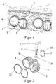
- Figure 1 shows a perspective view of a section of an inventive Air intake duct system 1.
- One intake manifold housing has 2 intake ducts 3, which are each divided into individual channels 4 and 5.
- In the single channel 5 is a shaft 6 with a swirl flap 7, the shafts 6 by a Drive device 8 are operated.
- the shaft 6 is in one piece Housing part 9 mounted. Included in this particular embodiment the housing part 9 both the single channel 4 and the single channel 5 in the Wave 6 is enough.
- the swirl flap 7 is arranged on the shaft 6 by means of clip elements 10. On the surface of the housing part facing away from the swirl flap 7 9, rib elements 11 are arranged in the present exemplary embodiment, that deform when inserting the housing part 9 into the intake manifold housing 2 can and create a clamp connection accordingly.
- a circumferential Sealing element 12 is provided, but also directly in a known manner the housing part 9 can be injection molded.
- a lever 13 is provided on the shaft 6, the when inserting the housing part 9 into the intake manifold housing 2 in the drive device 8 engages.
- the shaft 6 is sealed with respect to that Housing part 9 by a lip seal 14 or the like. It should be clear be that of course a housing part can be provided that only includes the individual channel 5, while the individual channel 4 already in the intake manifold housing 2 is formed.
- FIG. 3 shows a further possible embodiment of the swirl flap 7 the swirl flap 7 is inserted through the shaft 6 and fastened by means of clip elements 10.
- Stop elements 15 and 16 act in the radial and axial directions with respect to the shaft axis of the shaft 6 on the swirl flap 7. Particularly clear the swirl flap 7 is fastened by means of the clip elements 10 in FIG. 4 see.
- the stop elements 15 ensure the radial end stop Direction of the shaft axis of shaft 6.
- FIGS 6 Another possibility of attaching the swirl flap 7 is shown in FIGS 6 shown.
- the swirl flap is between shaft sections 17 and 18 clamped and by the stops 16 in the axial direction fixed.
Landscapes
- Engineering & Computer Science (AREA)
- Chemical & Material Sciences (AREA)
- Combustion & Propulsion (AREA)
- Mechanical Engineering (AREA)
- General Engineering & Computer Science (AREA)
- Characterised By The Charging Evacuation (AREA)
- Control Of Throttle Valves Provided In The Intake System Or In The Exhaust System (AREA)
Abstract
Description
- Figur 1
- einen Ausschnitt des erfindungsgemäßen Luftansaugkanalsystems in einer perspektivischen Ansicht,
- Figur 2
- eine Ausführungsform des Gehäuseteils mit Drallklappe in Explosionsansicht,
- Figur 3
- eine Vorderansicht einer Ausführungsform einer Drallklappe,
- Figur 4
- eine Schnittansicht gemäß IV-IV aus Figur 3,
- Figur 5
- eine Vorderansicht einer weiteren Ausführungsform einer Drallklappe, und
- Figur 6
- eine Seitenansicht der Drallklappe aus Figur 5.
Claims (11)
- Luftansaugkanalsystem für eine Brennkraftmaschine mit einem Saugrohrgehäuse mit zu den Zylindern führenden Ansaugkanälen, die wiederum in zwei Einzelkanäle unterteilt sind, von denen jeweils ein Einzelkanal eine Welle mit einer Drallklappe aufweist, die durch eine Antriebsvorrichtung drehbar ist, dadurch gekennzeichnet, daß die Welle (6) mit der Drallklappe (7) in einem Gehäuseteil (9) gelagert ist, wobei das Gehäuseteil (9) in dem Saugrohrgehäuse (2) einsetzbar ist, derart, daß die Welle (6) in die Antriebsvorrichtung eingreift.
- Luftansaugkanalsystem nach Anspruch 1, dadurch gekennzeichnet, daß das Gehäuseteil (9) durch eine Klemmverbindung im Saugrohrgehäuse (2) fixiert ist.
- Luftansaugkanalsystem nach Anspruch 2, dadurch gekennzeichnet, daß das Gehäuseteil (9) auf der von der Drallklappe (7) abgewandten Oberfläche zumindest teilweise eine derartige Rauhigkeit aufweist, daß die Klemmverbindung aufgrund der Oberflächenbeschaffenheit herstellbar ist.
- Luftansaugkanalsystem nach Anspruch 2, dadurch gekennzeichnet, daß das Gehäuseteil (9) auf der von der Drallklappe (7) abgewandten Oberfläche Rippenelemente (11) aufweist.
- Luftansaugkanalsystem nach einem der vorhergehenden Ansprüche, dadurch gekennzeichnet, daß das Gehäuseteil (9) aus einem Stück gefertigt ist.
- Luftansaugkanalsystem nach einem der vorhergehenden Ansprüche, dadurch gekennzeichnet, daß eine zu den Zylindern der Brennkraftmaschine gerichtete Seite des Gehäuseteils (9) ein umlaufendes Dichtungselement (12) aufweist.
- Luftansaugkanalsystem nach Anspruch 6, dadurch gekennzeichnet, daß das umlaufende Dichtungselement angespritzt ist.
- Luftansaugkanalsystem nach einem der vorhergehenden Ansprüche, dadurch gekennzeichnet, daß die Drallklappe (7) mittels Clipselementen (10) mit der Welle (6) verbunden ist.
- Luftansaugkanalsystem nach einem der Ansprüche 1-7, dadurch gekennzeichnet, daß zwei Wellenabschnitte (17,18) vorgesehen sind, zwischen denen die Drallklappe (7) eingeklemmt ist.
- Luftansaugkanalsystem nach einem der Ansprüche 8-9, dadurch gekennzeichnet, daß Anschlagelemente (15, 16) vorgesehen sind, die in axialer und/oder radialer Richtung in Bezug auf die Wellenachse auf die Drallklappe (7) wirken.
- Luftansaugkanalsystem nach einem der vorhergehenden Ansprüche, dadurch gekennzeichnet, daß das Gehäuseteil (9) beide Einzelkanäle (4, 5) umfaßt.
Applications Claiming Priority (2)
| Application Number | Priority Date | Filing Date | Title |
|---|---|---|---|
| DE10112070 | 2001-03-12 | ||
| DE10112070A DE10112070A1 (de) | 2001-03-12 | 2001-03-12 | Luftansaugkanalsystem für eine Brennkraftmaschine |
Publications (2)
| Publication Number | Publication Date |
|---|---|
| EP1241344A2 true EP1241344A2 (de) | 2002-09-18 |
| EP1241344A3 EP1241344A3 (de) | 2006-05-10 |
Family
ID=7677298
Family Applications (1)
| Application Number | Title | Priority Date | Filing Date |
|---|---|---|---|
| EP02001834A Withdrawn EP1241344A3 (de) | 2001-03-12 | 2002-01-26 | Luftansaugkanalsystem für eine Brennkraftmaschine |
Country Status (2)
| Country | Link |
|---|---|
| EP (1) | EP1241344A3 (de) |
| DE (1) | DE10112070A1 (de) |
Cited By (3)
| Publication number | Priority date | Publication date | Assignee | Title |
|---|---|---|---|---|
| DE10310212A1 (de) * | 2003-03-08 | 2004-09-16 | Mahle Filtersysteme Gmbh | Klappenanordnung |
| WO2016110524A1 (de) * | 2015-01-07 | 2016-07-14 | Volkswagen Aktiengesellschaft | Motoranordnung mit einem zylinderkopf und einem stromaufwärts des zylinderkopfes angeordneten flansch |
| WO2025252464A1 (de) * | 2024-06-04 | 2025-12-11 | Vat Holding Ag | Ventil |
Families Citing this family (6)
| Publication number | Priority date | Publication date | Assignee | Title |
|---|---|---|---|---|
| DE10119280A1 (de) * | 2001-04-20 | 2002-11-07 | Mann & Hummel Filter | Ansaugvorrichtung |
| DE102004004000B4 (de) * | 2004-01-26 | 2013-08-29 | Volkswagen Ag | Brennkraftmaschine mit einem Saugrohr |
| DE112008000477A5 (de) * | 2007-03-01 | 2010-01-28 | Avl List Gmbh | Einlassrohranordnung für eine Brennkraftmaschine |
| AT502970B1 (de) * | 2007-03-01 | 2008-05-15 | Avl List Gmbh | Einlassrohranordnung für eine brennkraftmaschine |
| FR2983250B1 (fr) | 2011-11-28 | 2013-12-20 | Valeo Sys Controle Moteur Sas | Systeme d'admission de gaz pour un moteur de vehicule |
| JP6821488B2 (ja) * | 2017-03-27 | 2021-01-27 | トヨタ紡織株式会社 | シール部材及びインテークマニホールド |
Family Cites Families (4)
| Publication number | Priority date | Publication date | Assignee | Title |
|---|---|---|---|---|
| US4213595A (en) * | 1978-05-04 | 1980-07-22 | Avm Corporation | Butterfly valve |
| JP3059093B2 (ja) * | 1994-12-26 | 2000-07-04 | 日本碍子株式会社 | 高温流体用バタフライ弁 |
| DE19800207A1 (de) * | 1997-03-20 | 1998-09-24 | Mann & Hummel Filter | Saugmodul |
| BR0013488A (pt) * | 1999-08-24 | 2002-05-07 | Siemens Ag | Equipamento de aspiração para um motor de combustão interna |
-
2001
- 2001-03-12 DE DE10112070A patent/DE10112070A1/de not_active Withdrawn
-
2002
- 2002-01-26 EP EP02001834A patent/EP1241344A3/de not_active Withdrawn
Cited By (3)
| Publication number | Priority date | Publication date | Assignee | Title |
|---|---|---|---|---|
| DE10310212A1 (de) * | 2003-03-08 | 2004-09-16 | Mahle Filtersysteme Gmbh | Klappenanordnung |
| WO2016110524A1 (de) * | 2015-01-07 | 2016-07-14 | Volkswagen Aktiengesellschaft | Motoranordnung mit einem zylinderkopf und einem stromaufwärts des zylinderkopfes angeordneten flansch |
| WO2025252464A1 (de) * | 2024-06-04 | 2025-12-11 | Vat Holding Ag | Ventil |
Also Published As
| Publication number | Publication date |
|---|---|
| DE10112070A1 (de) | 2002-09-19 |
| EP1241344A3 (de) | 2006-05-10 |
Similar Documents
| Publication | Publication Date | Title |
|---|---|---|
| EP0726388A1 (de) | Ansaugsystem | |
| EP1157200B1 (de) | Luftansaugsystem für eine brennkraftmaschine | |
| DE102010019427A1 (de) | Ansaugkrümmersystem für Verbrennungsmotor | |
| DE19614474B4 (de) | Luftansaugkanalsystem für Brennkraftmaschinen | |
| EP1200718B1 (de) | Saugrohranlage | |
| EP0494344A1 (de) | Dichtsystem für Drosselklappenkonstruktion mit Vollwelle | |
| EP1241344A2 (de) | Luftansaugkanalsystem für eine Brennkraftmaschine | |
| EP1260697B1 (de) | Aufgeladene Brennkraftmaschine | |
| EP1085197B1 (de) | Luftansaugkanalsystem für Brennkraftmaschinen | |
| DE3711859A1 (de) | Mehrzylindrige hubkolben-brennkraftmaschine | |
| DE60016895T2 (de) | Vorrichtung für brennkraftmaschinen | |
| EP0098543B1 (de) | Register-Luftansauganlage für Brennkraftmaschinen, insbesondere Mehrzylinder-Einspritz-Brennkraftmaschinen | |
| DE19756332B4 (de) | Luftansaugkanalsystem für eine Brennkraftmaschine | |
| EP1131546B1 (de) | Schaltwalze | |
| EP0508188B1 (de) | Ansaugsystem für eine selbstzündende Brennkraftmaschine | |
| DE102006037761A1 (de) | Befestigungsanordnung für einen Ladeluftkühler und einen Wasserkühler | |
| WO2005017341A1 (de) | Saugmodul für eine brennkraftmaschine | |
| EP1342001B1 (de) | Anordnung zum lösbaren befestigen einer ansaugvorrichtung am zylinderkopf | |
| DE19651642A1 (de) | Lufteinlaßkanalsystem für Brennkraftmaschinen | |
| DE10346005B4 (de) | Luftansaugmodul für eine Brennkraftmaschine mit Impulsaufladung | |
| DE10348361B4 (de) | Saugrohr für eine Brennkraftmaschine | |
| DE102004002641A1 (de) | Modulare Ansaugvorrichtung | |
| DE102008049019A1 (de) | Saugrohr einer Brennkraftmaschine | |
| EP1124043B1 (de) | Luftansaugkanalsystem für eine Brennkraftmaschine | |
| DE102004004000B4 (de) | Brennkraftmaschine mit einem Saugrohr |
Legal Events
| Date | Code | Title | Description |
|---|---|---|---|
| PUAI | Public reference made under article 153(3) epc to a published international application that has entered the european phase |
Free format text: ORIGINAL CODE: 0009012 |
|
| 17P | Request for examination filed |
Effective date: 20020126 |
|
| AK | Designated contracting states |
Kind code of ref document: A2 Designated state(s): AT BE CH CY DE DK ES FI FR GB GR IE IT LI LU MC NL PT SE TR |
|
| AX | Request for extension of the european patent |
Free format text: AL;LT;LV;MK;RO;SI |
|
| PUAL | Search report despatched |
Free format text: ORIGINAL CODE: 0009013 |
|
| STAA | Information on the status of an ep patent application or granted ep patent |
Free format text: STATUS: THE APPLICATION HAS BEEN WITHDRAWN |
|
| AK | Designated contracting states |
Kind code of ref document: A3 Designated state(s): AT BE CH CY DE DK ES FI FR GB GR IE IT LI LU MC NL PT SE TR |
|
| AX | Request for extension of the european patent |
Extension state: AL LT LV MK RO SI |
|
| 18W | Application withdrawn |
Effective date: 20060410 |