EP1241059A2 - Inflatable curtain assembly - Google Patents
Inflatable curtain assembly Download PDFInfo
- Publication number
- EP1241059A2 EP1241059A2 EP02005784A EP02005784A EP1241059A2 EP 1241059 A2 EP1241059 A2 EP 1241059A2 EP 02005784 A EP02005784 A EP 02005784A EP 02005784 A EP02005784 A EP 02005784A EP 1241059 A2 EP1241059 A2 EP 1241059A2
- Authority
- EP
- European Patent Office
- Prior art keywords
- vehicle
- support device
- inflatable
- grab handle
- fill tube
- Prior art date
- Legal status (The legal status is an assumption and is not a legal conclusion. Google has not performed a legal analysis and makes no representation as to the accuracy of the status listed.)
- Withdrawn
Links
- 239000012530 fluid Substances 0.000 claims description 32
- 230000003014 reinforcing effect Effects 0.000 description 6
- 239000000463 material Substances 0.000 description 5
- 238000010276 construction Methods 0.000 description 2
- 239000002184 metal Substances 0.000 description 2
- 238000012986 modification Methods 0.000 description 2
- 230000004048 modification Effects 0.000 description 2
- 239000000853 adhesive Substances 0.000 description 1
- 230000001070 adhesive effect Effects 0.000 description 1
- 238000002485 combustion reaction Methods 0.000 description 1
- 238000010438 heat treatment Methods 0.000 description 1
- 238000009434 installation Methods 0.000 description 1
Images

Classifications
-
- B—PERFORMING OPERATIONS; TRANSPORTING
- B60—VEHICLES IN GENERAL
- B60R—VEHICLES, VEHICLE FITTINGS, OR VEHICLE PARTS, NOT OTHERWISE PROVIDED FOR
- B60R21/00—Arrangements or fittings on vehicles for protecting or preventing injuries to occupants or pedestrians in case of accidents or other traffic risks
- B60R21/02—Occupant safety arrangements or fittings, e.g. crash pads
- B60R21/16—Inflatable occupant restraints or confinements designed to inflate upon impact or impending impact, e.g. air bags
- B60R21/23—Inflatable members
- B60R21/231—Inflatable members characterised by their shape, construction or spatial configuration
- B60R21/232—Curtain-type airbags deploying mainly in a vertical direction from their top edge
Definitions
- the present invention relates to an inflatable curtain that is inflatable between a side structure of a vehicle and a vehicle occupant.
- the present invention relates to an assembly for connecting an inflatable curtain to a vehicle.
- an inflatable curtain to help protect a vehicle occupant in the event of a vehicle collision and/or a vehicle rollover.
- inflatable curtains are inflatable from the roof of the vehicle between a vehicle occupant and a side structure of the vehicle.
- the inflatable curtain is inflated from a deflated condition by inflation fluid directed from an inflator to the inflatable curtain through a fill tube.
- Known inflatable curtains are stored in a folded, deflated condition in a housing.
- a support device such as a clamp or bracket is used to connect the fill tube and the inflatable curtain to the vehicle via fasteners. It is also known to provide a grab handle in a vehicle. Known grab handles are typically connected to the vehicle via fasteners.
- the present invention relates to an apparatus for helping to protect an occupant of a vehicle that has a side structure and a roof.
- the apparatus includes an inflatable vehicle occupant protection device that is inflatable away from the vehicle roof into a position between the side structure of the vehicle and the vehicle occupant.
- a fill tube has a portion located in the inflatable vehicle occupant protection device.
- the apparatus also includes at least one support device that has a portion that clamps around a portion of the fill tube.
- the apparatus further includes a grab handle that has at least one portion adapted to interconnect with the support device.
- a fastener is extendable through the support device to connect the grab handle, support device, fill tube and inflatable vehicle occupant protection device to the vehicle.
- an apparatus 10 helps to protect an occupant of a vehicle 12.
- the apparatus 10 includes an inflatable vehicle occupant protection device in the form of an inflatable curtain 14 that is mounted adjacent the side structure 16 of the vehicle 12 and a roof 18 of the vehicle.
- the side structure 16 of the vehicle 12 includes side windows 20.
- An inflator 24 is connected in fluid communication with the inflatable curtain 14 through a fill tube 22.
- the fill tube 22 has a first end portion 30 for receiving fluid from the inflator 24.
- the fill tube 22 has a second end portion 32 disposed in the inflatable curtain 14.
- the second end portion 32 of the fill tube 22 has a plurality of openings (not shown) that provide fluid communication between the fill tube 22 and the inflatable curtain 14.
- the inflator 24 contains a stored quantity of pressurized inflation fluid (not shown) in the form of a gas to inflate the inflatable curtain 14.
- the inflator 24 alternatively could contain a combination of pressurized inflation fluid and ignitable material for heating the inflation fluid, or could be a pyrotechnic inflator that uses the combustion of gas-generating material to generate inflation fluid.
- the inflator 24 could be of any suitable type or construction for supplying a medium for inflating the inflatable curtain 14.
- the apparatus 10 includes a housing 26 that stores the inflatable curtain 14 in a deflated condition (not shown).
- the fill tube 22, the deflated inflatable curtain 14, and housing 26 have an elongated configuration and extend along the vehicle roof 18 and along the side structure 16 of the vehicle 12 above the side windows 20.
- the vehicle 12 includes a sensor mechanism 36 (shown schematically in Fig. 1) for sensing a side impact to the vehicle 12 and/or a rollover of the vehicle 12.
- the sensor mechanism 36 causes an electrical signal to be sent over lead wires 34 to the inflator 24.
- the electrical signal causes the inflator 24 to be actuated in a known manner.
- the inflator 24 discharges fluid under pressure into the fill tube 22.
- the fill tube 22 directs the fluid into the inflatable curtain 14.
- the inflatable curtain 14 inflates under the pressure of the inflation fluid into the position of Fig. 1, between the side structure 16 of the vehicle 12 and any occupants of the vehicle 12.
- the inflatable curtain 14 when inflated, extends along the side structure 16 of the vehicle 12 and is positioned between the side structure and any occupant of the vehicle.
- an upper edge 200 of the curtain is positioned adjacent the intersection of the roof 18 and the side structure 16 of the vehicle 12.
- a front edge 202 of the inflatable curtain 14 is positioned adjacent an A pillar 210 of the vehicle 12.
- a rear edge 204 of the inflatable curtain 14 is positioned adjacent a C pillar 212 of the vehicle 12.
- the inflatable curtain 14 extends between the A pillar 210 and the C pillar 212 of the vehicle 12 and overlies at least a portion of the A pillar, C pillar, and a B pillar 214 of the vehicle.
- the inflatable curtain may have alternative configurations.
- the inflatable curtain 14 extends between the A pillar 210 and the C pillar 212 of the vehicle 12.
- the inflatable curtain 14 could, however, extend between the A pillar 210 and the B pillar 214 only or between the B pillar and the C pillar 212 only.
- the inflatable curtain 14 could, when inflated, extend between the A pillar 210 and a D pillar (not shown) of the vehicle 12.
- the inflatable curtain 14 when inflated, helps to protect a vehicle occupant in the event of a vehicle rollover or a side impact to the vehicle 12.
- a plurality of support devices 40 connect the inflatable curtain 14 and fill tube 22 to the side structure 16 of the vehicle 12.
- the support devices 40 are operable from an open position illustrated in Figs. 2a and 2b to a closed position illustrated in Fig. 3 to connect the support device to the fill tube 22.
- each support device 40 consists of a clamping portion 42 and a fastening portion 44.
- the support device 40 is constructed of a single piece of high-strength plastic material that is molded to form the clamping portion 42 and fastening portion 44.
- the support device 40 could be formed of a single piece of metal that is cut in a predetermined pattern and folded or bent to form the support device.
- the clamping portion 42 includes an arc-shaped end portion 50 and first and second side walls 52 and 54 that extend from opposite ends of the end portion.
- a flat bottom portion 56 of the clamping portion 42 extends generally perpendicularly from the first side wall 52 to adjacent the second side wall 54 when the support device 40 is in the closed position of Fig. 3.
- the end portion 50, first and second side walls 52 and 54, and bottom portion 56 form an inner clamping surface 60 (Figs. 2a, 2b and 3) of the clamping portion 42.
- a first clamp flange 70 extends from the second side wall 54 in a direction perpendicular to the bottom portion 56.
- a second clamp flange 74 extends from an end of the bottom portion 56 adjacent the second side wall 54 of the end portion 50 in a direction perpendicular to the bottom portion.
- the first and second clamp flanges 70 and 74 are positioned in an adjacent and overlying relationship when the support device 40 is in the closed position of Fig. 3.
- the fastening portion 44 includes a rectangular bottom wall 80 formed by the overlying first and second clamp flanges 70 and 74.
- First and second opposite side walls 82 and 84 and first and second opposing end walls 86 and 88 extend perpendicularly from the bottom wall 80 to form a chamber 90 of the support device 40.
- the first side wall 82 is defined by the bottom portion 56 of the clamping portion 50.
- the second side wall 84 (Fig. 2a) extends perpendicularly from the second clamp flange 74 in a direction parallel to the first side wall 82.
- a pair of spaced first reinforcing walls 92 extend from the fist side wall 82 to the second side wall 84.
- Second reinforcing walls 94 extend perpendicularly from the first reinforcing walls 92 to the end walls 86 and 88, respectively.
- the first reinforcing walls 92 and the first and second side walls 82 and 84 help define a fastener receiving chamber 100 in the chamber 90.
- a terminal end portion of the first clamp flange 70 forms a latch portion 102 of the support device 40.
- the latch portion 102 includes a base member 104 that extends generally perpendicularly from the first clamp flange 70 and a latch member 106 that extends perpendicularly from the base member 104.
- Housing support flanges 108 extend perpendicularly from longitudinal edges of the second side wall 84 in a direction away from the chamber 90.
- An elongated fastener opening 120 extends through the bottom wall 80 of the chamber 90, i.e., through the first and second clamp flanges 70 and 74.
- the fastener opening 120 is preferably centered between the first and second side walls 82 and 84 and the first and second end walls 86 and 88.
- the inflatable curtain 14 includes cutout portions 130 spaced along its length. Each cutout portion 130 extends entirely through the inflatable curtain 14. The perimeter of each cutout portion 130 is sealed by means (not shown), such as stitching or an adhesive to help block leakage of inflation fluid through the cutout portions when the inflatable curtain 14 is inflated.
- the fill tube 22 (Figs. 4 and 5) is generally cylindrical in shape and includes a series of clamp sections 140 spaced along its length.
- the cylindrical fill tube 22 is flattened on one side along the extent of each clamping section 140.
- the fill tube 22 has an arc-shaped portion 142 and a flat bottom portion 144 along the length of each clamp section 140.
- the spacing of the cutout portions 130 (Fig. 1) on the inflatable curtain 14 is equidistant with the spacing of the clamp sections 140 on the fill tube 22. The cutout portions 130 are thus positioned adjacent the clamp sections 140 when the fill tube 22 is fully inserted into the inflatable curtain 14.
- the apparatus 10 also includes grab handles 150 that are spaced apart along the length of the vehicle 12.
- grab handles 150 there are two such grab handles 150.
- One of the grab handles 150 is positioned above the forward vehicle side window 20 of the vehicle 12, and the other grab handle is positioned above the rearward side window of the vehicle.
- Each grab handle 150 (Fig. 6) has a first end 152 and an opposite second end 154.
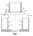
- An anchor portion 156 (Figs. 6 and 7) extends from each of the first and second ends 152 and 154 of the grab handle 150.
- Each of the anchor portions 156 include a latch portions 160 positioned near the end of the anchor portion on opposite sides of the anchor portion.
- the latch portions 160 each include a guide surface 162 and a latch surface 164.
- the fill tube 22 is inserted into the inflatable curtain 14. As illustrated in Fig. 4, the first and second clamp flanges 70 and 74 of the support device 40 are spaced apart, thus placing the support device in the open position. The clamping portion 42 of the support device 40 receives the fill tube 22.
- the clamp section 140 of the fill tube 22 is positioned within the clamping portion 42. Once the fill tube 22 is inserted into the clamping portion 42, as indicated by the dot-dash line in Fig. 4, the first and second clamp flanges 70 and 74 are moved together, thus placing the support device in the closed position. This is illustrated in Fig. 5.
- the arc-shaped end portion 50 (Fig. 5) of the clamping portion 42 is positioned adjacent the arc-shaped portion 142 of the clamp section 140.
- the bottom portion 56 of the clamping portion 42 is positioned adjacent the bottom portion 144 of the clamp section 140.
- first and second clamp flanges 70 and 74 When the first and second clamp flanges 70 and 74 are moved together, they become positioned adjacent one another. As the first and second clamp flanges 70 and 74 of the fastening portion 44 are drawn together, the latch portion 102 receives a longitudinal edge 110 of the second clamp flange 74. The latch member 106 engages the longitudinal edge 110 of the second clamp flange 74 to lock the support device 40 in the closed position. This causes a clamping force to be applied to the fill tube 22 by the inner clamping surface 60 of the clamping portion 42. The support device 40 is thus secured to the fill tube 22. The cutout portions 130 leave the support devices 40, particularly the chamber 90 and the fastener receiving chamber 100, unobstructed by the inflatable curtain 14.
- the housing 26 is positioned around the inflatable curtain 14, fill tube 22, and support device 40.
- the housing support flanges 108 of each support device 40 engage the housing 26 and help to maintain its position relative to the support device 40.
- the housing 26 is cut away at locations 166 along its length. The spacing of the cut away locations 166 of the housing 26 is such that the fastener receiving chambers 100 of the support devices 40 are exposed at spaced locations along the length of the housing.
- a headliner 170 of the vehicle 12 overlies the housing 26 and the support device 40, as well as the inflatable curtain 14 and the fill tube 22.
- the first and second ends 152 and 154 of the grab handles 150 are associated with respective support devices 40.
- the anchor portions 156 of the grab handle 150 are inserted through respective apertures 172 in the headliner 170 and extend into the fastener receiving chamber 100 of the respective support devices 40.
- the rectangular dimensions of the anchor portions 156 form a close fit with the rectangular dimensions of the fastener receiving chamber 100.
- the guide surfaces 162 of the latch portions 160 engage the first reinforcing side walls 92.
- this may cause the anchor portions and/or the fastener receiving chambers 100 to deflect as the anchor portions enter the respective fastener receiving chambers.
- the latch portions 160 of each anchor portion reach respective dentations 174 that protrude from the first reinforcing walls 92.
- the resiliency of the material used to construct the anchor portions 156 and the support device 40 causes the latch portions 160 to "snap" around the dentations 174.
- the latch surfaces 164 of the latch portions 160 engage the dentations 174, which helps to retain the anchor portions 156 in the fastener receiving chamber 100.
- the anchor portions 156 thus connect the grab handle 150 to the support device 40.
- the apparatus 10 includes four cutout portions 130, four clamping portions 140, and four support devices 40.
- each support device 40 is fixedly connected to the side structure 16 of the vehicle 12 by a threaded fastener 180, such as a screw. As illustrated in Figs. 6 and 8, the threaded fastener 180 is inserted into a chamber 186 in the grab handle 150, into the fastener receiving chamber 100, and through the fastener opening 120 in the bottom wall 80.
- the fastener opening 120 is aligned with a location 182, such as an opening, in the side structure 16 of the vehicle 12 to receive the threaded fastener 180.
- the location 182 may include a threaded stud 190 (Fig. 8) for receiving the fastener 180.
- the threaded fastener 180 connects the support device 40, and thus the fill tube 22, inflatable curtain 14 and grab handles 150, to the side structure 16 of the vehicle 12.
- portions 184 of the grab handle 150 overlie the headliner 170.
- the portions 184 impinge the headliner 170 between the grab handle 150 and the support device 40 and between the grab handle and the housing 26 to help connect the headliner to the vehicle 12.
- the invention relates to an apparatus for helping to protect an occupant of a vehicle having a side structure and a roof, said apparatus comprising:
- An apparatus for helping to protect an occupant of a vehicle having a side structure and a roof comprising:
- said at least one portion of said grab handle comprises an anchor portion insertable into a fastener receiving portion of said at least one support device, said anchor portion including at least one latch portion that engages said at least one support device to connect said grab handle to said at least one support device.
- Apparatus wherein said at least one latch portion of said anchor portion extends around a dentation extending from a surface of said fastener receiving portion, said latch portion including a surface that engages said dentation to connect said grab handle to said at least one support device.
- Apparatus further including a headliner overlying the roof of the vehicle between the roof and an occupant of the vehicle, said inflatable vehicle occupant protection device, said fill tube, and said at least one support device being adapted to be positioned between the headliner and the roof of the vehicle, said anchor portions being extendable through the headliner into said fastener receiving portion of said at least one support device.
- said grab handle has a first end and an opposite second end, said anchor portions extending from said first and second ends of said grab handle in a first direction, parallel to each other.
- Apparatus wherein said inflatable vehicle occupant protection device and said fill tube, when connected to the vehicle, extend along the intersection of the side structure of the vehicle and the vehicle roof.
- Apparatus wherein said at least one support device, said grab handle, and said at least one fastener cooperate to help support the headliner in the vehicle.
- Apparatus wherein said at least one fastener extends through said grab handle to help connect said grab handle to the vehicle.
- Apparatus further comprising an inflation fluid source that provides inflation fluid for inflating said inflatable vehicle occupant protection device.
- said inflatable vehicle occupant protection device is an inflatable curtain having a stored position extending along the side structure adjacent a roof of the vehicle, said inflatable curtain being inflated away from the vehicle roof into said position between the side structure of the vehicle and a vehicle occupant.
- said inflation fluid source is in fluid communication with said fill tube, said inflation fluid source, when actuated, providing inflation fluid to said fill tube, said fill tube directing said inflation fluid into said inflatable curtain to inflate said inflatable curtain.
- Apparatus wherein said inflatable curtain, when inflated, extends along the side structure of the vehicle between an A pillar and a C pillar of the vehicle.
- Apparatus wherein said inflatable curtain, when inflated, overlies at least a portion of an A pillar, a B pillar and a C pillar of the vehicle.
- Apparatus further comprising a sensor for sensing a vehicle condition for which deployment of said inflatable curtain is desired, said sensor actuating said inflation fluid source to provide inflation fluid to inflate said inflatable curtain.
- said inflation fluid source comprises an inflator which is actuatable to inflate said inflatable curtain.
Landscapes
- Engineering & Computer Science (AREA)
- Mechanical Engineering (AREA)
- Air Bags (AREA)
Abstract
Description
- The present invention relates to an inflatable curtain that is inflatable between a side structure of a vehicle and a vehicle occupant. In particular, the present invention relates to an assembly for connecting an inflatable curtain to a vehicle.
- It is known to inflate an inflatable curtain to help protect a vehicle occupant in the event of a vehicle collision and/or a vehicle rollover. Such inflatable curtains are inflatable from the roof of the vehicle between a vehicle occupant and a side structure of the vehicle. The inflatable curtain is inflated from a deflated condition by inflation fluid directed from an inflator to the inflatable curtain through a fill tube.
- Known inflatable curtains are stored in a folded, deflated condition in a housing. A support device such as a clamp or bracket is used to connect the fill tube and the inflatable curtain to the vehicle via fasteners. It is also known to provide a grab handle in a vehicle. Known grab handles are typically connected to the vehicle via fasteners.
- The present invention relates to an apparatus for helping to protect an occupant of a vehicle that has a side structure and a roof. The apparatus includes an inflatable vehicle occupant protection device that is inflatable away from the vehicle roof into a position between the side structure of the vehicle and the vehicle occupant. A fill tube has a portion located in the inflatable vehicle occupant protection device. The apparatus also includes at least one support device that has a portion that clamps around a portion of the fill tube. The apparatus further includes a grab handle that has at least one portion adapted to interconnect with the support device. A fastener is extendable through the support device to connect the grab handle, support device, fill tube and inflatable vehicle occupant protection device to the vehicle.
- The foregoing and other features of the present invention will become apparent to one skilled in the art to which the present invention relates upon consideration of the following description of the invention with reference to the accompanying drawings, in which:
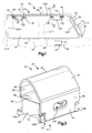
- Fig. 1 is a schematic representation of a side elevation of an apparatus for helping to protect a vehicle occupant, according to the present invention;
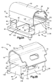
- Figs. 2a and 2b are perspective views of a support device which forms a portion of the apparatus of Fig. 1, depicting the support device in an open condition;
- Fig. 3 is a perspective view of the support device of Figs. 2a and 2b depicting the support device in a closed condition;
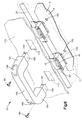
- Fig. 4 is a sectional view of a portion of the apparatus of Fig. 1 depicting the assembly of certain parts of the apparatus;
- Fig. 5 is a sectional view of a portion of the apparatus of Fig. 1 showing certain parts assembled;
- Fig. 6 is an perspective view of the apparatus of Fig. 1 depicting the assembly of the apparatus of Fig. 1;
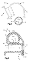
- Fig. 7 is a sectional view of a portion of the apparatus taken generally along line 7-7 in Fig. 6, with certain parts omitted; and
- Fig. 8 is a sectional view of the apparatus taken generally along line 8-8 in Fig. 1.
-
- As representative of the present invention, an
apparatus 10 helps to protect an occupant of avehicle 12. As shown in Fig. 1, theapparatus 10 includes an inflatable vehicle occupant protection device in the form of aninflatable curtain 14 that is mounted adjacent theside structure 16 of thevehicle 12 and aroof 18 of the vehicle. Theside structure 16 of thevehicle 12 includesside windows 20. Aninflator 24 is connected in fluid communication with theinflatable curtain 14 through afill tube 22. - The
fill tube 22 has afirst end portion 30 for receiving fluid from theinflator 24. Thefill tube 22 has asecond end portion 32 disposed in theinflatable curtain 14. Thesecond end portion 32 of thefill tube 22 has a plurality of openings (not shown) that provide fluid communication between thefill tube 22 and theinflatable curtain 14. - The
inflator 24 contains a stored quantity of pressurized inflation fluid (not shown) in the form of a gas to inflate theinflatable curtain 14. Theinflator 24 alternatively could contain a combination of pressurized inflation fluid and ignitable material for heating the inflation fluid, or could be a pyrotechnic inflator that uses the combustion of gas-generating material to generate inflation fluid. As a further alternative, theinflator 24 could be of any suitable type or construction for supplying a medium for inflating theinflatable curtain 14. - The
apparatus 10 includes ahousing 26 that stores theinflatable curtain 14 in a deflated condition (not shown). Thefill tube 22, the deflatedinflatable curtain 14, andhousing 26 have an elongated configuration and extend along thevehicle roof 18 and along theside structure 16 of thevehicle 12 above theside windows 20. - The
vehicle 12 includes a sensor mechanism 36 (shown schematically in Fig. 1) for sensing a side impact to thevehicle 12 and/or a rollover of thevehicle 12. In the event of a side impact to thevehicle 12 of a magnitude greater than a predetermined threshold value, thesensor mechanism 36 causes an electrical signal to be sent overlead wires 34 to theinflator 24. The electrical signal causes theinflator 24 to be actuated in a known manner. Theinflator 24 discharges fluid under pressure into thefill tube 22. Thefill tube 22 directs the fluid into theinflatable curtain 14. Theinflatable curtain 14 inflates under the pressure of the inflation fluid into the position of Fig. 1, between theside structure 16 of thevehicle 12 and any occupants of thevehicle 12. - The
inflatable curtain 14, when inflated, extends along theside structure 16 of thevehicle 12 and is positioned between the side structure and any occupant of the vehicle. When theinflatable curtain 14 is in the inflated condition, anupper edge 200 of the curtain is positioned adjacent the intersection of theroof 18 and theside structure 16 of thevehicle 12. Afront edge 202 of theinflatable curtain 14 is positioned adjacent anA pillar 210 of thevehicle 12. Arear edge 204 of theinflatable curtain 14 is positioned adjacent aC pillar 212 of thevehicle 12. Theinflatable curtain 14 extends between theA pillar 210 and theC pillar 212 of thevehicle 12 and overlies at least a portion of the A pillar, C pillar, and aB pillar 214 of the vehicle. - It will be recognized by those skilled in the art that the inflatable curtain may have alternative configurations. For example, in the illustrated embodiment, the
inflatable curtain 14 extends between theA pillar 210 and theC pillar 212 of thevehicle 12. Theinflatable curtain 14 could, however, extend between theA pillar 210 and theB pillar 214 only or between the B pillar and theC pillar 212 only. Also, theinflatable curtain 14 could, when inflated, extend between theA pillar 210 and a D pillar (not shown) of thevehicle 12. - The
inflatable curtain 14, when inflated, helps to protect a vehicle occupant in the event of a vehicle rollover or a side impact to thevehicle 12. Theinflatable curtain 14, when inflated, helps to absorb the energy of impacts and helps to distribute the impact energy over a large area of the curtain. - A plurality of
support devices 40 connect theinflatable curtain 14 and filltube 22 to theside structure 16 of thevehicle 12. Thesupport devices 40 are operable from an open position illustrated in Figs. 2a and 2b to a closed position illustrated in Fig. 3 to connect the support device to thefill tube 22. As illustrated in Figs. 2a, 2b and 3, eachsupport device 40 consists of aclamping portion 42 and afastening portion 44. Preferably, thesupport device 40 is constructed of a single piece of high-strength plastic material that is molded to form the clampingportion 42 andfastening portion 44. Those skilled in the art, however, will recognize that alternative high-strength materials, such as metal, and alternative designs, such as a multi-piece construction, may also be suitable for constructing thesupport device 40. For example, thesupport device 40 could be formed of a single piece of metal that is cut in a predetermined pattern and folded or bent to form the support device. - The clamping
portion 42 includes an arc-shapedend portion 50 and first andsecond side walls flat bottom portion 56 of the clampingportion 42 extends generally perpendicularly from thefirst side wall 52 to adjacent thesecond side wall 54 when thesupport device 40 is in the closed position of Fig. 3. Theend portion 50, first andsecond side walls bottom portion 56 form an inner clamping surface 60 (Figs. 2a, 2b and 3) of the clampingportion 42. - A
first clamp flange 70 extends from thesecond side wall 54 in a direction perpendicular to thebottom portion 56. Asecond clamp flange 74 extends from an end of thebottom portion 56 adjacent thesecond side wall 54 of theend portion 50 in a direction perpendicular to the bottom portion. The first andsecond clamp flanges support device 40 is in the closed position of Fig. 3. - The
fastening portion 44 includes arectangular bottom wall 80 formed by the overlying first andsecond clamp flanges opposite side walls end walls bottom wall 80 to form achamber 90 of thesupport device 40. Thefirst side wall 82 is defined by thebottom portion 56 of the clampingportion 50. The second side wall 84 (Fig. 2a) extends perpendicularly from thesecond clamp flange 74 in a direction parallel to thefirst side wall 82. A pair of spaced first reinforcingwalls 92 extend from thefist side wall 82 to thesecond side wall 84. Second reinforcingwalls 94 extend perpendicularly from the first reinforcingwalls 92 to theend walls walls 92 and the first andsecond side walls fastener receiving chamber 100 in thechamber 90. - A terminal end portion of the
first clamp flange 70 forms alatch portion 102 of thesupport device 40. Thelatch portion 102 includes abase member 104 that extends generally perpendicularly from thefirst clamp flange 70 and alatch member 106 that extends perpendicularly from thebase member 104.Housing support flanges 108 extend perpendicularly from longitudinal edges of thesecond side wall 84 in a direction away from thechamber 90. - An
elongated fastener opening 120 extends through thebottom wall 80 of thechamber 90, i.e., through the first andsecond clamp flanges fastener opening 120 is preferably centered between the first andsecond side walls second end walls - As illustrated in Fig. 1, the
inflatable curtain 14 includescutout portions 130 spaced along its length. Eachcutout portion 130 extends entirely through theinflatable curtain 14. The perimeter of eachcutout portion 130 is sealed by means (not shown), such as stitching or an adhesive to help block leakage of inflation fluid through the cutout portions when theinflatable curtain 14 is inflated. - The fill tube 22 (Figs. 4 and 5) is generally cylindrical in shape and includes a series of
clamp sections 140 spaced along its length. Thecylindrical fill tube 22 is flattened on one side along the extent of eachclamping section 140. Thus, thefill tube 22 has an arc-shapedportion 142 and aflat bottom portion 144 along the length of eachclamp section 140. The spacing of the cutout portions 130 (Fig. 1) on theinflatable curtain 14 is equidistant with the spacing of theclamp sections 140 on thefill tube 22. Thecutout portions 130 are thus positioned adjacent theclamp sections 140 when thefill tube 22 is fully inserted into theinflatable curtain 14. - As illustrated in Fig. 1, the
apparatus 10 also includes grab handles 150 that are spaced apart along the length of thevehicle 12. In the embodiment illustrated in Fig. 1, there are two such grab handles 150. One of the grab handles 150 is positioned above the forwardvehicle side window 20 of thevehicle 12, and the other grab handle is positioned above the rearward side window of the vehicle. Each grab handle 150 (Fig. 6) has afirst end 152 and an oppositesecond end 154. An anchor portion 156 (Figs. 6 and 7) extends from each of the first and second ends 152 and 154 of thegrab handle 150. Each of theanchor portions 156 include alatch portions 160 positioned near the end of the anchor portion on opposite sides of the anchor portion. As illustrated in Fig. 7, thelatch portions 160 each include aguide surface 162 and alatch surface 164. - Assembly of the
fill tube 22, theinflatable curtain 14,support devices 40, and grab handles 150 is required prior to installation in thevehicle 12. Thefill tube 22 is inserted into theinflatable curtain 14. As illustrated in Fig. 4, the first andsecond clamp flanges support device 40 are spaced apart, thus placing the support device in the open position. The clampingportion 42 of thesupport device 40 receives thefill tube 22. - The
clamp section 140 of thefill tube 22 is positioned within the clampingportion 42. Once thefill tube 22 is inserted into the clampingportion 42, as indicated by the dot-dash line in Fig. 4, the first andsecond clamp flanges support device 40 is in the closed position, the arc-shaped end portion 50 (Fig. 5) of the clampingportion 42 is positioned adjacent the arc-shapedportion 142 of theclamp section 140. Thebottom portion 56 of the clampingportion 42 is positioned adjacent thebottom portion 144 of theclamp section 140. - When the first and
second clamp flanges second clamp flanges fastening portion 44 are drawn together, thelatch portion 102 receives alongitudinal edge 110 of thesecond clamp flange 74. Thelatch member 106 engages thelongitudinal edge 110 of thesecond clamp flange 74 to lock thesupport device 40 in the closed position. This causes a clamping force to be applied to thefill tube 22 by theinner clamping surface 60 of the clampingportion 42. Thesupport device 40 is thus secured to thefill tube 22. Thecutout portions 130 leave thesupport devices 40, particularly thechamber 90 and thefastener receiving chamber 100, unobstructed by theinflatable curtain 14. - Referring now to Fig. 8, the
housing 26 is positioned around theinflatable curtain 14, filltube 22, andsupport device 40. Thehousing support flanges 108 of eachsupport device 40 engage thehousing 26 and help to maintain its position relative to thesupport device 40. Thehousing 26 is cut away atlocations 166 along its length. The spacing of the cut awaylocations 166 of thehousing 26 is such that thefastener receiving chambers 100 of thesupport devices 40 are exposed at spaced locations along the length of the housing. Aheadliner 170 of thevehicle 12 overlies thehousing 26 and thesupport device 40, as well as theinflatable curtain 14 and thefill tube 22. - As illustrated in Fig. 6, the first and second ends 152 and 154 of the grab handles 150 are associated with
respective support devices 40. Referring now to Figs. 5-7, theanchor portions 156 of thegrab handle 150 are inserted throughrespective apertures 172 in theheadliner 170 and extend into thefastener receiving chamber 100 of therespective support devices 40. The rectangular dimensions of theanchor portions 156 form a close fit with the rectangular dimensions of thefastener receiving chamber 100. As theanchor portions 156 are inserted into thefastener receiving chamber 100, the guide surfaces 162 of thelatch portions 160 engage the first reinforcingside walls 92. Depending on the dimensional tolerances between theanchor portions 156 and thefastener receiving chambers 100, this may cause the anchor portions and/or thefastener receiving chambers 100 to deflect as the anchor portions enter the respective fastener receiving chambers. - As the
anchor portions 156 are inserted into the respectivefastener receiving chambers 100, thelatch portions 160 of each anchor portion reachrespective dentations 174 that protrude from the first reinforcingwalls 92. The resiliency of the material used to construct theanchor portions 156 and thesupport device 40 causes thelatch portions 160 to "snap" around thedentations 174. The latch surfaces 164 of thelatch portions 160 engage thedentations 174, which helps to retain theanchor portions 156 in thefastener receiving chamber 100. Theanchor portions 156 thus connect thegrab handle 150 to thesupport device 40. - As shown in Fig. 1, four
support devices 40 are used to support thefill tube 22,inflatable curtain 14 and two grab handles 150 on thevehicle 12. Thus, in the illustrated embodiment, theapparatus 10 includes fourcutout portions 130, four clampingportions 140, and foursupport devices 40. - The assembled fill tube 22 (Fig. 6),
inflatable curtain 14,support devices 40, and grabhandles 150 are located in a desired position relative to theside structure 16 of thevehicle 12. Once in the desired position, eachsupport device 40 is fixedly connected to theside structure 16 of thevehicle 12 by a threadedfastener 180, such as a screw. As illustrated in Figs. 6 and 8, the threadedfastener 180 is inserted into achamber 186 in thegrab handle 150, into thefastener receiving chamber 100, and through thefastener opening 120 in thebottom wall 80. - The
fastener opening 120 is aligned with alocation 182, such as an opening, in theside structure 16 of thevehicle 12 to receive the threadedfastener 180. Thelocation 182 may include a threaded stud 190 (Fig. 8) for receiving thefastener 180. The threadedfastener 180 connects thesupport device 40, and thus thefill tube 22,inflatable curtain 14 and grab handles 150, to theside structure 16 of thevehicle 12. When theapparatus 10 is in the position illustrated in Fig. 8,portions 184 of thegrab handle 150 overlie theheadliner 170. Theportions 184 impinge theheadliner 170 between thegrab handle 150 and thesupport device 40 and between the grab handle and thehousing 26 to help connect the headliner to thevehicle 12. - From the above description of the invention, those skilled in the art will perceive improvements, changes and modifications in the invention. Such improvements, changes and modifications within the skill of the art are intended to be covered by the appended claims.
- According to its broadest aspect, the invention relates to an apparatus for helping to protect an occupant of a vehicle having a side structure and a roof, said apparatus comprising:
- an inflatable vehicle occupant protection device inflatable away from the vehicle roof into a position between the side structure of the vehicle and the vehicle occupant;
- at least one support device ;
- a grab handle having at least one portion adapted to interconnect with said at least one support device; and
- a fastener extendable through said at least one support device to connect said grab handle, said at least one support device and said inflatable vehicle occupant protection device to the vehicle.
-
- It should be noted that objects and advantages of the invention may be attained by means of compatible combination(s) particularly pointed out in the items of the following summary of the invention.
- An apparatus for helping to protect an occupant of a vehicle having a side structure and a roof, said apparatus comprising:
- an inflatable vehicle occupant protection device inflatable away from the vehicle roof into a position between the side structure of the vehicle and the vehicle occupant;
- a fill tube having a portion located in said inflatable vehicle occupant protection device;
- at least one support device having a portion that clamps around a portion of said fill tube;
- a grab handle having at least one portion adapted to interconnect with said at least one support device; and
- a fastener extendable through said at least one support device to connect said grab handle, said at least one support device, said fill tube and said inflatable vehicle occupant protection device to the vehicle.
-
- Apparatus wherein said at least one portion of said grab handle comprises an anchor portion insertable into a fastener receiving portion of said at least one support device, said anchor portion including at least one latch portion that engages said at least one support device to connect said grab handle to said at least one support device.
- Apparatus , wherein said at least one latch portion of said anchor portion extends around a dentation extending from a surface of said fastener receiving portion, said latch portion including a surface that engages said dentation to connect said grab handle to said at least one support device.
- Apparatus , further including a headliner overlying the roof of the vehicle between the roof and an occupant of the vehicle, said inflatable vehicle occupant protection device, said fill tube, and said at least one support device being adapted to be positioned between the headliner and the roof of the vehicle, said anchor portions being extendable through the headliner into said fastener receiving portion of said at least one support device.
- Apparatus wherein said grab handle has a first end and an opposite second end, said anchor portions extending from said first and second ends of said grab handle in a first direction, parallel to each other.
- Apparatus , wherein said anchor portion extending from said first end of said grab handle is insertable into a first support device and said anchor portion extending from said second end of said grab handle is insertable into a second support device.
- Apparatus , wherein said inflatable vehicle occupant protection device and said fill tube, when connected to the vehicle, extend along the intersection of the side structure of the vehicle and the vehicle roof.
- Apparatus , wherein said at least one support device, said grab handle, and said at least one fastener cooperate to help support the headliner in the vehicle.
- Apparatus , wherein said at least one fastener extends through said grab handle to help connect said grab handle to the vehicle.
- Apparatus , further comprising an inflation fluid source that provides inflation fluid for inflating said inflatable vehicle occupant protection device.
- Apparatus , wherein said inflatable vehicle occupant protection device is an inflatable curtain having a stored position extending along the side structure adjacent a roof of the vehicle, said inflatable curtain being inflated away from the vehicle roof into said position between the side structure of the vehicle and a vehicle occupant.
- Apparatus , wherein said inflation fluid source is in fluid communication with said fill tube, said inflation fluid source, when actuated, providing inflation fluid to said fill tube, said fill tube directing said inflation fluid into said inflatable curtain to inflate said inflatable curtain.
- Apparatus , wherein said inflatable curtain, when inflated, extends along the side structure of the vehicle between an A pillar and a C pillar of the vehicle.
- Apparatus , wherein said inflatable curtain, when inflated, overlies at least a portion of an A pillar, a B pillar and a C pillar of the vehicle.
- Apparatus , further comprising a sensor for sensing a vehicle condition for which deployment of said inflatable curtain is desired, said sensor actuating said inflation fluid source to provide inflation fluid to inflate said inflatable curtain.
- Apparatus , wherein said inflation fluid source comprises an inflator which is actuatable to inflate said inflatable curtain.
Claims (10)
- An apparatus for helping to protect an occupant of a vehicle having a side structure and a roof, said apparatus comprising:an inflatable vehicle occupant protection device inflatable away from the vehicle roof into a position between the side structure of the vehicle and the vehicle occupant;a fill tube having a portion located in said inflatable vehicle occupant protection device;at least one support device having a portion that clamps around a portion of said fill tube;a grab handle having at least one portion adapted to interconnect with said at least one support device; anda fastener extendable through said at least one support device to connect said grab handle, said at least one support device, said fill tube and said inflatable vehicle occupant protection device to the vehicle.
- Apparatus as defined in claim 1, wherein said at least one portion of said grab handle comprises an anchor portion insertable into a fastener receiving portion of said at least one support device, said anchor portion ends of said grab handle in a first direction, parallel to each other,
wherein preferably said anchor portion extending from said first end of said grab handle is insertable into a first support device and said anchor portion extending from said second end of said grab handle is insertable into a second support device. - Apparatus as defined in claim 2, wherein said inflatable vehicle occupant protection device and said fill tube, when connected to the vehicle, extend along the intersection of the side structure of the vehicle and the vehicle roof, and/or
wherein said at least one support device, said grab handle, and said at least one fastener cooperate to help support the headliner in the vehicle. - Apparatus as defined in claim 1, wherein said at least one fastener extends through said grab handle to help connect said grab handle to the vehicle.
- Apparatus as defined in claim 1, further comprising an inflation fluid source that provides inflation fluid for inflating said inflatable vehicle occupant protection device,
wherein preferably said inflatable vehicle occupant protection device is an inflatable curtain having a stored position extending along the side structure adjacent a roof of the vehicle, said inflatable curtain being inflated away from the vehicle roof into said position between the side structure of the vehicle and a vehicle occupant, and/or
wherein said inflation fluid source is in fluid communication with said fill tube, said inflation fluid source, when actuated, providing inflation fluid to said fill tube, said fill tube directing said inflation fluid into said inflatable curtain to inflate said inflatable curtain, - Apparatus as defined in claim 5, wherein said inflatable curtain, when inflated, extends along the side structure of the vehicle between an A pillar and a C pillar of the vehicle. including at least one latch portion that engages said at least one support device to connect said grab handle to said at least one support device, and/or
wherein said at least one latch portion of said anchor portion extends around a dentation extending from a surface of said fastener receiving portion, said latch portion including a surface that engages said dentation to connect said grab handle to said at least one support device, and/or
further including a headliner overlying the roof of the vehicle between the roof and an occupant of the vehicle, said inflatable vehicle occupant protection device, said fill tube, and said at least one support device being adapted to be positioned between the headliner and the roof of the vehicle, said anchor portions being extendable through the headliner into said fastener receiving portion of said at least one support device.
wherein preferably said grab handle has a first end and an opposite second end, said anchor portions extending from said first and second - Apparatus as defined in claim 2, wherein said inflatable curtain, when inflated, overlies at least a portion of an A pillar, a B pillar and a C pillar of the vehicle.
- Apparatus as defined in claim 2, further comprising a sensor for sensing a vehicle condition for which deployment of said inflatable curtain is desired, said sensor actuating said inflation fluid source to provide inflation fluid to inflate said inflatable curtain.
- Apparatus as defined in claim 2, wherein said inflation fluid source comprises an inflator which is actuatable to inflate said inflatable curtain.
- An apparatus for helping to protect an occupant of a vehicle having a side structure and a roof, said apparatus comprising:an inflatable vehicle occupant protection device inflatable away from the vehicle roof into a position between the side structure of the vehicle and the vehicle occupant;at least one support device ;a grab handle having at least one portion adapted to interconnect with said at least one support device; anda fastener extendable through said at least one support device to connect said grab handle, said at least one support device and said inflatable vehicle occupant protection device to the vehicle.
Applications Claiming Priority (2)
| Application Number | Priority Date | Filing Date | Title |
|---|---|---|---|
| US804918 | 2001-03-13 | ||
| US09/804,918 US6736421B2 (en) | 2001-03-13 | 2001-03-13 | Inflatable curtain assembly |
Publications (2)
| Publication Number | Publication Date |
|---|---|
| EP1241059A2 true EP1241059A2 (en) | 2002-09-18 |
| EP1241059A3 EP1241059A3 (en) | 2003-05-21 |
Family
ID=25190207
Family Applications (1)
| Application Number | Title | Priority Date | Filing Date |
|---|---|---|---|
| EP02005784A Withdrawn EP1241059A3 (en) | 2001-03-13 | 2002-03-13 | Inflatable curtain assembly |
Country Status (2)
| Country | Link |
|---|---|
| US (1) | US6736421B2 (en) |
| EP (1) | EP1241059A3 (en) |
Cited By (4)
| Publication number | Priority date | Publication date | Assignee | Title |
|---|---|---|---|---|
| EP1522466A1 (en) * | 2003-10-10 | 2005-04-13 | Key Safety Systems, Inc. | Attachment for an airbag |
| EP1359061A3 (en) * | 2002-05-01 | 2006-04-05 | Trw Vehicle Safety Systems, Inc. | Modular headliner and inflatable curtain assembly |
| FR2887196A1 (en) * | 2005-06-15 | 2006-12-22 | Renault Sas | DEVICE FOR FIXING A TURN HANDLE FOR A MOTOR VEHICLE |
| EP1644224A4 (en) * | 2003-06-25 | 2007-08-01 | Trw Automotive Us Llc | Inflatable curtain asssembly |
Families Citing this family (18)
| Publication number | Priority date | Publication date | Assignee | Title |
|---|---|---|---|---|
| EP1246738B1 (en) * | 1999-12-10 | 2009-03-04 | Renault s.a.s. | Hinged handle for the interior of an automobile vehicle and associated roof |
| US6913280B2 (en) * | 2002-11-12 | 2005-07-05 | Autoliv Asp, Inc. | Overhead airbag deployment apparatus and method |
| US20040256843A1 (en) * | 2003-06-23 | 2004-12-23 | Toyoda Gosei Co., Ltd. | Head-protecting airbag device |
| US20050046154A1 (en) * | 2003-09-03 | 2005-03-03 | Rhea Scott L. | Inflatable curtain mounting bracket |
| US7401805B2 (en) * | 2004-12-06 | 2008-07-22 | Key Safety Systems, Inc | Curtain air bag module |
| DE102005014087A1 (en) * | 2005-03-22 | 2006-10-19 | Takata-Petri (Ulm) Gmbh | Headliner module and method for mounting an airbag module in a motor vehicle |
| US20060267315A1 (en) * | 2005-05-26 | 2006-11-30 | Trw Vehicle Safety Systems Inc. | Bracket assembly for an inflatable curtain |
| US7914035B2 (en) * | 2005-11-14 | 2011-03-29 | Intier Automotive Inc. | Headliner system |
| US7607684B2 (en) * | 2006-03-20 | 2009-10-27 | Nissan Technical Center North America, Inc. | Integrated inflatable curtain deployment ramp into vehicle body trim |
| JP4864660B2 (en) * | 2006-06-23 | 2012-02-01 | 本田技研工業株式会社 | Curtain airbag device and airbag module |
| US20080001384A1 (en) * | 2006-06-29 | 2008-01-03 | Lear Corporation | Trim system for a vehicle |
| US7651143B2 (en) * | 2007-10-11 | 2010-01-26 | Toyota Motor Engineering & Manufacturing North America, Inc. | Vehicle headliner and method of manufacture |
| US7661704B2 (en) * | 2007-11-07 | 2010-02-16 | Ford Global Technologies, Llc | Combination grab handle and airbag bracket |
| US8439396B2 (en) * | 2009-11-02 | 2013-05-14 | Tk Holdings Inc. | Airbag module |
| US7922189B1 (en) * | 2010-03-11 | 2011-04-12 | Nissan North America, Inc. | Vehicle grip assist handle |
| US8973941B2 (en) * | 2013-04-22 | 2015-03-10 | Nissan North America, Inc. | Vehicle interior trim panel |
| US9266491B1 (en) * | 2014-12-31 | 2016-02-23 | Toyota Motor Engineering & Manufacturing North America, Inc. | Curtain airbag guide bracket |
| US9896054B2 (en) | 2016-01-28 | 2018-02-20 | Toyota Motor Engineering & Manufacturing North America, Inc. | Dual purpose temporary clip for vehicle |
Family Cites Families (16)
| Publication number | Priority date | Publication date | Assignee | Title |
|---|---|---|---|---|
| JPS5940795Y2 (en) * | 1980-07-16 | 1984-11-20 | 日本ビクター株式会社 | Handle for carrying equipment |
| DE3203372C2 (en) * | 1982-02-02 | 1984-05-17 | Franz 8011 Neukeferloh Hegele | Safety foot loop for sailing boards |
| US4593430A (en) * | 1982-11-30 | 1986-06-10 | Masco Corporation Of Indiana | Quick connect fitting for a faucet handle and the like |
| JP3218966B2 (en) | 1996-03-13 | 2001-10-15 | 豊田合成株式会社 | Garnish member with built-in airbag device |
| DE19612229A1 (en) | 1996-03-27 | 1997-10-02 | Bayerische Motoren Werke Ag | Arrangement of an inflatable side head protection system in a motor vehicle |
| US6082761A (en) * | 1997-01-24 | 2000-07-04 | Toyoda Gosei Co., Ltd. | Side airbag device |
| JP3099784B2 (en) * | 1997-09-26 | 2000-10-16 | トヨタ自動車株式会社 | Vehicle interior mounting structure with head protection airbag bag |
| DE29718305U1 (en) * | 1997-10-15 | 1998-02-12 | Trw Repa Gmbh | Inflatable protection device for vehicle occupants to protect against a side impact in the head and thorax area |
| JPH11115672A (en) | 1997-10-16 | 1999-04-27 | Tokai Rika Co Ltd | Air bag device |
| US6073961A (en) | 1998-02-20 | 2000-06-13 | Breed Automotive Technology, Inc. | Inflatable side airbag curtain module |
| DE29806080U1 (en) * | 1998-04-02 | 1998-08-06 | TRW Occupant Restraint Systems GmbH & Co. KG, 73553 Alfdorf | Handle console |
| DE19815381C5 (en) * | 1998-04-06 | 2004-04-22 | Breed Automotive Technology, Inc., Lakeland | Headlining |
| DE19841340A1 (en) | 1998-09-10 | 2000-03-16 | Volkswagen Ag | Side impact airbag module for motor vehicles is connected to the vehicle body via fasteners passing through flat sirbag section at a low point |
| US6257616B1 (en) * | 1998-12-23 | 2001-07-10 | Prince Technology Corporation | Headliner assembly |
| US6149185A (en) | 1999-06-07 | 2000-11-21 | Trw Vehicle Safety Systems Inc. | Support device for a vehicle occupant safety apparatus |
| EP1362750A3 (en) * | 2000-05-11 | 2005-03-09 | Toyoda Gosei Co., Ltd. | Head protection air bag apparatus |
-
2001
- 2001-03-13 US US09/804,918 patent/US6736421B2/en not_active Expired - Fee Related
-
2002
- 2002-03-13 EP EP02005784A patent/EP1241059A3/en not_active Withdrawn
Non-Patent Citations (1)
| Title |
|---|
| None |
Cited By (6)
| Publication number | Priority date | Publication date | Assignee | Title |
|---|---|---|---|---|
| EP1359061A3 (en) * | 2002-05-01 | 2006-04-05 | Trw Vehicle Safety Systems, Inc. | Modular headliner and inflatable curtain assembly |
| EP1644224A4 (en) * | 2003-06-25 | 2007-08-01 | Trw Automotive Us Llc | Inflatable curtain asssembly |
| EP1522466A1 (en) * | 2003-10-10 | 2005-04-13 | Key Safety Systems, Inc. | Attachment for an airbag |
| US7261315B2 (en) | 2003-10-10 | 2007-08-28 | Key Safety Systems, Inc. | Attachment for an airbag |
| FR2887196A1 (en) * | 2005-06-15 | 2006-12-22 | Renault Sas | DEVICE FOR FIXING A TURN HANDLE FOR A MOTOR VEHICLE |
| WO2007003821A3 (en) * | 2005-06-15 | 2007-02-22 | Renault Sa | Device for fixing a corner-turning handle for motor vehicle |
Also Published As
| Publication number | Publication date |
|---|---|
| US20020130494A1 (en) | 2002-09-19 |
| US6736421B2 (en) | 2004-05-18 |
| EP1241059A3 (en) | 2003-05-21 |
Similar Documents
| Publication | Publication Date | Title |
|---|---|---|
| US6736421B2 (en) | Inflatable curtain assembly | |
| US6793241B2 (en) | Modular headliner and inflatable curtain assembly | |
| US6474681B2 (en) | Inflatable curtain with anchor device | |
| US6364349B1 (en) | Inflatable curtain housing with deployment flap | |
| US7100939B2 (en) | Inflatable curtain assembly | |
| US7017942B2 (en) | Inflatable vehicle occupant protection device with grab handle | |
| US6336651B1 (en) | Inflatable vehicle occupant protection device | |
| US5605346A (en) | Side mounted air bag module | |
| US6176515B1 (en) | Inflatable curtain with positioning device | |
| US6467563B1 (en) | Windshield frame air bag for pedestrian protection | |
| US6880666B2 (en) | Automotive outboard air bag system | |
| US6471240B2 (en) | Inflatable side curtain | |
| US5613704A (en) | Diffuser structure for clamping an inflator in an air bag module | |
| US6988578B2 (en) | Automotive outboard air bag system | |
| US6224091B1 (en) | Inflatable protection device for protecting head and chest areas of passengers in an automobile during a side collision | |
| US6106007A (en) | Airbag device | |
| US6103984A (en) | Vehicle inflatable side curtain assembly | |
| US6168193B1 (en) | Inflatable curtain with tensioning device | |
| US6149185A (en) | Support device for a vehicle occupant safety apparatus | |
| US20060043703A1 (en) | Inflatable curtain deployment ramp | |
| US6439598B1 (en) | Housing for inflatable vehicle occupant protection device | |
| US6106006A (en) | Vehicle occupant protection apparatus including an inflatable curtain and a housing containing the curtain | |
| US6168186B1 (en) | Head air bag system | |
| JP3016364U (en) | Moored deployment door that does not require fasteners for passenger side airbag modules | |
| EP0712765A1 (en) | Side-impact airbag device |
Legal Events
| Date | Code | Title | Description |
|---|---|---|---|
| PUAI | Public reference made under article 153(3) epc to a published international application that has entered the european phase |
Free format text: ORIGINAL CODE: 0009012 |
|
| AK | Designated contracting states |
Kind code of ref document: A2 Designated state(s): AT BE CH CY DE DK ES FI FR GB GR IE IT LI LU MC NL PT SE TR |
|
| AX | Request for extension of the european patent |
Free format text: AL;LT;LV;MK;RO;SI |
|
| PUAL | Search report despatched |
Free format text: ORIGINAL CODE: 0009013 |
|
| AK | Designated contracting states |
Designated state(s): AT BE CH CY DE DK ES FI FR GB GR IE IT LI LU MC NL PT SE TR |
|
| AX | Request for extension of the european patent |
Extension state: AL LT LV MK RO SI |
|
| 17P | Request for examination filed |
Effective date: 20031120 |
|
| AKX | Designation fees paid |
Designated state(s): DE FR IT |
|
| RAP1 | Party data changed (applicant data changed or rights of an application transferred) |
Owner name: TRW AUTOMOTIVE U.S. LLC |
|
| 17Q | First examination report despatched |
Effective date: 20080929 |
|
| STAA | Information on the status of an ep patent application or granted ep patent |
Free format text: STATUS: THE APPLICATION IS DEEMED TO BE WITHDRAWN |
|
| 18D | Application deemed to be withdrawn |
Effective date: 20090410 |