EP1239696A2 - Optical switching device - Google Patents
Optical switching device Download PDFInfo
- Publication number
- EP1239696A2 EP1239696A2 EP01310659A EP01310659A EP1239696A2 EP 1239696 A2 EP1239696 A2 EP 1239696A2 EP 01310659 A EP01310659 A EP 01310659A EP 01310659 A EP01310659 A EP 01310659A EP 1239696 A2 EP1239696 A2 EP 1239696A2
- Authority
- EP
- European Patent Office
- Prior art keywords
- switch
- optical
- segment
- output
- input
- Prior art date
- Legal status (The legal status is an assumption and is not a legal conclusion. Google has not performed a legal analysis and makes no representation as to the accuracy of the status listed.)
- Withdrawn
Links
Images


Classifications
-
- G—PHYSICS
- G02—OPTICS
- G02B—OPTICAL ELEMENTS, SYSTEMS OR APPARATUS
- G02B6/00—Light guides; Structural details of arrangements comprising light guides and other optical elements, e.g. couplings
- G02B6/24—Coupling light guides
- G02B6/26—Optical coupling means
- G02B6/35—Optical coupling means having switching means
- G02B6/354—Switching arrangements, i.e. number of input/output ports and interconnection types
- G02B6/3562—Switch of the bypass type, i.e. enabling a change of path in a network, e.g. to bypass a failed element in the network
-
- G—PHYSICS
- G02—OPTICS
- G02B—OPTICAL ELEMENTS, SYSTEMS OR APPARATUS
- G02B6/00—Light guides; Structural details of arrangements comprising light guides and other optical elements, e.g. couplings
- G02B6/24—Coupling light guides
- G02B6/26—Optical coupling means
- G02B6/35—Optical coupling means having switching means
- G02B6/351—Optical coupling means having switching means involving stationary waveguides with moving interposed optical elements
- G02B6/3512—Optical coupling means having switching means involving stationary waveguides with moving interposed optical elements the optical element being reflective, e.g. mirror
-
- G—PHYSICS
- G02—OPTICS
- G02B—OPTICAL ELEMENTS, SYSTEMS OR APPARATUS
- G02B6/00—Light guides; Structural details of arrangements comprising light guides and other optical elements, e.g. couplings
- G02B6/24—Coupling light guides
- G02B6/26—Optical coupling means
- G02B6/35—Optical coupling means having switching means
- G02B6/354—Switching arrangements, i.e. number of input/output ports and interconnection types
- G02B6/3544—2D constellations, i.e. with switching elements and switched beams located in a plane
- G02B6/3546—NxM switch, i.e. a regular array of switches elements of matrix type constellation
-
- G—PHYSICS
- G02—OPTICS
- G02B—OPTICAL ELEMENTS, SYSTEMS OR APPARATUS
- G02B6/00—Light guides; Structural details of arrangements comprising light guides and other optical elements, e.g. couplings
- G02B6/24—Coupling light guides
- G02B6/26—Optical coupling means
- G02B6/35—Optical coupling means having switching means
- G02B6/3594—Characterised by additional functional means, e.g. means for variably attenuating or branching or means for switching differently polarized beams
-
- G—PHYSICS
- G02—OPTICS
- G02B—OPTICAL ELEMENTS, SYSTEMS OR APPARATUS
- G02B6/00—Light guides; Structural details of arrangements comprising light guides and other optical elements, e.g. couplings
- G02B6/24—Coupling light guides
- G02B6/26—Optical coupling means
- G02B6/35—Optical coupling means having switching means
- G02B6/3598—Switching means directly located between an optoelectronic element and waveguides, including direct displacement of either the element or the waveguide, e.g. optical pulse generation
Definitions
- the present invention relates to an optical switch, and in particular to an optical switch arranged to provide a copy of the optical signal being switched.
- OSPR optical dedicated protection and optical shared protection rings
- Optical transmission systems are often constructed with a fault recovery mechanism so that if there is a complete loss of transmission capability due to component and/or transmission line failure, the traffic can be reallocated to other physically diverse routes.
- Pending US application no. 09/349,349 (incorporated herein by reference) describes such an OSPR system.
- Switches are commonly incorporated in OSPR's at network nodes.
- a 2x2 switch may be utilised to connect between working and protect transmitters/receivers and working and protect transmission lines.
- the OSPR is designed with a fault recovery mechanism, performance of the node will be seriously affected if a switch fails, or has to be removed for maintenance or in order to be replaced. In such an instance, switch failure maintenance can interrupt both working and protection traffic.
- Figure 1 shows a working (2) and protect (4) transmission line connected to respective working and protect receivers (6,8) via a 2x2 switch (10).
- the working and protect transmission lines (2',4') may be connected to the working and protect transmitters (6',8') via a 2x2 switch (10').
- a bi-directional 2x2 switch and a combination transmitter/receiver can be used before the outgoing and incoming paths are routed to transmitter and receiver respectively. This allows these two switches to be combined into one (not shown).
- a 2x2 switch allows independent connection of working and protection optical channels (or transmission lines) to working or protection receiver or transmitter as appropriate. This functionality is required in both 1+1 (in which the same data is simultaneously transmitted along both the working and protection lines, providing redundancy in the event of either of the lines failing) and 1:1 protection switching (in which high priority data is typically transmitted along the working line, low priority data along the protect line; in the event of the working line failing, the high priority data is routed along the protect line).
- FIG. 2 shows how such bi-directional 2x2 switches may be incorporated into an OSPR module 20, which includes an optical cross connect (OXC) 22.
- the OXC contains optical switches to route traffic off and on the shared protection as described in US application no. 09/349,349.
- An OSPR will be comprised of a number of such modules or nodes.
- the present invention provides an optical switch comprising two segments at least partially separated by a surface that is partially reflective and partially transmissive to optical signals being switched, each segment having at least one optical input and at least one optical output, the segments being arranged such that an optical signal can be switched from said input to said output by reflection from said surface, with the optical signal that is generated by transmission through said surface being directed to an output of the other segment.
- a copy of an incident optical signal can be automatically generated by the switch. This allows fast end to end protection to continue to operate in the presence of multiple failures of the network e.g. the failure of more than one path within the network. If an output fails, then the copy of the signal is already provided to another output for onward transmission.
- each segment comprises a plurality of said inputs and a plurality of said outputs.
- said surface is substantially 50% reflective and 50% transmissive in respect of the wavelength of the optical signal being switched.
- incident signals will be split into two roughly equal components.
- the switch further comprises beam steering means arranged to controllably switch the optical signal from said inputs to said outputs.
- beam steering means arranged to controllably switch the optical signal from said inputs to said outputs.
- the optical signal may be re-directed within the switch as desired e.g. to different outputs or beam stops.
- each segment further comprises electrical control means arranged to control the operation of the switch, with each segment being electrically separate.
- electrical control means arranged to control the operation of the switch, with each segment being electrically separate.
- the switch includes at least one optically amplifying region arranged to amplify optical signals within said switch.
- attenuation in the switch can be at least partially compensated for.
- said amplifying region is coupled to said surface so as to amplify optical signals being transmitted through said surface.
- the surface or window could be at least in part formed as a slab of amplifying material. Such a slab could form the window, or be part of a more complex structure forming the window e.g. a planar waveguide.
- one or more amplifying regions could be located elsewhere within the switch e.g. coupled to an input or an output.
- the input and output positions of one of the segments are substantially the mirror image of the input and output positions of the second segment.
- the invention provides a telecommunications network arranged to transmit optical signals comprising a switch.
- the network includes at least one working and one protect channel each arranged to carry optical signals, with the optical signal of the working channel being input to the first segment of the switch, and the protect channel being input to the other segment.
- the present invention provides a telecommunications network arranged to transmit optical signals and comprising a plurality of switches as claimed in claim 1, wherein said switches are arranged to provide ladder type protection.
- the present invention provides a computer program arranged to control the operation of a switch.
- the present invention provides a segment for an optical switch comprising a surface that is partially reflective and partially transmissive, the segment comprising at least one input and at least one output and being arranged to transmit optical signals from said input to said output by reflection from the surface.
- the present invention provides method of switching an optical signal from at least one input to at least one output by reflecting the signal from a surface that is partially transmissive and partially reflective, with a portion of the optical signal that is transmitted through the surface being directed to a further output.
- Figure 3 illustrates an optical switch 100 comprising two segments 110, 120.
- the first segment 110 has an input shown as connected to an incoming working channel 112 on an optical network, and an output connected to the outgoing working channel 114.
- the second segment or module 120 has a first input shown as connected to an incoming protection channel 122, and a first output shown as connected to an outgoing protection channel 124.
- a surface 200 that is partially transmissive and partially reflective to incident optical signals.
- a surface 200 or window could take the form of a semi-silvered mirror, such as might be formed by the appropriate coating of a glass.
- Each segment further comprises respective optical beam steering means (not shown) arranged to controllably direct the optical signals 113, 123 received via the respective inputs.
- a beam steering means could be implemented in a number of ways.
- figure 3 shows the optical signal 113 from the working path 112 being directed by the beamsteering means in 110 to an optical sink (not shown).
- the beamsteering means in segment 120 is directing the optical signal 123 from the protection path 122 so as to be instant upon the partially reflective, partially transmissive surface 200. Such that the reflected portion 123A of the signal 123 is directed to the outgoing protection path 124.
- the two segments posses mirror symmetry about the axis substantially defined by the surface 200. Consequently, the transmitted portion 123B of the optical signal 123 is directed to the mirror image of the output to which signal 123A is directed. Thus the signal 123B is directed to the outgoing working path 114.
- Such a optical switch can be used to sustain simultaneous failures of either input port and either output port. This is contrast to the prior art, which can normally sustain either an input port or an output port.
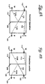
- Figure 4a shows the normal operation of a switch in an optical network utilising 1 + 1 protection switching.
- the signal 113 from the incoming working path is directed to reflect off the surface 200 such that a portion of the signal 113A is directed to the outgoing working path 114.
- the fraction of the signal 113B transmitted through the window 200 is output to the outgoing protection path 124.
- Any incoming signal 123 from the incoming protection path 122 is directed to an optical sink so that the optical signal 123 does not cause any interference with any of the other outputs.
- the optical signal 123 from the protect path is used to provide both outputs as shown in figure 4B.
- the signal 113 from the working path is directed to an optical sink (not shown).
- the optical signal 123 from the protect path 122 is directed to reflect off the surface 200, with the reflective portion 123A being directed to the protect path output 124 and the transmitted portion 123B being directed to the working path output 114.
- a network incorporating such a protection scheme would comprise at least two nodes linked by diverse main and optical protection paths, at least one of the nodes coupling selected data onto the main path and the protection path for reception by the other of the nodes.
- a switching arrangement is provided between the two nodes for enabling switching of a signal on one of the paths, such that traffic can cross between the main and protection paths at the location of the or each switching arrangement.
- This arrangement is quite often termed a ladder arrangement, as the main and protection optical paths are analogous to the uprights on a ladder, with the switching arrangements between the main and protection paths being analogous to the rungs of a ladder.
- Such a scheme provides a communications network between two nodes, in which 1 + 1 protection is provided, and is supplemented by control of the switching signals between the working and the protection paths of the 1 + 1 protection at intermediate locations.
- This enables a sinuous communication path to be established, so that communication can be maintained even the event of multiple failures affecting both the working and protection paths, when such failures occur in different intermediate stands of the network.
- the defined main and protection paths can remain fixed during communication, so that switching can be carried out with low computation effort.
- each segment may have a plurality of inputs or outputs as desired, with suitable beamsteering means arranged to provide the desired connectivity between the inputs and outputs of the respected segments.
- the window 200 in the preferred embodiment is 50% reflective and 50% transmissive, it will be appreciated that any desired ratio of transmissive to reflective characteristics could be utilised.
- the medium forming the window could comprise a controllably variable reflective substance, such that the reflective and transmissive characteristics are altered as required.
- one or more optical amplifying regions could be incorporated into the switch so as to amplify the optical signals, either before or after the signal has been incident upon the surface 200. If desired, such an amplifying region could comprise a portion of the surface 200.
- optical and light should be understood as pertaining not only to the visible part of the electromagnetic spectrum, but also to the infra-red and ultra-violet parts that bound the visible part.
Landscapes
- Physics & Mathematics (AREA)
- General Physics & Mathematics (AREA)
- Optics & Photonics (AREA)
- Optical Communication System (AREA)
- Use Of Switch Circuits For Exchanges And Methods Of Control Of Multiplex Exchanges (AREA)
- Mechanical Light Control Or Optical Switches (AREA)
Abstract
Description
Claims (14)
- An optical switch characterised in that it comprises two segments (110,120) at least partially separated by a surface (200) that is partially reflective and partially transmissive to optical signals being switched,
each segment having at least one optical input and at least one optical output, the segments being arranged such that an optical signal can be switched from said input to said output by reflection from said surface, with the optical signal that is generated by transmission through said surface being directed to an output of the other segment. - A switch as claimed in claim 1, wherein each segment comprises a plurality of said inputs and a plurality of said outputs.
- A switch as claimed in any one of claims 1-2, wherein said surface is substantially 50% reflective and 50% transmissive in respect of the wavelength of the optical signal being switched.
- An optical switch as claimed in any one of claims 1-3, further comprising beam steering means arranged to controllably switch the optical signal from said inputs to said outputs.
- A switch as claimed in any one of claims 1-4, wherein each segment further comprises electrical control means arranged to control the operation of the switch, with each segment being electrically separate.
- A switch as claimed in any one of claims 1-5, further comprising at least one optically amplifying region arranged to amplify optical signals within said switch.
- A switch as claimed in claim 6, wherein said amplifying region is coupled to said surface so as to amplify optical signals being transmitted through said surface.
- A switch as claimed in any one of claims 1-7, wherein the input and output positions of one of the segments are substantially the mirror image of the input and output positions of the second segment.
- A telecommunications network arranged to transmit optical signals characterised in that it comprises a switch as claimed in any one of claims 1-8.
- A network as claimed in claim 9, comprising at least one working and one protect channel each arranged to carry optical signals, with the optical signal of the working channel being input to the first segment of the switch, and the protect channel being input to the other segment.
- A telecommunications network arranged to transmit optical signals and comprising a plurality of switches as claimed in any one of claims 1-8, wherein said switches are arranged to provide ladder type protection.
- A computer program arranged to control the operation of a switch as claimed in any one of claims 1-8.
- A segment (110) for an optical switch characterised in that it comprises a surface (200) that is partially reflective and partially transmissive, the segment comprising at least one input (112) and at least one output (114) and being arranged to transmit optical signals from said input to said output by reflection from the surface.
- A method of switching an optical signal from at least one input (112) to at least one output characterised in that switching is performed by reflecting the signal from a surface that is partially transmissive and partially reflective, with the portion of the optical signal that is transmitted through the surface being directed to a further output.
Applications Claiming Priority (2)
| Application Number | Priority Date | Filing Date | Title |
|---|---|---|---|
| US750871 | 1985-07-01 | ||
| US09/750,871 US6594413B2 (en) | 2000-12-28 | 2000-12-28 | Optical switching device |
Publications (2)
| Publication Number | Publication Date |
|---|---|
| EP1239696A2 true EP1239696A2 (en) | 2002-09-11 |
| EP1239696A3 EP1239696A3 (en) | 2008-02-27 |
Family
ID=25019486
Family Applications (1)
| Application Number | Title | Priority Date | Filing Date |
|---|---|---|---|
| EP01310659A Withdrawn EP1239696A3 (en) | 2000-12-28 | 2001-12-20 | Optical switching device |
Country Status (2)
| Country | Link |
|---|---|
| US (1) | US6594413B2 (en) |
| EP (1) | EP1239696A3 (en) |
Family Cites Families (11)
| Publication number | Priority date | Publication date | Assignee | Title |
|---|---|---|---|---|
| US4504121A (en) * | 1981-11-02 | 1985-03-12 | Gte Laboratories Incorporated | Interferometric multimode fiber optic switch and modulator |
| US5504772A (en) * | 1994-09-09 | 1996-04-02 | Deacon Research | Laser with electrically-controlled grating reflector |
| US5515361A (en) * | 1995-02-24 | 1996-05-07 | International Business Machines Corporation | Link monitoring and management in optical star networks |
| NL1001841C2 (en) * | 1995-12-07 | 1997-06-10 | Nederland Ptt | Optical coupling device and optical switch for use in the optical coupling device. |
| US6487014B2 (en) * | 1996-08-12 | 2002-11-26 | National Research Council Of Canada | High isolation optical switch, isolator or circulator having thin film polarizing beam-splitters |
| US5943454A (en) * | 1997-08-15 | 1999-08-24 | Lucent Technologies, Inc. | Freespace optical bypass-exchange switch |
| US5982554A (en) * | 1997-12-31 | 1999-11-09 | At&T Corp | Bridging apparatus and method for an optical crossconnect device |
| US6320993B1 (en) * | 1998-06-05 | 2001-11-20 | Astarte Fiber Networks, Inc. | Optical switch pathway configuration using control signals |
| US6160665A (en) * | 1999-06-04 | 2000-12-12 | Chorum Technologies Inc. | High extinction ratio polarization beamsplitter |
| US6493479B1 (en) * | 2000-04-07 | 2002-12-10 | Nortel Networks Limited | Crosspoint switch protection using additional switching elements to provide alternate paths |
| US6337760B1 (en) * | 2000-07-17 | 2002-01-08 | Reflectivity, Inc. | Encapsulated multi-directional light beam steering device |
-
2000
- 2000-12-28 US US09/750,871 patent/US6594413B2/en not_active Expired - Lifetime
-
2001
- 2001-12-20 EP EP01310659A patent/EP1239696A3/en not_active Withdrawn
Also Published As
| Publication number | Publication date |
|---|---|
| EP1239696A3 (en) | 2008-02-27 |
| US20020085798A1 (en) | 2002-07-04 |
| US6594413B2 (en) | 2003-07-15 |
Similar Documents
| Publication | Publication Date | Title |
|---|---|---|
| US6195186B1 (en) | Optical WDM ring network | |
| Elrefaie | Multiwavelength survivable ring network architectures | |
| US5777761A (en) | System and method for photonic facility and line protection switching using wavelength translation | |
| US20040190901A1 (en) | Bi-directional optical network element and its control protocols for WDM rings | |
| KR20030083742A (en) | Method and apparatus for transferring wdm signals between different wdm communications systems in optically transparent manner | |
| US4815803A (en) | Optical signal network with node by-pass switching capability | |
| US11888583B2 (en) | Integrated 3-way branching unit switch module having small footprint | |
| EP1064739B1 (en) | Protection of wdm-channels | |
| US6289148B1 (en) | Free-space micro-mirror wavelength add/drop multiplexers with full connectivity for two-fiber ring networks | |
| US6771852B2 (en) | Two-fiber optical shared protection ring with a bi-directional 4×4 optical switch fabric | |
| US6396969B1 (en) | Distributed optical switching device | |
| EP1014613A2 (en) | Shared optical protection in an optical communications network | |
| Helkey et al. | Design of large, MEMS-based photonic switches | |
| EP1143760A2 (en) | Crosspoint switch protection | |
| US6594413B2 (en) | Optical switching device | |
| US6643423B2 (en) | System and method for bridge and roll in a photonic switch | |
| US6407838B1 (en) | Reconfigurable multi-add/drop module for optical communications | |
| US7187865B2 (en) | Hybrid photonic/electronic switching in a multi-channel network | |
| GB2304482A (en) | Optical branching and transmission line switching | |
| JPH11344638A (en) | Ring coupler for optical networks | |
| US20030039433A1 (en) | Optical communication circuit | |
| JPH05130034A (en) | Star ring communication equipment | |
| US20030147356A1 (en) | High speed healing ring for optical transport networks | |
| US7133612B1 (en) | Bidirectional WDM transmission system having transmission format for reducing adverse effects of filter concatonation | |
| US6501575B2 (en) | Routing in a WDM system |
Legal Events
| Date | Code | Title | Description |
|---|---|---|---|
| PUAI | Public reference made under article 153(3) epc to a published international application that has entered the european phase |
Free format text: ORIGINAL CODE: 0009012 |
|
| AK | Designated contracting states |
Kind code of ref document: A2 Designated state(s): AT BE CH CY DE DK ES FI FR GB GR IE IT LI LU MC NL PT SE TR |
|
| AX | Request for extension of the european patent |
Free format text: AL;LT;LV;MK;RO;SI |
|
| PUAL | Search report despatched |
Free format text: ORIGINAL CODE: 0009013 |
|
| AK | Designated contracting states |
Kind code of ref document: A3 Designated state(s): AT BE CH CY DE DK ES FI FR GB GR IE IT LI LU MC NL PT SE TR |
|
| AX | Request for extension of the european patent |
Extension state: AL LT LV MK RO SI |
|
| 17P | Request for examination filed |
Effective date: 20080827 |
|
| AKX | Designation fees paid |
Designated state(s): DE FR GB |
|
| 17Q | First examination report despatched |
Effective date: 20090323 |
|
| STAA | Information on the status of an ep patent application or granted ep patent |
Free format text: STATUS: THE APPLICATION IS DEEMED TO BE WITHDRAWN |
|
| 18D | Application deemed to be withdrawn |
Effective date: 20090804 |