EP1239587A2 - The determination of a reference value for automatic gain control of a receiver communicating with a packet switched communication network - Google Patents
The determination of a reference value for automatic gain control of a receiver communicating with a packet switched communication network Download PDFInfo
- Publication number
- EP1239587A2 EP1239587A2 EP02396024A EP02396024A EP1239587A2 EP 1239587 A2 EP1239587 A2 EP 1239587A2 EP 02396024 A EP02396024 A EP 02396024A EP 02396024 A EP02396024 A EP 02396024A EP 1239587 A2 EP1239587 A2 EP 1239587A2
- Authority
- EP
- European Patent Office
- Prior art keywords
- blocks
- radio blocks
- transmission power
- received
- signal
- Prior art date
- Legal status (The legal status is an assumption and is not a legal conclusion. Google has not performed a legal analysis and makes no representation as to the accuracy of the status listed.)
- Granted
Links
Images


Classifications
-
- H—ELECTRICITY
- H04—ELECTRIC COMMUNICATION TECHNIQUE
- H04L—TRANSMISSION OF DIGITAL INFORMATION, e.g. TELEGRAPHIC COMMUNICATION
- H04L1/00—Arrangements for detecting or preventing errors in the information received
- H04L1/0001—Systems modifying transmission characteristics according to link quality, e.g. power backoff
-
- H—ELECTRICITY
- H03—ELECTRONIC CIRCUITRY
- H03G—CONTROL OF AMPLIFICATION
- H03G3/00—Gain control in amplifiers or frequency changers
- H03G3/20—Automatic control
- H03G3/30—Automatic control in amplifiers having semiconductor devices
- H03G3/3052—Automatic control in amplifiers having semiconductor devices in bandpass amplifiers (H.F. or I.F.) or in frequency-changers used in a (super)heterodyne receiver
Definitions
- the present invention relates to a method according to the preamble of the appended claim 1.
- the invention relates to a device according to the preamble of the appended claim 24.
- a wireless communication system generally refers to a communication system which makes a wireless data transmission connection possible between a wireless communication device (MS, mobile station) and stationary parts of the system, the user of the wireless communication device moving within the operating range of the system.
- a typical system is a public land mobile network PLMN.
- a majority of wireless communication systems belongs to so-called second-generation mobile communication systems, of which an example to be mentioned is the widely known circuit switched GSM mobile communication system (Global System for Mobile Telecommunications).
- GSM mobile communication system Global System for Mobile Telecommunications
- the present invention is particularly suitable for mobile communication systems under development.
- the GPRS system General Packet Radio Service
- the invention can also be applied in other systems which are based on packet systems, such as the GPRS system, or which utilize it (UMTS, Universal Mobile Telecommunication System).
- the system consists, in a known way, of several mobile stations (MS) applying the system, such as mobile phones, and a stationary base station subsystem (BSS).
- This base station subsystem normally consists of several base transceiver stations (BTS) distributed over a geographical area, and each base station serves a cell which consists of at least a part of this geographical area.
- BTS base transceiver stations
- communication between communication devices is carried on logical radio channels.
- a packet switched system based on the GSM system the GSM GPRS system, makes communication more efficient, since the same logical radio channel can be used by several different mobile subscribers. Data is transmitted only when necessary, and the logical radio channel is not allocated to communication between one mobile station and one base station only.
- the operating environment of the system is known as such and is widely defined in the ETSI standards, wherein a more detailed description will not be necessary.
- the MS will first log in the network (GPRS attach). The login forms a logical link between the wireless communication device and the serving GPRS support node SGSN.
- the trouble-proof operation of the communication network and the efficient utilization of the available resources are only possible, if the power levels used in the transmissions by e.g. the base stations are as optimal as possible. In addition to this, demands are continuously set for the power consumption of the mobile station itself.
- the basic idea of the GPRS system is to apply packet switched resource allocation, wherein resources, e.g. a logical radio channel, are allocated when there is a need to transmit and receive data and information.
- resources e.g. a logical radio channel
- the GPRS is designed to support applications which utilize discontinuous data transmission containing, intermittently, even large quantities of data.
- the allocation of channels is flexible, and 1 to 8 time slots of a channel, i.e. 1 to 8 physical channels, can be allocated to each wireless communication device within the scope of a TDMA frame.
- TDMA Time Division Multiple Access
- U communication uplink, i.e. communication from the mobile station to the base station
- D communication downlink, i.e. communication from the base station to the mobile station
- U communication uplink, i.e. communication from the mobile station to the base station
- D communication downlink, i.e. communication from the base station to the mobile station
- U communication uplink, i.e. communication from the mobile station to the base station
- D communication downlink, i.e. communication from the base station to the mobile station
- TCH traffic channels
- the traffic channels are primarily used for the transmission of speech and data, and the control channels are used for signalling between the BTS and the MS.
- BCCH Broadcast Control Channel
- This information relates, for example, to the frequencies used by the cell in question and by the adjacent cell, as well as to the surrounding cells, frequency hopping, channel combinations, and paging groups.
- a physical channel so-called packet data channel PDCH
- PDCH packet data channel
- the logical channels contained in the PDCH channel are collected into a frame structure (Multiframe) consisting of repeatedly transmitted 52 TDMA frames (20) which are divided (PCDH/F, Full rate PDCH channel) further into 12 successive blocks (radio blocks), each comprising four frames (TDMA FRAME) as well as four extra frames (IDLE FRAME).
- the blocks 10 are indicated by blocks B0 to B11, respectively, as shown in Fig. 1.
- the idle frames are also indicated with the reference X. In D communication, these can be used for signalling.
- the blocks 10 are further divided into the following parts shown in Fig. 2: MAC header (Medium Access Control Header), RLC data block (Radio Link Control Data Block) or RLC/MAC control block, and BCS block (Block Check Sequence).
- the RLC data block contains an RLC header and RLC data.
- the MAC header also comprises a USF field (Uplink State Flag).
- LLC, RLC and MAC refer to different levels (protocol layers) in a protocol structure according to an OSI model (Open Structured Interface), known as such, which are described in more detail in the ETSI standard specifications.
- a temporary flow identifier TFI is used in the data header.
- Each RLC header contains a TFI which is used to indicate the blocks addressed to a specific, given mobile station MS.
- TFI Temporal flow identifier
- the MS is informed of the allocated blocks, during which transmission and reception is possible.
- the connection is set up either by means of a packet channel request PCR, which is transmitted by the mobile station to request for resources from the base transceiver station on the packet random access channel PRACH, or by means of a packet paging request PPR transmitted by the base transceiver station.
- the resources allocated for data transmission are indicated, for example, by means of a packet uplink assignment PUA or a packet downlink assignment PDA, containing e.g. a list of the available PDCH channels, the value of the USF field to be used, and a determined individual temporary flow indicator TFI which is added to each RLC block used in the communication.
- the mobile stations must be continuously ready for packet communication (Temporary Block Flow, TBF), wherein they must quickly shift from the so-called idle mode to the so-called packet transfer mode.
- the mobile communication device In digital TDMA systems, such as the GSM system, the mobile communication device continuously measures the signal strength on radio channels of the serving base station and the adjacent base stations, and transmits a measuring report to the base station.
- the measurements taken by the mobile communication device are typically, and in a way known as such, related to power control used in D communication, cell reselection or handover.
- Power control refers, for example, to the transmission power level used by the BTS for transmitting a radio signal to the MS.
- the MS maintains information about the received signal strength of the used BCCH radio channel by means of an average.
- This information and the calculated C parameter are utilized in decisions related to cell reselection.
- the signal strength is measured in units of dBm.
- the averaging is based on at least five, normally six samples taken from the radio channel during one multiframe structure (52 TDMA frames).
- the rules for power control, the measurement, the calculation of the C value, and the modes A and B for the power control which will be described in the following, are also defined in more detail for example in the ETSI specification (European Telecommunications Standards Institute) 3GPP TS 05.08 V8.6.0 (2000-09), particularly in the chapter: 10.2.
- RF Power Control which is incorporated herein as a reference.
- the present invention for calculating the ARR parameter utilizes these same samples SS n of the received signal level, Rx level.
- AGC Automatic Gain Control
- the signal levels are also changed as a result of BTS power control in D communication.
- the operation of the AGC is based on tracing the Rx levels of the received signal, when the MS is receiving on the PDTCH channel. Both the PDTCH and the BCCH channels are traced.
- the MS must be capable of tracing changes in the received downlink signal in order to be able to interpret the information of the block, for example the TFI data, so that the MS can determine whether the block is addressed to it for reception.
- the aim is to set the gain level of the received analog RF signal before the AD (analog-to-digital) conversion and on a reference level suitable for input in the receiver of the MS.
- the dynamic range of the receiver is typically defined to be restricted above (15 dB) and below (20 dB) a specific reference level.
- the difference in the power levels between the frames can be as great as 30 dB.
- constant power control is used for D communication on PDCH channels, which are used, for example, as PBCCH and PCCCH control channels.
- the power level can be lower on the PCCCH than on the BCCH channel (Broadcast Control Channel), the difference (Pb) being indicated on the PBCCH channel.
- the PTCCH/D channel Packet Transfer Control Channel
- the power level is always the same during the bursts (4 bursts) of a single radio block.
- Mode A the variation in the output power of the BTS is limited
- Mode B the whole range of variation of the output power of the BTS is in use.
- the used mode is indicated to the MS in connection with resource allocation (so-called Assignment message).
- P0 the so-called P0 parameter is used, which indicates the power reduction compared to the BCCH channel whose carrier can be continuously traced.
- the parameter P0 is also indicated in the Assignment message. The used mode and the value of P0 are not changed without new assignment messages when the MS is in packet transfer mode.
- Each block of the PDTCH/D channel contains a PR field in the MAC header, to indicate the power level of said block, if it is in use and power control is used.
- PR mode A (appended Table 1), the PR value is calculated on the basis of the output power level used by the BTS, when the block is addressed to a specific receiving MS. A P0 value is determined for each MS.
- the PR value is calculated in relation to the P0 value of the MS in question.
- PR mode B (appended Table 2), the same power level is used for each block and for each mobile station on the same PDCH channel communicating (TBF) with the BTS.
- the P0 value indicates the power level of the first block on the PDCH, and the PR value is calculated in relation to the level of the BCCH.
- the BTS transmits to the mobile stations in packet transfer mode at least one reference block, which conforms to the used mode, at certain intervals (78 TDMA frames).
- the reference block is also transmitted when the power control is not in use.
- the reference block contains a usable PR field.
- PR Mode A valid, usable blocks only include blocks addressed to the MS in question and having a valid PR value, but in PR Mode B, the block does not need to be addressed to the MS in question.
- the method according to the invention is presented in the independent claim 1.
- the device according to the invention is presented in the independent claim 24.
- a reference value is continuously determined, which will, in this description, be referred to as the parameter AGC_REF_RXLEX (ARR-parameter), which thus describes the power level, Rx level, of the received signal.
- ARR-parameter the parameter which thus describes the power level, Rx level, of the received signal.
- the invention is based on facts to be presented in the following.
- the Rx level of those blocks will be calculated, which can be used as valid AGC reference blocks according to the invention. This applies also to a situation in which no power control is used.
- the valid blocks are determined on the basis of the PR fields (and, if necessary, also the TFI fields) of the block. All the blocks which have been correctly (flawlessly CRC checking passes) received can be used as valid reference blocks, when D power control is not used by the BTS.
- the values of the Rx levels of these received blocks are averaged (within time), particularly by using a filter with a variable length.
- the period of time used for averaging remains substantially constant.
- a filter with a variable length makes it possible to do a quick adaptation to the correct channel RSSI level in situations in which the number and interval of received reference blocks are not known beforehand and in which the RSSI level varies quickly.
- the carrier level of the BCCH channel of the serving BTS is traced.
- the carrier is traced at determined intervals, and the samples are averaged with respect to time. If the MS does not, for any reason, receive valid reference blocks within a set time (particularly 78 TDMA frames), the BCCH carrier level is used as a help to estimate the PDTCH carrier level for the AGC.
- the use of the BCCH channel as an auxiliary reference supports the function of the AGC particularly in situations, in which the MS, for any reason, cannot correctly decode the blocks transmitted by the BTS (so-called CRC check-up) and, therefore, does not receive sufficiently valid reference blocks.
- the AGC of traffic channels has been possible with simpler algorithms, because there is always communication on e.g. the SACCH channel (Slow Associated Control Channel) and in the SID frame (Silence Indicator) and, on the basis of the frame number, the MS knows better their moment of time, wherein the Rx level of the bursts of these frames can be used for implementing the AGC algorithm.
- SACCH Small Associated Control Channel
- SID frame Silence Indicator
- the Rx level is traced for determining the reference Rx level for the AGC.
- the samples used are the same as, for example, in the calculation of the C value.
- a difference is, however, the so-called forgetting factor in the calculation, that is, 1 / BCCH_RA_FILT_LEN, which can now be freely selected.
- the factor is set by the network.
- the calculation of BCCH_RA_n is started/initialized, when the MS starts to prepare the beginning of data transmission and is transferred from the DRX state to the non-DRX state, and is maintained as long as the MS is in the non-DRX state.
- the aim is to determine the ARR parameter which corresponds to the transmission power level of the BTS on the level BCCH-P0.
- the network must transmit a reference block at certain intervals (at least once within a sequence of 78 TDMA frames).
- the ARR parameter is calculated by using the running average of the Rx levels of the blocks in question.
- the BTS transmission power of the blocks is known by means of the PR field, and the measured Rx levels of the reference blocks can be mapped to correspond to the transmission power on the level BCCH-P0.
- the length, in time, of the sequence of calculating the average is kept substantially constant by changing the filter length of the calculation of the average, which is dependent on the frequency of occurrence of AGC reference blocks which is, for example, 78 TDMA frames. If the MS does not, for any reason, receive reference blocks during 78 TDMA frames, the ARR parameter value is adapted to the level BCCH_RA_n-P0.
- the reference Rx level intended for the AGC is traced in the PDTCH configuration, that is, when the MS is in the GPRS transfer state.
- the gain is calculated for the next beginning block period (78 frames), after AGC_REF_RXLEV has first been updated by using the algorithm.
- PR Mode A all the correctly received RLC blocks addressed to the MS and having a valid PR field can be used as reference blocks.
- PR Mode B all the correctly received RLC blocks having a valid PR field can be used as reference blocks.
- the value AGC_REF_RXLEV is set to the value BCCH_RA_n-P0.
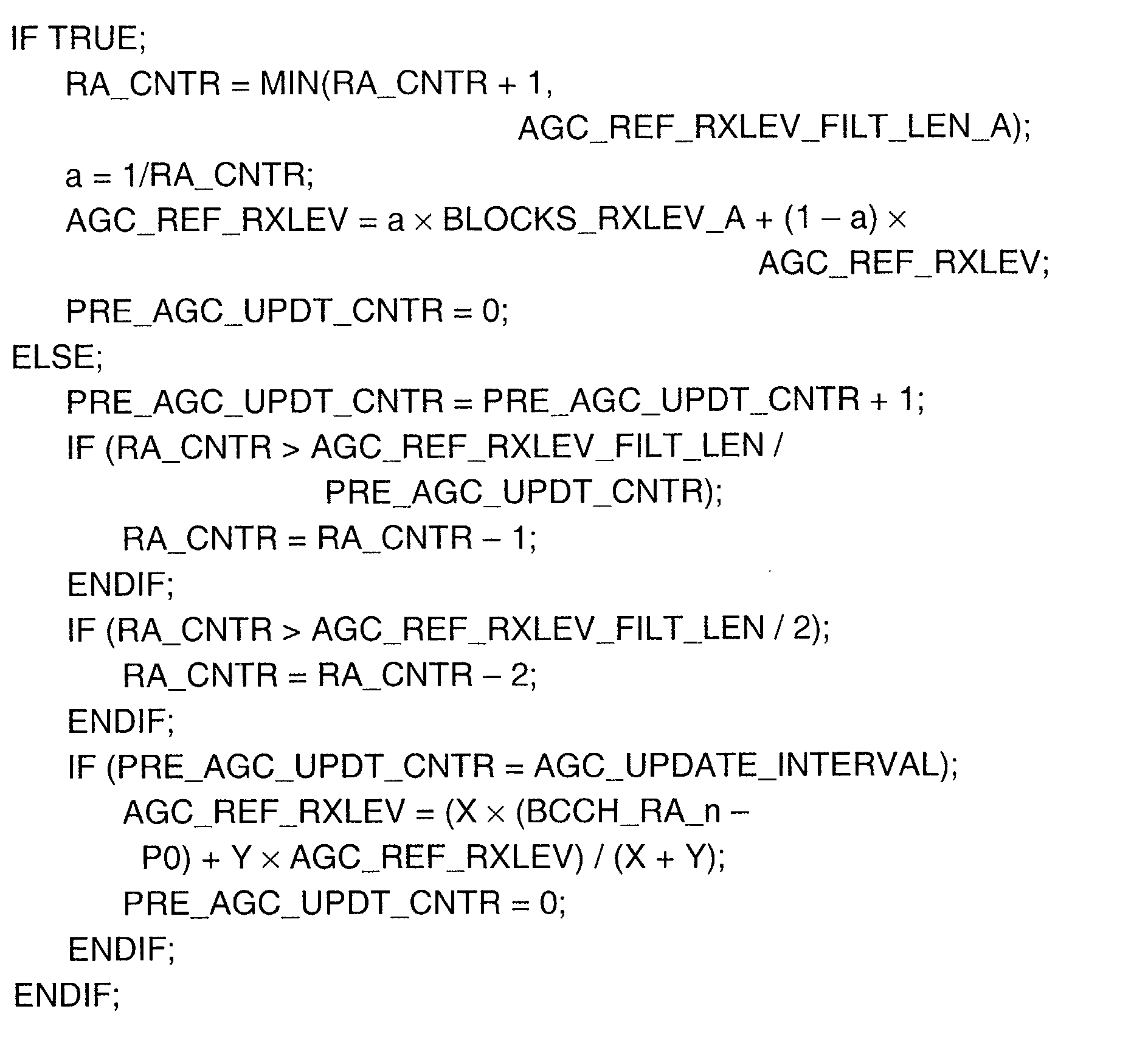
- REF_RXLEV_FILT_LEN_A used in the algorithm is the filter length for the calculation of the running average in Mode A.
- AGC_UPDATE_INTERVAL is an interval in blocks, indicating how often AGC_REF_RXLEV must be updated, if MS has not received blocks addressed to it. At present, the interval is 78 TDMA frames, or 18 radio blocks.
- X and Y are constants for weighting the level BCCH_RA_n in the estimation of the Rx level, when no valid reference blocks have been received.
- the variable BLOCKS_RXLEVS_A used in the algorithm is the measured average of the Rx level of the reference blocks in units of dBm and during the preceding block period as well as compensated on the basis of data on the PR field, to correspond to the level BCCH-P0.
- the Rx level of the block is compensated for by adding to it 1, 5 or 9 dB, depending on the value of the PR field (00, 01, 10).
- the variable has a valid value only when the MS has received reference blocks during the preceding block period.
- MAX_BLK_RXLEV is the maximum Rx level of the block after the latest valid reference block.
- RA_CNTR is a counter for the calculation of the running average, having an initial value of zero.
- P0 is the P0 value (dB) given by the network.
- PRE_AGC_UPDT_CNTR is a counter indicating how many blocks ago the preceding value AGC_REF_RXLEV was updated.
- a temporary variable a is used to transmit the forgetting factor for the calculation of the running average.
- the pseudo code of the algorithm will be presented, to illustrate the details and operating principles of the invention.
- the algorithm is always performed once at the end of a block period, after the received blocks have been decoded. It should be noted that the pseudo codes presented in the description are combined, if necessary, to form an entity and, if necessary, it is supplemented with a pseudo code to implement other operations according to the description.
- the IF block it is first examined, if reference blocks for the AGC were received during the preceding block period (TRUE).
- AGC_REF_RXLEV BCCH_RA_n-P0.
- AGC_REF_RXLEV is calculated as a running average from the RLC reference blocks, by using a filter with a variable length in the calculation of the running average.
- PR Mode B all the blocks having a PR field are valid.
- PR Mode A only the blocks which have a PR field and which are addressed to the MS in question, are valid.
- Mode A PR Mode B
- other blocks than own blocks are available for calculating and describing the running average.
- the difference between the calculated and the real Rx levels can be, at its worst, 6 dB, and the compensation is thus less accurate than in Mode A.
- Another difference to Mode A is that if the MS does not receive the reference block during the predetermined 78 TDMA frames, the ARR parameter is updated by using the change that took place in the value BCCH_RA and after the last received reference block.
- the gain is calculated for the next beginning block period after AGC_REF_RXLEV has been updated by using the algorithm. All the correctly received blocks which are addressed to the MS and which have a valid PR field can be used as reference blocks for the AGC. Before the beginning of the PDTCH configuration, the value AGC_REF_RXLEV is set to the value BCCH_RA_n-P0.
- the constant REF_RXLEV_FILT_LEN_B used in the algorithm is the filter length for filtering the running average (i.e. the inverse value of the forgetting factor) and for calculating it in Mode B.
- the variable BLOCKS_RXLEVS_B used in the algorithm is the measured average of the Rx level of the reference blocks in the preceding block period, in units of dBm, wherein the blocks which are not addressed to the MS are compensated for by using the PR value, if the PR value differs from its own PR value which was used last.
- the compensated Rx level (dBm) is obtained by reducing from the PR value the last own PR value, by multiplying the result with the constant 8 (dB), and by adding the result to the Rx level.
- the constant 8 is obtained from the difference between two successive PR values of the Rx level.
- the principle is that compensation is not performed for own blocks and for those foreign blocks which have the same PR value as in the latest own block. The compensation is only performed for foreign blocks having a different PR value.
- the use of foreign blocks as a reference is only applied in PR Mode B. The tracing of the ARR value is described to correspond to the own transmission which is performed on some level BCCH-X. In PR Mode B, all the blocks with a PR field are suitable for use as references. In PR Mode A, only the blocks addressed to the MS (and containing a PR field) are valid.
- the BTS will thus transmit at a constant power level BCCH-X, in which X is normally the Pb value, but it may also differ from this.
- BCCH_RA_n-Pb the value AGC_REF_RXLEV is set to the value BCCH_RA_n-Pb.
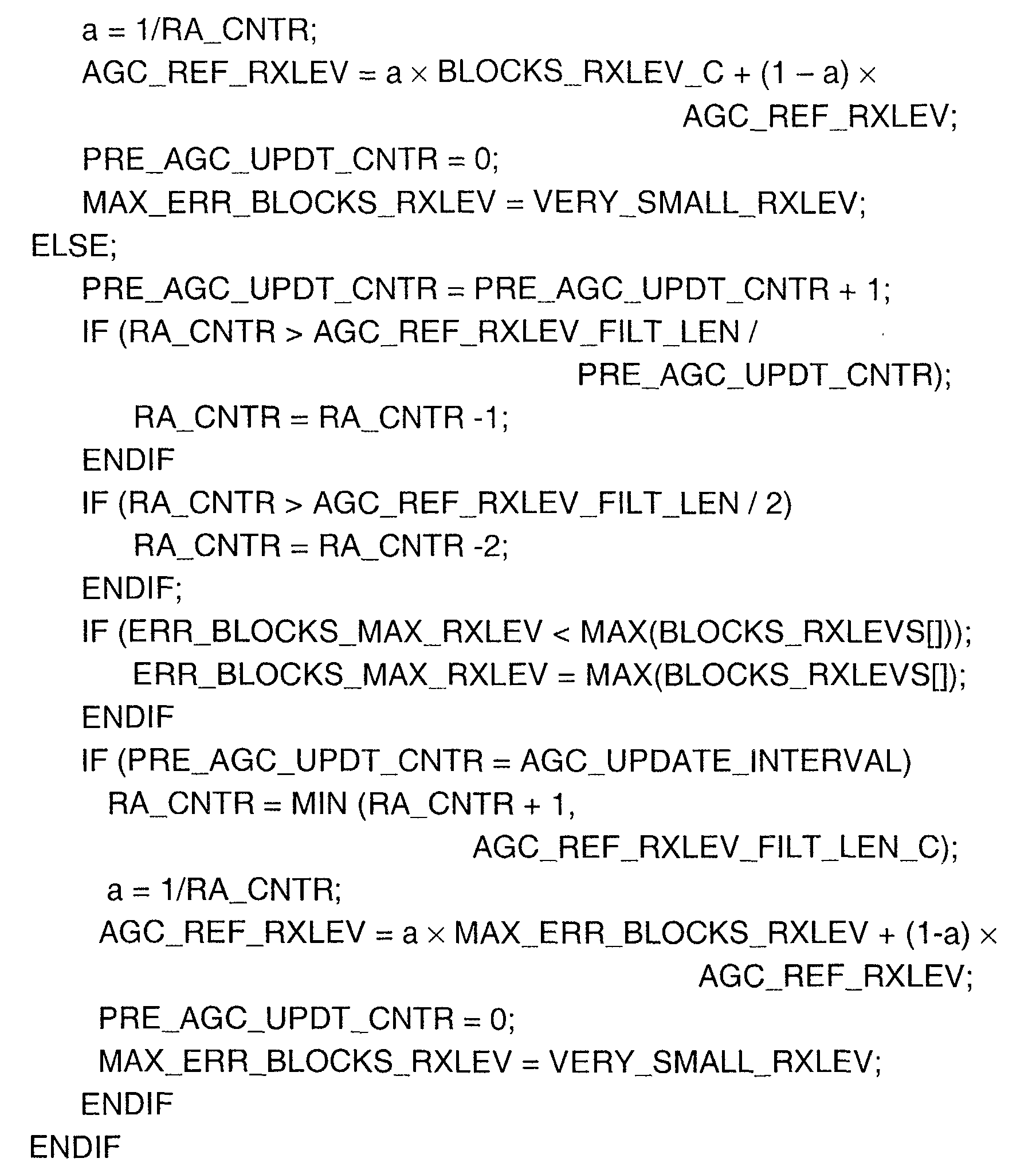
- the ARR parameter is calculated by using a running average and a filter with a variable length, as in Modes A and B. If the MS does not receive reference blocks during a period comprising 78 TDMA frames, AGC_REF_RXLEV is updated by using the maximum Rx level of an incorrect block, which is thus a sample for calculating the average.
- the reference Rx level intended for the AGC is traced in the PDTCH configuration, that is, when the MS is in the GPRS transfer state.
- the gain is calculated for the next beginning block sequence, after AGC_REF_RXLEV has first been updated by using an algorithm. All correctly received blocks can be used as reference blocks.
- the constant REF_RXLEV_FILT_LEN_C used in the algorithm is the filter length for filtering the running average.
- VERY_SMALL_RXLEV is a very small Rx level, for example -120 dBm.
- the variable BLOCKS_RXLEVS[] is a table of the Rx levels (in units of dBm) of the blocks received at different allocated time periods (max 8), irrespective of the fact whether the block was correctly received.
- the parameter BLOCKS_RXLEVS_C is the average from the Rx levels of the blocks (reference blocks) of the table which were encoded correctly.
- the parameter ERR_BLOCKS_MAX_RXLEV is the maximum average of the Rx level for the blocks which were encoded incorrectly. At the beginning of the PDCH, this value is set to VERY_SMALL_RXLEV.
- clipping control which is necessary to be able to react to very fast changes in the Rx level in Modes A and B. If the properties of the radio channel change very randomly so that very fast changes take place in the Rx level, the tracing of the running reference Rx level will not be sufficient.
- the control will first determine a lower limit and an upper limit for the receiving window of the gained and AD converted signal of the MS, between which the Rx levels of the received bursts should be when they belong to valid blocks. Clipping will take place, if the signal level of a single burst exceeds the upper limit, and inverse clipping will take place, if the average of the Rx levels of the two preceding bursts is below the lower limit.
- the gain is immediately corrected to the right level, to receive other bursts of the block.
- the gain can be adapted once or several times but normally only once during a block period.
- the block (or blocks) After the block (or blocks) has been received and decoded, it is checked if the burst (or bursts) is valid for clipping control, that is, if the burst which caused the clipping belongs to a block which is a block valid as a reference according to the power control modes. If the clipped block is valid, the ARR parameter is updated according to the principles to be described in the following.
- the pseudo code of the clipping algorithm will be presented.
- the algorithm is performed before the algorithms described above, or at the beginning of the first IF unit.
- the IF block it is first examined, if cutting has taken place (TRUE).
- TRUE cutting has taken place
- Mode A and when power control is not in use, it is possible to use all blocks for the clipping control, including blocks which have been received incorrectly, but in Mode B, addressed blocks only.
- Mode B In the inverse clipping algorithm, it is only possible to use AGC reference blocks which are valid according to the power control modes (including also the alternative with no power control).
- the ARR is always corrected after clipping or inverse clipping, for a block valid for clipping control.
- the value of the constant CLIP_CORRECTION_UP or CLIP_CORRECTION_DOWN (in dB) also tells how much the ARR value is corrected when clipping up or down takes place.
- the pseudo code is presented as follows. The algorithm is performed before the algorithms described above, or at the beginning of the first IF unit. In the IF block, it is first examined, if cutting has taken place (TRUE).
- the allocation of channels is very flexible; for example, 1 to 2 time slots of a channel, or 1 to 8 logical channels, can be allocated to each wireless communication device MS within the scope of a TDMA frame.
- the gain is set the same for each allocated time slot and, at the beginning of the block, the required gain is calculated from the ARR parameter.
- the gains for different time slots may thus differ from each other during the rest of the block period.
- the gain is determined again from the ARR value and is set the same for each time slot.
Landscapes
- Engineering & Computer Science (AREA)
- Quality & Reliability (AREA)
- Computer Networks & Wireless Communication (AREA)
- Signal Processing (AREA)
- Mobile Radio Communication Systems (AREA)
- Control Of Amplification And Gain Control (AREA)
- Circuits Of Receivers In General (AREA)
Abstract
Description
| Bits | Power reduction, Mode A |
| 0 0 | 0 to 2 dB lower than BCCH level - P0 |
| 0 1 | 4 to 6 dB lower than BCCH level - P0 |
| 1 0 | 8 to 10 dB lower than BCCH level - P0 |
| 1 1 | Not usable |
| Bits | Power reduction, PR Mode B |
| 0 0 | 0 to 6 dB lower than BCCH level |
| 0 1 | 8 to 14 dB lower than BCCH level |
| 1 0 | 16 to 22 dB lower than BCCH level |
| 11 | 24 to 30 dB lower than BCCH level |
- Fig. 1
- shows a frame structure of prior art, particularly the frame structure of the GPRS system, and
- Fig. 2
- shows a block structure of prior art, particularly the structure of a radio block in the GPRS system.




Claims (27)
- A method for determining a reference level for automatic gain control of a radio frequency signal to be received, particularly having a varying strength, in which method radio blocks (10) are received on a logical packet data traffic channel of a signal, which radio blocks (10) have been transmitted with a predetermined transmission power and by using a predetermined way of controlling the transmission power, characterized in that said reference level is continuously determined on the basis of correctly received, i.e., valid radio blocks (10), wherein the reference level is corrected on the basis of the signal strength measured during the reception of each valid radio block.
- A method according to claim 1, characterized in that the reference level is corrected by calculating its running average with respect to time.
- A method according to claim 2, characterized in that the running average is calculated by using filtering with a variable length, wherein the period, during which the average is calculated, is preferably kept constant, depending on the frequency of occurrence of valid radio blocks.
- A method according to claim 2 or 3, characterized in that by using the running average, a predetermined number of valid radio blocks is calculated as a forgetting factor.
- A method according to any of the claims 1 to 4, characterized in that a signal of a broadcasting channel is received, which is transmitted at a predetermined constant transmission power, and that the reference level is corrected on the basis of the signal strength measured during the reception of this signal, if no valid radio blocks have been received during the predetermined period of time.
- A method according to claim 5, characterized in that the running average of the signal strength of the broadcasting channel is calculated with respect to time.
- A method according to claim 6, characterized in that filtering with a variable length is calculated by using the running average of the strength.
- A method according to any of the claims 5 to 7, characterized in that said broadcasting channel is the BCCH channel of the GPRS network.
- A method according to any of the claims 5 to 8, characterized in that the signal strength is determined by using samples taken from the signal of the broadcasting channel.
- A method according to any of the claims 1 to 5, characterized in that for the determination, such valid radio blocks are selected which are received at intervals of a predetermined period, for synchronization of the receiver and the communication network.
- A method according to any of the claims 5 to 10, characterized in that said period of time is a period comprising 18 successive radio blocks in the GPRS network.
- A method according to any of the claims 5 to 11, characterized in that on the basis of the transmission power information contained in the valid radio block, the measured signal strength of the radio block is compensated to a predetermined level which is proportional to the signal strength of the broadcasting channel, when the transmission power levels of the radio blocks vary.
- A method according to any of the claims 1 to 12, characterized in that the address information and the transmission power information contained in the valid radio block are interpreted to determine the recipient of the radio block and the used transmission power, respectively.
- A method according to claim 13, characterized in that for the determination, such valid radio blocks are selected which are addressed to a specific recipient and which contain transmission power information, when the transmission power varies between recipients and the transmission powers of the radio blocks vary.
- A method according to claim 13, characterized in that for the determination, such valid radio blocks are selected which are addressed to different recipients and which contain transmission power information, when the transmission power remains the same among recipients and the transmission powers of the radio blocks vary.
- A method according to any of the claims 1 to 3, characterized in that for the determination, such valid radio blocks are selected which are addressed to different recipients, when the transmission power remains the same among recipients and the transmission powers of the radio blocks remain constant.
- A method according to any of the claims 1 to 3, characterized in that the reference level is corrected on the basis of the maximum signal strength measured from incorrectly received radio blocks, if, within a predetermined period of time, no valid radio blocks have been received during the maximum interval of occurrence of the reference blocks.
- A method according to any of the claims 1 to 17, characterized in that the reference level is corrected by a predetermined value, when clipping has occurred in the reception of a valid radio block when the signal strength is below a set minimum limit or above a set maximum limit.
- A method according to any of the claims 1 to 18, characterized in that radio blocks are received on two or more logical packet data traffic channels, which radio blocks have been transmitted at a predetermined transmission power and by using a predetermined method of transmission power control, and that said reference level is continuously determined on the basis of valid radio blocks and for each of said channels.
- A method according to any of the claims 1 to 9, characterized in that a wireless communication unit is used to receive valid radio blocks transmitted by a base transceiver station of a packet switched communication network based on a cellular system.
- A method according to claim 20, characterized in that the strength level of the analog signal received in said unit is measured, and the signal gain is corrected on the basis of the determined reference level.
- A method according to any of the claims 1 to 21, characterized in that said packet data traffic channel is the PDTCH/D channel of the GPRS network.
- A method according to any of the claims 1 to 22, characterized in that said control method is constant power control used by the GPRS network in downlink data transmission, power control according to mode A, or power control according to mode B.
- A device for determining a reference level for automatic gain control of a radio frequency signal to be received, particularly having a varying strength, which device comprises means for receiving, on a logical packet data traffic channel of a signal, radio blocks (10) which have been transmitted with a predetermined transmission power and by using a predetermined way of controlling the transmission power, characterized in that the device comprises means for continuous determination of said reference level on the basis of correctly received. i.e., valid radio blocks (10), wherein said means are arranged to correct the reference level on the basis of the signal strength measured during the reception of each valid radio block.
- A device according to claim 24, characterized in that the device comprises means for receiving the signal of a broadcasting channel, which has been transmitted at a predetermined constant transmission power, and that said means are arranged to correct the reference level on the basis of the signal strength measured during the reception of this signal, if no valid radio blocks have been received during the predetermined period of time.
- A device according to claim 24 or 25, characterized in that the device comprises means for measuring the strength level of a received analog signal, and that said means are arranged to correct the signal gain on the basis of the determined reference level at predetermined intervals.
- A device according to any of the claims 24 to 28, characterized in that said device is a wireless communication unit operating in the GPRS network.
Applications Claiming Priority (2)
| Application Number | Priority Date | Filing Date | Title |
|---|---|---|---|
| FI20010439 | 2001-03-05 | ||
| FI20010439A FI113513B (en) | 2001-03-05 | 2001-03-05 | Determination of a reference value for AGC control of a receiver existing in connection with a packet switched communication network |
Publications (3)
| Publication Number | Publication Date |
|---|---|
| EP1239587A2 true EP1239587A2 (en) | 2002-09-11 |
| EP1239587A3 EP1239587A3 (en) | 2007-04-04 |
| EP1239587B1 EP1239587B1 (en) | 2011-10-05 |
Family
ID=8560629
Family Applications (1)
| Application Number | Title | Priority Date | Filing Date |
|---|---|---|---|
| EP02396024A Expired - Lifetime EP1239587B1 (en) | 2001-03-05 | 2002-02-25 | The determination of a reference value for automatic gain control of a receiver communicating with a packet switched communication network |
Country Status (5)
| Country | Link |
|---|---|
| US (1) | US7257177B2 (en) |
| EP (1) | EP1239587B1 (en) |
| AT (1) | ATE527753T1 (en) |
| DK (1) | DK1239587T3 (en) |
| FI (1) | FI113513B (en) |
Cited By (1)
| Publication number | Priority date | Publication date | Assignee | Title |
|---|---|---|---|---|
| USRE50770E1 (en) * | 2016-11-23 | 2026-01-27 | Kimidrive Llc | Packet-based networking of variable frequency drives |
Families Citing this family (8)
| Publication number | Priority date | Publication date | Assignee | Title |
|---|---|---|---|---|
| TWI260896B (en) * | 2003-04-04 | 2006-08-21 | Mediatek Inc | Wireless communication system with the device that detect transmission mode of communication signal |
| US7212843B2 (en) * | 2003-05-15 | 2007-05-01 | Motorola Inc. | Current reduction in a communication device |
| EP1929660B1 (en) * | 2005-09-28 | 2014-08-06 | LG Electronics Inc. | A method of identifying a space-time encoded signal in a wireless communication system |
| JP4673237B2 (en) * | 2006-02-27 | 2011-04-20 | 富士通株式会社 | Wireless receiver |
| US7440412B2 (en) * | 2006-03-13 | 2008-10-21 | Tzero Technologies, Inc. | Link quality prediction |
| KR101241884B1 (en) * | 2006-04-10 | 2013-03-11 | 엘지전자 주식회사 | method of deciding control information in mobile communication system |
| ATE474374T1 (en) * | 2008-05-14 | 2010-07-15 | Ericsson Telefon Ab L M | METHOD FOR CONTROLLING RECEIVER GAIN |
| US9681395B2 (en) | 2015-11-13 | 2017-06-13 | Apple Inc. | Radio link monitoring for link-budget-limited devices |
Family Cites Families (9)
| Publication number | Priority date | Publication date | Assignee | Title |
|---|---|---|---|---|
| FI87287C (en) * | 1991-01-15 | 1992-12-10 | Nokia Mobile Phones Ltd | FOERSTAERKNINGSREGLERING AV EN AGC-FOERSTAERKARE I ETT PAO TIDSMULTIPLEXERING BASERAT RADIOTELEFONSYSTEM |
| US5884152A (en) | 1995-01-31 | 1999-03-16 | Nec Corporation | Automatic gain control with constant gain coefficient during mobile's receive time slot |
| CA2175860C (en) * | 1995-06-02 | 2001-03-27 | Randall Wayne Rich | Apparatus and method for optimizing the quality of a received signal in a radio receiver |
| GB2315696A (en) * | 1996-07-31 | 1998-02-11 | Weatherford Lamb | Mechanism for connecting and disconnecting tubulars |
| US6012031A (en) * | 1997-09-24 | 2000-01-04 | Sony Corporation | Variable-length moving-average filter |
| FI105626B (en) | 1997-12-29 | 2000-09-15 | Nokia Networks Oy | Reception procedure and recipients |
| US6603825B1 (en) * | 1999-01-12 | 2003-08-05 | Motorola Inc. | Automatic gain control for a receiver and method therefor |
| JP3551841B2 (en) * | 1999-06-09 | 2004-08-11 | 日本電気株式会社 | Receiver and gain control method thereof |
| US6502063B1 (en) * | 1999-12-09 | 2002-12-31 | Telefonaktiebolaget Lm Ericsson (Publ) | Method and apparatus for recursive filtering of parallel intermittent streams of unequally reliable time discrete data |
-
2001
- 2001-03-05 FI FI20010439A patent/FI113513B/en not_active IP Right Cessation
-
2002
- 2002-02-25 DK DK02396024.8T patent/DK1239587T3/en active
- 2002-02-25 AT AT02396024T patent/ATE527753T1/en not_active IP Right Cessation
- 2002-02-25 EP EP02396024A patent/EP1239587B1/en not_active Expired - Lifetime
- 2002-03-04 US US10/091,263 patent/US7257177B2/en not_active Expired - Lifetime
Cited By (1)
| Publication number | Priority date | Publication date | Assignee | Title |
|---|---|---|---|---|
| USRE50770E1 (en) * | 2016-11-23 | 2026-01-27 | Kimidrive Llc | Packet-based networking of variable frequency drives |
Also Published As
| Publication number | Publication date |
|---|---|
| DK1239587T3 (en) | 2011-11-28 |
| ATE527753T1 (en) | 2011-10-15 |
| FI113513B (en) | 2004-04-30 |
| US7257177B2 (en) | 2007-08-14 |
| EP1239587A3 (en) | 2007-04-04 |
| EP1239587B1 (en) | 2011-10-05 |
| FI20010439A0 (en) | 2001-03-05 |
| US20020163980A1 (en) | 2002-11-07 |
| FI20010439L (en) | 2002-09-06 |
Similar Documents
| Publication | Publication Date | Title |
|---|---|---|
| KR100812654B1 (en) | Common control channel uplink power control for adaptive modulation and coding techniques | |
| EP1294206B1 (en) | A method for reducing power consumption of a mobile station and a mobile station | |
| AU2002259200A1 (en) | Common control channel uplink power control for adaptive modulation and coding techniques | |
| EP1239587B1 (en) | The determination of a reference value for automatic gain control of a receiver communicating with a packet switched communication network | |
| FI106996B (en) | Method for indicating the use of power in a packet switching data transmission system | |
| US7308054B2 (en) | Determination of a reference value for automatic gain control of a receiver on a general packet control channel | |
| US7545774B1 (en) | Method for indicating power consumption in a packet switched communication system |
Legal Events
| Date | Code | Title | Description |
|---|---|---|---|
| PUAI | Public reference made under article 153(3) epc to a published international application that has entered the european phase |
Free format text: ORIGINAL CODE: 0009012 |
|
| AK | Designated contracting states |
Kind code of ref document: A2 Designated state(s): AT BE CH CY DE DK ES FI FR GB GR IE IT LI LU MC NL PT SE TR |
|
| AX | Request for extension of the european patent |
Free format text: AL;LT;LV;MK;RO;SI |
|
| PUAL | Search report despatched |
Free format text: ORIGINAL CODE: 0009013 |
|
| AK | Designated contracting states |
Kind code of ref document: A3 Designated state(s): AT BE CH CY DE DK ES FI FR GB GR IE IT LI LU MC NL PT SE TR |
|
| AX | Request for extension of the european patent |
Extension state: AL LT LV MK RO SI |
|
| 17P | Request for examination filed |
Effective date: 20070809 |
|
| 17Q | First examination report despatched |
Effective date: 20071008 |
|
| AKX | Designation fees paid |
Designated state(s): AT BE CH CY DE DK ES FI FR GB GR IE IT LI LU MC NL PT SE TR |
|
| GRAP | Despatch of communication of intention to grant a patent |
Free format text: ORIGINAL CODE: EPIDOSNIGR1 |
|
| GRAS | Grant fee paid |
Free format text: ORIGINAL CODE: EPIDOSNIGR3 |
|
| GRAA | (expected) grant |
Free format text: ORIGINAL CODE: 0009210 |
|
| AK | Designated contracting states |
Kind code of ref document: B1 Designated state(s): AT BE CH CY DE DK ES FI FR GB GR IE IT LI LU MC NL PT SE TR |
|
| REG | Reference to a national code |
Ref country code: GB Ref legal event code: FG4D |
|
| REG | Reference to a national code |
Ref country code: DE Ref legal event code: R081 Ref document number: 60241206 Country of ref document: DE Owner name: NOKIA TECHNOLOGIES OY, FI Free format text: FORMER OWNER: NOKIA CORP., 02610 ESPOO, FI |
|
| REG | Reference to a national code |
Ref country code: CH Ref legal event code: EP |
|
| REG | Reference to a national code |
Ref country code: IE Ref legal event code: FG4D |
|
| REG | Reference to a national code |
Ref country code: DK Ref legal event code: T3 |
|
| REG | Reference to a national code |
Ref country code: DE Ref legal event code: R096 Ref document number: 60241206 Country of ref document: DE Effective date: 20111201 |
|
| REG | Reference to a national code |
Ref country code: NL Ref legal event code: VDEP Effective date: 20111005 |
|
| REG | Reference to a national code |
Ref country code: GR Ref legal event code: EP Ref document number: 20110402913 Country of ref document: GR Effective date: 20120206 |
|
| REG | Reference to a national code |
Ref country code: AT Ref legal event code: MK05 Ref document number: 527753 Country of ref document: AT Kind code of ref document: T Effective date: 20111005 |
|
| PG25 | Lapsed in a contracting state [announced via postgrant information from national office to epo] |
Ref country code: BE Free format text: LAPSE BECAUSE OF FAILURE TO SUBMIT A TRANSLATION OF THE DESCRIPTION OR TO PAY THE FEE WITHIN THE PRESCRIBED TIME-LIMIT Effective date: 20111005 |
|
| PG25 | Lapsed in a contracting state [announced via postgrant information from national office to epo] |
Ref country code: SE Free format text: LAPSE BECAUSE OF FAILURE TO SUBMIT A TRANSLATION OF THE DESCRIPTION OR TO PAY THE FEE WITHIN THE PRESCRIBED TIME-LIMIT Effective date: 20111005 Ref country code: NL Free format text: LAPSE BECAUSE OF FAILURE TO SUBMIT A TRANSLATION OF THE DESCRIPTION OR TO PAY THE FEE WITHIN THE PRESCRIBED TIME-LIMIT Effective date: 20111005 Ref country code: PT Free format text: LAPSE BECAUSE OF FAILURE TO SUBMIT A TRANSLATION OF THE DESCRIPTION OR TO PAY THE FEE WITHIN THE PRESCRIBED TIME-LIMIT Effective date: 20120206 |
|
| PG25 | Lapsed in a contracting state [announced via postgrant information from national office to epo] |
Ref country code: CY Free format text: LAPSE BECAUSE OF FAILURE TO SUBMIT A TRANSLATION OF THE DESCRIPTION OR TO PAY THE FEE WITHIN THE PRESCRIBED TIME-LIMIT Effective date: 20111005 |
|
| PLBE | No opposition filed within time limit |
Free format text: ORIGINAL CODE: 0009261 |
|
| STAA | Information on the status of an ep patent application or granted ep patent |
Free format text: STATUS: NO OPPOSITION FILED WITHIN TIME LIMIT |
|
| PG25 | Lapsed in a contracting state [announced via postgrant information from national office to epo] |
Ref country code: IT Free format text: LAPSE BECAUSE OF FAILURE TO SUBMIT A TRANSLATION OF THE DESCRIPTION OR TO PAY THE FEE WITHIN THE PRESCRIBED TIME-LIMIT Effective date: 20111005 |
|
| 26N | No opposition filed |
Effective date: 20120706 |
|
| PG25 | Lapsed in a contracting state [announced via postgrant information from national office to epo] |
Ref country code: MC Free format text: LAPSE BECAUSE OF NON-PAYMENT OF DUE FEES Effective date: 20120229 |
|
| REG | Reference to a national code |
Ref country code: CH Ref legal event code: PL |
|
| GBPC | Gb: european patent ceased through non-payment of renewal fee |
Effective date: 20120225 |
|
| PG25 | Lapsed in a contracting state [announced via postgrant information from national office to epo] |
Ref country code: CH Free format text: LAPSE BECAUSE OF NON-PAYMENT OF DUE FEES Effective date: 20120229 Ref country code: LI Free format text: LAPSE BECAUSE OF NON-PAYMENT OF DUE FEES Effective date: 20120229 |
|
| REG | Reference to a national code |
Ref country code: DE Ref legal event code: R097 Ref document number: 60241206 Country of ref document: DE Effective date: 20120706 |
|
| REG | Reference to a national code |
Ref country code: IE Ref legal event code: MM4A |
|
| REG | Reference to a national code |
Ref country code: FR Ref legal event code: ST Effective date: 20121031 |
|
| PG25 | Lapsed in a contracting state [announced via postgrant information from national office to epo] |
Ref country code: AT Free format text: LAPSE BECAUSE OF FAILURE TO SUBMIT A TRANSLATION OF THE DESCRIPTION OR TO PAY THE FEE WITHIN THE PRESCRIBED TIME-LIMIT Effective date: 20111005 Ref country code: GB Free format text: LAPSE BECAUSE OF NON-PAYMENT OF DUE FEES Effective date: 20120225 Ref country code: IE Free format text: LAPSE BECAUSE OF NON-PAYMENT OF DUE FEES Effective date: 20120225 Ref country code: FR Free format text: LAPSE BECAUSE OF NON-PAYMENT OF DUE FEES Effective date: 20120229 |
|
| PG25 | Lapsed in a contracting state [announced via postgrant information from national office to epo] |
Ref country code: ES Free format text: LAPSE BECAUSE OF FAILURE TO SUBMIT A TRANSLATION OF THE DESCRIPTION OR TO PAY THE FEE WITHIN THE PRESCRIBED TIME-LIMIT Effective date: 20120116 |
|
| PG25 | Lapsed in a contracting state [announced via postgrant information from national office to epo] |
Ref country code: FI Free format text: LAPSE BECAUSE OF FAILURE TO SUBMIT A TRANSLATION OF THE DESCRIPTION OR TO PAY THE FEE WITHIN THE PRESCRIBED TIME-LIMIT Effective date: 20111005 |
|
| PG25 | Lapsed in a contracting state [announced via postgrant information from national office to epo] |
Ref country code: TR Free format text: LAPSE BECAUSE OF FAILURE TO SUBMIT A TRANSLATION OF THE DESCRIPTION OR TO PAY THE FEE WITHIN THE PRESCRIBED TIME-LIMIT Effective date: 20111005 |
|
| PG25 | Lapsed in a contracting state [announced via postgrant information from national office to epo] |
Ref country code: LU Free format text: LAPSE BECAUSE OF NON-PAYMENT OF DUE FEES Effective date: 20120225 |
|
| REG | Reference to a national code |
Ref country code: DE Ref legal event code: R081 Ref document number: 60241206 Country of ref document: DE Owner name: NOKIA TECHNOLOGIES OY, FI Free format text: FORMER OWNER: NOKIA CORPORATION, 02610 ESPOO, FI Ref country code: DE Ref legal event code: R081 Ref document number: 60241206 Country of ref document: DE Owner name: NOKIA TECHNOLOGIES OY, FI Free format text: FORMER OWNER: NOKIA CORPORATION, ESPOO, FI |
|
| PGFP | Annual fee paid to national office [announced via postgrant information from national office to epo] |
Ref country code: DK Payment date: 20200211 Year of fee payment: 19 Ref country code: GR Payment date: 20200115 Year of fee payment: 19 Ref country code: DE Payment date: 20200211 Year of fee payment: 19 |
|
| REG | Reference to a national code |
Ref country code: DE Ref legal event code: R119 Ref document number: 60241206 Country of ref document: DE |
|
| REG | Reference to a national code |
Ref country code: DK Ref legal event code: EBP Effective date: 20210228 |
|
| PG25 | Lapsed in a contracting state [announced via postgrant information from national office to epo] |
Ref country code: GR Free format text: LAPSE BECAUSE OF NON-PAYMENT OF DUE FEES Effective date: 20210906 |
|
| PG25 | Lapsed in a contracting state [announced via postgrant information from national office to epo] |
Ref country code: DK Free format text: LAPSE BECAUSE OF NON-PAYMENT OF DUE FEES Effective date: 20210228 Ref country code: DE Free format text: LAPSE BECAUSE OF NON-PAYMENT OF DUE FEES Effective date: 20210901 |