EP1239547B1 - Electrical contact, in particular pin contact - Google Patents
Electrical contact, in particular pin contact Download PDFInfo
- Publication number
- EP1239547B1 EP1239547B1 EP02004165A EP02004165A EP1239547B1 EP 1239547 B1 EP1239547 B1 EP 1239547B1 EP 02004165 A EP02004165 A EP 02004165A EP 02004165 A EP02004165 A EP 02004165A EP 1239547 B1 EP1239547 B1 EP 1239547B1
- Authority
- EP
- European Patent Office
- Prior art keywords
- locking spring
- locking
- angled
- folded portion
- obtuse
- Prior art date
- Legal status (The legal status is an assumption and is not a legal conclusion. Google has not performed a legal analysis and makes no representation as to the accuracy of the status listed.)
- Expired - Lifetime
Links
- 238000003780 insertion Methods 0.000 claims description 6
- 230000037431 insertion Effects 0.000 claims description 6
- 210000002105 tongue Anatomy 0.000 description 32
- 239000000463 material Substances 0.000 description 4
- 230000013011 mating Effects 0.000 description 3
- 238000005452 bending Methods 0.000 description 2
- 210000000078 claw Anatomy 0.000 description 2
- 239000004020 conductor Substances 0.000 description 2
- 238000010276 construction Methods 0.000 description 2
- 238000002788 crimping Methods 0.000 description 2
- 230000000694 effects Effects 0.000 description 2
- 238000004519 manufacturing process Methods 0.000 description 2
- 239000002184 metal Substances 0.000 description 2
- 238000000034 method Methods 0.000 description 2
- 230000001681 protective effect Effects 0.000 description 2
- 238000003892 spreading Methods 0.000 description 2
- 230000007480 spreading Effects 0.000 description 2
- 229910000831 Steel Inorganic materials 0.000 description 1
- 230000002349 favourable effect Effects 0.000 description 1
- 230000008569 process Effects 0.000 description 1
- 230000009993 protective function Effects 0.000 description 1
- 239000010959 steel Substances 0.000 description 1
- 230000007704 transition Effects 0.000 description 1
- 238000003466 welding Methods 0.000 description 1
Images






Classifications
-
- H—ELECTRICITY
- H01—ELECTRIC ELEMENTS
- H01R—ELECTRICALLY-CONDUCTIVE CONNECTIONS; STRUCTURAL ASSOCIATIONS OF A PLURALITY OF MUTUALLY-INSULATED ELECTRICAL CONNECTING ELEMENTS; COUPLING DEVICES; CURRENT COLLECTORS
- H01R11/00—Individual connecting elements providing two or more spaced connecting locations for conductive members which are, or may be, thereby interconnected, e.g. end pieces for wires or cables supported by the wire or cable and having means for facilitating electrical connection to some other wire, terminal, or conductive member, blocks of binding posts
- H01R11/11—End pieces or tapping pieces for wires, supported by the wire and for facilitating electrical connection to some other wire, terminal or conductive member
-
- H—ELECTRICITY
- H01—ELECTRIC ELEMENTS
- H01R—ELECTRICALLY-CONDUCTIVE CONNECTIONS; STRUCTURAL ASSOCIATIONS OF A PLURALITY OF MUTUALLY-INSULATED ELECTRICAL CONNECTING ELEMENTS; COUPLING DEVICES; CURRENT COLLECTORS
- H01R13/00—Details of coupling devices of the kinds covered by groups H01R12/70 or H01R24/00 - H01R33/00
- H01R13/40—Securing contact members in or to a base or case; Insulating of contact members
- H01R13/42—Securing in a demountable manner
- H01R13/428—Securing in a demountable manner by resilient locking means on the contact members; by locking means on resilient contact members
- H01R13/434—Securing in a demountable manner by resilient locking means on the contact members; by locking means on resilient contact members by separate resilient locking means on contact member, e.g. retainer collar or ring around contact member
-
- H—ELECTRICITY
- H01—ELECTRIC ELEMENTS
- H01R—ELECTRICALLY-CONDUCTIVE CONNECTIONS; STRUCTURAL ASSOCIATIONS OF A PLURALITY OF MUTUALLY-INSULATED ELECTRICAL CONNECTING ELEMENTS; COUPLING DEVICES; CURRENT COLLECTORS
- H01R13/00—Details of coupling devices of the kinds covered by groups H01R12/70 or H01R24/00 - H01R33/00
- H01R13/02—Contact members
- H01R13/04—Pins or blades for co-operation with sockets
- H01R13/05—Resilient pins or blades
Definitions
- the invention relates to an electrical contact, in particular according to the precharacterising clause of claim 1.
- European patent EP 0 762 551 describes a pin contact with a connecting part, a connector tongue, and a locking part.
- the locking part has a separate locking spring which may be inserted perpendicularly to the pin contact into the locking part.
- the connector tongue and the locking part are plugged into a mating counterpart and fixed in position therein by the locking spring.
- pin contacts are conventionally stamped and formed from sheet metal blanks which provides good bending characteristics for cable clamping and which exhibits good electrical conductivity.
- Such metal is as a rule less usable as a spring material due to a lack of resilience and strength.
- a compromise material is not capable of fulfilling either requirement optimally.
- a locking spring made from a different suitable material from the pin contact is used.
- the locking spring is connected with the pin contact using a two part format.
- Such two-part pin contacts are more expensive to produce than one-part pin contacts. This is because it is necessary to stamp and form two separate components from different materials and to assemble and clamp them together. Assembly and clamping is particularly costly. Moreover, clamping requires more complicated tools, which are not only expensive but also unreliable.
- DE 100 08 163 A1 discloses an electrical pin contact comprising a connecting part, a connector tongue together with a locking part and a separate locking spring.
- the locking part has protrusions which fix the locking spring in position on the locking part, whereby the protrusions are clipped in openings of the locking spring.
- the locking spring is assembled onto the locking part in alignment with the longitudinal axis of the contact.
- US 5,921,821 discloses a further electrical pin contact comprising a connecting part, a connecting spring together with a locking part and a separate locking spring.
- the separate locking spring has latching openings which fix the locking spring in position on the locking part, whereby supporting protrusions of the locking part are fastened in the openings of the locking spring.
- EP 0 381 108 A1 discloses an electrical pin contact having a connecting part, a connector tongue together with a locking part, and a separate locking spring for insertion into said locking part perpendicularly to the longitudinal axis of said contact.
- An object of the invention is to provide a pin contact made stamped and formed from a steel sheet with a separately produced locking spring which is economic to produce and can be easily mounted.
- the locking spring has latching means, which fix the locking spring in position through insertion thereof into the locking part, the locking spring may be mounted merely by plugging it into the locking part. Clamping of the components is unnecessary, whereby complicated, time-consuming operations may be eliminated. Because the locking part has openings adapted for insertion and latching of the locking spring, the locking spring mounting process is simplified.
- the locking spring have guide surfaces which contribute to the simplification of locking spring mounting. Latching of the locking spring at its ends makes its connection with the locking part strong.
- a first guide surface preferably folded at right angles, may be arranged in the area of the rear end of the locking spring on each side thereof. In this way, the locking spring is guided at one end over the entire mounting path.
- a latching means is provided at least on one of the two first guide surfaces.
- the latching means cooperate with the openings in the top of the locking part to limit rebound of the locking spring or prevents buckling thereof. The force required to tear the contact out of the chamber is thereby increased.
- the latching means may take the form of a channel on the lower edge of a first guide surface or of a hook on a rear edge of a different first guide surface or of a perforation pocket or perforation tongue, which is arranged on the outside of a further first guide surface.
- the locking spring prefferably has an obtuse-angled first folded portion and an obtuse-angled second folded portion in the area of its front end and for there to be arranged on each side of the obtuse-angled first folded portion a second guide surface folded inwards at right angles.
- the second guide surface has upper corners bent slightly outwards, which upper corners lie against an inner surface of the top or against an upper side of a side opening in the locking part after latching of the locking spring.
- the second guide surfaces simplify mounting of the locking spring at the other end thereof. The upper corners effect secure latching thereof in the locking part, wherein latching is reinforced by tensile loading of the locking spring.
- An advantageous construction of the invention has an alternate locking spring which has a different obtuse-angled first folded portion, a right-angled second folded portion and an obtuse-angled third folded portion in the area of its different front end.
- a perforation tongue which is directed towards the connecting part is provided in the obtuse-angled third folded portion.
- the perforation tongue lies against the different inner surface of a different top of a different locking part after latching of the different locking spring.
- the different end of the different locking spring may be produced in a particularly simple manner merely by three folded portions, since the outer edges thereof serve as guide surfaces. In this embodiment, tensile loading of the different locking spring reinforces latching.
- a further locking spring comprises a further obtuse-angled first folded portion, a further right-angled second folded portion and a further obtuse-angled third folded portion in the area of its further front end and in that a further second guide surface folded at right angles is arranged on each side of the further obtuse-angled first folded portion.
- a free end of the further obtuse-angled third folded portion lies against the further inner surface of a further top of a further locking part after latching-in of the further locking spring.
- the further second guide surfaces folded at right angles serve simultaneously to fix the locking spring in position in the longitudinal and transverse directions of the pin contact.
- the connector tongue may also be advantageous for the connector tongue to have two halves of arched cross section each with a tip, wherein the two halves adjoin at their edges and are at least pressed and/or welded together at their tips. In this way, the bending strength of the connector tongue is increased and the thickness thereof necessary for good electrical contact is achieved.
- Figures 1 and 2 are perspective views of a pin contact 1.
- the pin contact 1 serves to connect electrical conductors, not shown.
- pin contact 1 has a connecting part 2, a locking part 3 and a contact part constructed as a connector tongue 4.
- the connector tongue 4 and the locking part 3 are plugged into a mating counterpart (not shown), in order to produce the desired electrical connection.
- a stripped electrical conductor (not shown) is attached in the area of the connecting part 2.
- crimping claws 5 are used for this purpose.
- a soldered connection or a plug part or the like may be used instead.
- While the connecting part 2 is open at the top prior to closure of the crimping claws 5, the adjacent locking part 3 exhibits a closed, rectangular box section.
- a first side wall 7 and a second side wall 8 are folded upwards at right angles from a base 6.
- a top 9 is folded horizontally from the first side wall 7 and is butt-welded to the second side wall 8. The base 6, the side walls 7 and 8 and the top 9 together form the locking part 3.
- One half 10, 11 of the connector tongue 4 is connected with each of the base 6 and the top 9.
- the halves 10, 11 exhibit arched cross sections, which form a lenticular cavity when the halves 10, 11 are put together.
- the increased thickness of the connector tongue 4 promotes the rigidity thereof.
- the tips 12, 12' of the halves 10, 11 are latched and/or welded together by a tongue and groove arrangement.
- locking spring 14 is shown above the locking part 3 for ease of explanation.
- the locking spring 14 is oriented as if it were mounted in the locking part 3.
- a rectangular first opening 15 is provided in the top 9 of locking part 3, through which the locking spring 14 is perpendicularly inserted.
- a rectangular side opening 16 with an upper side 30, which serves to latch in the locking spring 14 (see also Figs. 6 and 8).
- An extension 28 of the second side wall 8 projecting above the top 9 serves in angular orientation of the pin contact 1 in a counterpart and in protecting the locking spring 14.
- a perforation pocket 17 (Figs. 4, 5, 6, 7), which is used to fix the locking spring 14 in the longitudinal direction of the locking part 3.
- a first guide surface 19, 19' folded at right angles.
- a channel 20 which, when the locking spring 14 is in the installed position, extends parallel to the top 9 and lies against the inner surface 21 thereof.
- the rear end 18 of the locking spring 14 is thus latched in the locking part 3.
- the front edges 22, 22' of the first guide surfaces 19, 19' extend perpendicularly to the top 9, whereby the length of the first opening 15 is kept as small as possible.
- an obtuse-angled first folded portion 24 and an obtuse-angled second folded portion 25 are provided.
- the latching connection is reinforced by spreading of the bent upper corners 27, 27'.
- Figure 3 shows a perspective representation, obliquely from the rear and above, of the pin contact 1 with an open connecting part 2 and the locking spring 14 mounted in the locking part 3.
- the protective function of the extension 28 in relation to the locking spring 14 is clear to see.
- Figure 4 shows a cross section through the locking part 3 with the locking spring 14 latched or mounted therein. It reveals the top 9 with the first opening 15 for insertion of the locking spring 14 and the base 6 with the perforation pocket 17 as axial limit stop therefor in the direction of the connecting part 2. In the opposite direction, the locking spring 14 rests with its obtuse-angled first folded portion 24 against the narrow side 29 of the first opening 15.
- Figure 4 also reveals the channel 20 of the first guide surface 19, which lies against the inside 21 of the top 9, and the second guide surface 26, which rests against the upper side 30 of the side opening 16.
- Figure 5 shows the first side wall 7, the second side wall 8 with the extension 28, the base 6 and the top 9. Furthermore, the first guide surface 19 is shown, with the channel 20, which, like the upper corner 27, lies against the inner surface 21 of the top 9. The perforation pocket 17 in the base 6 is also visible.
- upper corner 27' is positioned in the side window 16 of side wall 8. As shown, the upper corner 27' engages the upper surface 30 of the side window 16. Here too, the perforation pocket 17 may be seen. Also visible is the point where the upper corner 27 lies against the inner surface 21 of the top 9. It is also plain that the corners 27, 27' are spread further when the locking spring 14 is subjected to tensile loading and thereby reinforce the latching connection. Similarly, the protective action of the extension 28 relative to the rear end 18 of the locking spring 14 is visible.
- Figure 7 is a bottom view of the pin contact 1 showing the base 6 of the locking part 3 having the perforation pocket 17 arranged thereon. As previously described, the pocket 17 cooperates with the locking spring 14 to limit the axial movement of the locking spring 14.
- the second side wall 8 of the locking part 3 is provided with the side opening 16, the upper side 30 of which engages the upper corner 27'.
- the end 18 of the locking spring 14 projects only slightly beyond the extension, so that the locking spring 14 is protected, as previously described.
- the first opening 15 of the top 9 of the locking part 3 is confirmed to have the locking spring 14 installed therein.
- the locking spring 14 engages the narrow side 29 of the first opening 15 thereby allowing the locking spring to pivot or swivel as necessary.
- Two stamped or punched blanks for the pin contact 1 are shown in Figure 10.
- the blanks are connected by a conveying strip 31 and constitute part of a reelable strip of blanks.
- the part of the blank strip from which the locking part 3 is formed displays the first opening 15, the side opening 16 and the perforation pocket 17.
- the connecting part 2 and the halves 10, 11 of the connector tongue 4 are integrally attached to the locking part 3.
- a groove 13 and at the tip 12' of the lower half 11 a mating tongue 13', which may be clamped together during assembly of the pin contact 1 and optionally secured by welding.
- the conveying strip 31 is removed when the connecting part 2 is fitted with a cable.
- Figures 11 and 12 are perspective views of a second embodiment of the pin contact 32.
- the locking part 33 and locking spring 34 of the pin contact 32 differ from the locking part 3 and locking spring 14 of the pin contact 1 of Figures 1 and 2.
- the second locking part 33 has a rectangular cross section, with a top 35, a base 36, a first side wall 37 and a second side wall 38.
- a first top opening 39, a second top opening 40 and a third top opening 41 are provided in the top 35, the openings are dimensioned to receive the locking spring 34 therein.
- An extension 42, here of divided construction, is used for angular orientation of the pin contact 32 and for protection of the locking spring 34.
- first guide surface 44, 44' folded at right angles.
- a hook 45 which, when the locking spring 34 is in the installed position, extends parallel to the top 35 and lies against the inner surface 46 thereof (see also Figure 14). In this way, the rear end 43 of the locking spring 34 is latched in the locking part 33.
- an obtuse-angled first folded portion 48, a right-angled second folded portion 49 and an obtuse-angled third folded portion 50 are provided in the area of the front end 47 of the locking spring 34.
- the transition between the first, second and third folded portions is preferably radial.
- the second folded portion 49 is preferably U-shaped, wherein the U shape exhibits a fixed radius of curvature.
- a first perforation tongue 51 directed towards the connecting part 2.
- the tongue 51 lies against the inner surface 46 of the top 35 of the locking part 33 after the locking spring 34 is latched in position. In this way, the front end 47 of the locking spring 34 is also latched in the locking part 33 and the locking spring 34 is thus secured against unwanted removal.
- the latching connection is reinforced by spreading of the perforation tongue 51 upon tensile loading of the locking spring 34.
- second and third perforation tongues 52, 53 are offset laterally in the base 36 and are each bent up and inward by 90o lengthwise but in opposite directions.
- the obtuse-angled first and third folded portions 48, 50 are clamped in between the second and third perforation tongues 52, 53.
- a web 54 in the base 36 (see Figure 17) between the second and third perforation tongues 52, 53 serves to provide perpendicular support of the locking spring 34.
- the right-angled second folded portion 49 of the locking spring 34 has an opening 55 (see also Figures 11 and 12) which mates with the web 54.
- Figure 15 shows the second side wall 38 with the extension 42, the first side wall 37, the top 35 with the inner surface 46 and the base 36 with the second perforation tongue 52.
- the components of the locking spring 34 which are visible are the first guide surfaces 44, 44' and the obtuse-angled third folded portion 50 with the first perforation tongue 51. The latter lies against the inner surface 46 of the top 35 when the locking spring 34 is in the mounted state.
- Figure 16 shows the third obtuse-angled folded portion 50 with the first perforation tongue 51 and the base 36 with the web 54.
- Figure 18 shows a side view of the different locking part 33 with the second side wall 38 and the extension 42 thereof, which serve in orienting the pin contact 32 and in protecting the locking spring 33.
- the first guide surface 44' thereof is likewise illustrated.
- Figure 19 shows a top view of the pin contact 32, with the locking spring 34, which engages in the first, second and third top openings 39, 40, 41 of the top 35 of the different locking part 33.
- FIG. 20 Two stamped or punched blanks for the pin contact 32 are shown in Figure 20.
- the figure shows the second and third perforation tongues 52, 53 and the first, second and third top openings 39, 40, 41.
- Figures 21 and 22 show a third pin contact 56, again in perspective positions. It differs from the pin contact 1 and the second pin contact 32 by a modified third locking part 57 and a modified third locking spring 58.
- the locking part 57 again exhibits a rectangular cross section, with a top 59, a base 60, a first side wall 61 and a second side wall 62 with an extension 78.
- a first top opening 63 and a second top opening 64 are provided in the top 59, which openings are dimensioned to receive the locking spring 58.
- a first guide surface 66, 66' folded at right angles At the rear surface of the first guide surface 66 there is arranged a perforation pocket 67, the edge 68 of which lies against an inner surface 69 of the top 59 after mounting of the locking spring 58 (see also Figure 24). In this way, the rear end 65 of the locking spring 58 is latched in the locking part 57.
- an obtuse-angled first folded portion 71, a further right-angled second folded portion 72 (see Figure 24) and a further obtuse-angled third folded portion 73 are provided.
- Two guide surfaces 74, 74' are folded back on both sides of the obtuse-angled first folded portion 71, these being inwardly directed, parallel and rectangular. They project downwards beyond the right-angled, second folded portion 72 and engage, when the locking spring 58 is in the mounted state, in first and second base openings 75, 76 in the base 60 (see Figure 27) as well as in the first top opening 63 and serve to fix the locking spring 58 in the longitudinal direction.
- Figure 24 illustrates that, after mounting of the locking spring 58, the free end 77 of the obtuse-angled third folded portion 73 latches in beneath the top 59 and lies against the inner surface 69 thereof, while the right-angled second folded portion 72 lies against the base 60. In this way, vertical fixing of the locking spring 58 is ensured and unwanted removal is prevented.
- edge 68 of the perforation pocket 67 of the first guide surface 66 and the free end 77 of the obtuse-angled third folded portion 73 lie against the inner surface 69 of the top 59 when the locking spring 58 is in the mounted state and thereby effect latching thereof in the locking part 57.
- Figure 26 also shows the second guide surfaces 74, 74', which engage in the first and second base openings 75, 76 of the base 60 and in the first top opening 63 of the top 59.
- Figure 27 shows the first and second base openings 75, 76 in the base 60 of the locking part 57.
- FIG. 28 shows the second side wall 62 with the extension 78 and the second base opening 76 in the locking part 57 together with the locking spring 58, which is extensively hidden by the protective extension 78.
- FIG. 29 shows the locking part 57 with the locking spring 58 and the indicated obtuse-angled first folded portion 71 thereof together with the first guide surfaces 66, 66'.
- the punched blanks for the pin contact 56 illustrated in Figure 30 show the locking part 57 with the first and second base openings 75, 76 and with the first and second top openings 63, 64 prior to forming.
- pin contacts 1, 32, 56 are functionally reliable and simple to manufacture and assemble.
Landscapes
- Connector Housings Or Holding Contact Members (AREA)
- Details Of Connecting Devices For Male And Female Coupling (AREA)
- Coupling Device And Connection With Printed Circuit (AREA)
Description
- The invention relates to an electrical contact, in particular according to the precharacterising clause of claim 1.
- European patent EP 0 762 551 describes a pin contact with a connecting part, a connector tongue, and a locking part. The locking part has a separate locking spring which may be inserted perpendicularly to the pin contact into the locking part. The connector tongue and the locking part are plugged into a mating counterpart and fixed in position therein by the locking spring.
- Such pin contacts are conventionally stamped and formed from sheet metal blanks which provides good bending characteristics for cable clamping and which exhibits good electrical conductivity. Such metal is as a rule less usable as a spring material due to a lack of resilience and strength. A compromise material is not capable of fulfilling either requirement optimally.
- In EP 0 762 551, a locking spring made from a different suitable material from the pin contact is used. The locking spring is connected with the pin contact using a two part format. Such two-part pin contacts are more expensive to produce than one-part pin contacts. This is because it is necessary to stamp and form two separate components from different materials and to assemble and clamp them together. Assembly and clamping is particularly costly. Moreover, clamping requires more complicated tools, which are not only expensive but also unreliable.
- Mounting the locking spring in the direction perpendicular to the connector tongue, as in the European specification recited above, constitutes a considerable simplification relative to the method of sliding one of the two components axially into the other and clamping them together. However, even with the solution proposed in EP 0 762 551, it is still necessary to clamp the two components together to fix the locking spring in the locking part, which is correspondingly costly and time-consuming.
- DE 100 08 163 A1 discloses an electrical pin contact comprising a connecting part, a connector tongue together with a locking part and a separate locking spring. The locking part has protrusions which fix the locking spring in position on the locking part, whereby the protrusions are clipped in openings of the locking spring. The locking spring is assembled onto the locking part in alignment with the longitudinal axis of the contact.
- US 5,921,821 discloses a further electrical pin contact comprising a connecting part, a connecting spring together with a locking part and a separate locking spring. The separate locking spring has latching openings which fix the locking spring in position on the locking part, whereby supporting protrusions of the locking part are fastened in the openings of the locking spring.
- EP 0 381 108 A1 discloses an electrical pin contact having a connecting part, a connector tongue together with a locking part, and a separate locking spring for insertion into said locking part perpendicularly to the longitudinal axis of said contact.
- An object of the invention is to provide a pin contact made stamped and formed from a steel sheet with a separately produced locking spring which is economic to produce and can be easily mounted.
- This object is achieved by the features of claim 1. Because the locking spring has latching means, which fix the locking spring in position through insertion thereof into the locking part, the locking spring may be mounted merely by plugging it into the locking part. Clamping of the components is unnecessary, whereby complicated, time-consuming operations may be eliminated. Because the locking part has openings adapted for insertion and latching of the locking spring, the locking spring mounting process is simplified.
- The locking spring have guide surfaces which contribute to the simplification of locking spring mounting. Latching of the locking spring at its ends makes its connection with the locking part strong.
- In order to facilitate mounting a first guide surface, preferably folded at right angles, may be arranged in the area of the rear end of the locking spring on each side thereof. In this way, the locking spring is guided at one end over the entire mounting path.
- Handling of the locking spring is also improved. A latching means is provided at least on one of the two first guide surfaces. The latching means cooperate with the openings in the top of the locking part to limit rebound of the locking spring or prevents buckling thereof. The force required to tear the contact out of the chamber is thereby increased.
- In various embodiments the latching means may take the form of a channel on the lower edge of a first guide surface or of a hook on a rear edge of a different first guide surface or of a perforation pocket or perforation tongue, which is arranged on the outside of a further first guide surface. The solution using the hook at the lateral edge of the different first guide surface is particularly favourable from a manufacturing perspective.
- It is advantageous for the locking spring to have an obtuse-angled first folded portion and an obtuse-angled second folded portion in the area of its front end and for there to be arranged on each side of the obtuse-angled first folded portion a second guide surface folded inwards at right angles. The second guide surface has upper corners bent slightly outwards, which upper corners lie against an inner surface of the top or against an upper side of a side opening in the locking part after latching of the locking spring. The second guide surfaces simplify mounting of the locking spring at the other end thereof. The upper corners effect secure latching thereof in the locking part, wherein latching is reinforced by tensile loading of the locking spring.
- An advantageous construction of the invention has an alternate locking spring which has a different obtuse-angled first folded portion, a right-angled second folded portion and an obtuse-angled third folded portion in the area of its different front end. A perforation tongue which is directed towards the connecting part is provided in the obtuse-angled third folded portion. The perforation tongue lies against the different inner surface of a different top of a different locking part after latching of the different locking spring. In this embodiment, the different end of the different locking spring may be produced in a particularly simple manner merely by three folded portions, since the outer edges thereof serve as guide surfaces. In this embodiment, tensile loading of the different locking spring reinforces latching.
- In another embodiment, a further locking spring comprises a further obtuse-angled first folded portion, a further right-angled second folded portion and a further obtuse-angled third folded portion in the area of its further front end and in that a further second guide surface folded at right angles is arranged on each side of the further obtuse-angled first folded portion. A free end of the further obtuse-angled third folded portion lies against the further inner surface of a further top of a further locking part after latching-in of the further locking spring. The further second guide surfaces folded at right angles serve simultaneously to fix the locking spring in position in the longitudinal and transverse directions of the pin contact.
- It may also be advantageous for the connector tongue to have two halves of arched cross section each with a tip, wherein the two halves adjoin at their edges and are at least pressed and/or welded together at their tips. In this way, the bending strength of the connector tongue is increased and the thickness thereof necessary for good electrical contact is achieved.
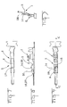
- Figure 1 is a perspective view of a pin contact having a connecting part, a locking part and a connector tongue, a locking spring is exploded from the locking part.
- Figure 2 is a perspective representation obliquely from the rear of the pin contact of Figure 1, the locking spring is exploded from the locking part.
- Figure 3 is a perspective representation obliquely from the rear and above of the pin contact of Figure 1, with the locking spring mounted in the locking part.
- Figure 4 is a longitudinal section through the locking part of the pin contact of Figure 1, with the locking spring mounted thereon.
- Figure 5 shows a cross section of the locking part taken along line D-D of Figure 4.
- Figure 6 shows a cross section of the locking part taken along line E-E of Figure 4.
- Figure 7 is a bottom view of the pin contact of Figure 1.
- Figure 8 is a side view of the pin contact of Figure 1, with the locking spring mounted thereon.
- Figure 9 is a top view of the pin contact of Figure 1, with the locking spring mounted thereon.
- Figure 10 is a view of two stamped blanks for the pin contact of Figure 1.
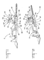
- Figure 11 is a perspective view of a second embodiment of a pin contact having the connecting part, a second locking part and the connector tongue, a second locking spring is exploded from the second locking part.
- Figure 12 is a perspective representation obliquely from the rear of the second pin contact of Figure 11, the second locking spring is exploded from the second locking part.
- Figure 13 is a perspective representation obliquely from the rear and above of the second pin contact of Figure 11, with the second locking spring mounted in the second locking part.
- Figure 14 is a longitudinal section through the second locking part of the second pin contact of Figure 11, with the second locking spring mounted thereon.
- Figure 15 shows a cross of the second locking part taken along line D-D of Figure 14.
- Figure 16 shows a cross section of the second locking part taken along line E-E of Figure 14.
- Figure 17 is a bottom view of the second pin contact of Figure 11.
- Figure 18 is a side view of the second pin contact of Figure 11, with the second locking spring mounted thereon.
- Figure 19 is a top view of the second pin contact of Figure 11, with the second locking spring mounted thereon.
- Figure 20 is a view of two stamped blanks for the second pin contact of Figure 11.
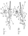
- Figure 21 is a perspective view of a third embodiment of a pin contact having the connecting part, a third locking part and the connector tongue, third locking spring is exploded from the third locking part.
- Figure 22 is a perspective representation obliquely from the rear of the third pin contact of Figure 21, the third locking spring is exploded from the third locking part.
- Figure 23 is a perspective representation obliquely from the rear and above of the third pin contact of Figure 21, with the third locking spring mounted in the second locking part.
- Figure 24 is a longitudinal section through the third locking part of the third pin contact of Figure 21, with the third locking spring mounted thereon.
- Figure 25 shows a cross section of the third locking part taken along line D-D of Figure 24.
- Figure 26 shows a cross of the third locking part, taken along line E-E of Figure 24.
- Figure 27 is a bottom view of the third pin contact of Figure 21.
- Figure 28 is a side view of the third pin contact of Figure 21, with the third locking spring mounted thereon.
- Figure 29 is a top view of the third pin contact of Figure 21, with the third locking spring mounted thereon.
- Figure 30 is a view of two stamped blanks for the third pin contact of Figure 21.
- Figures 1 and 2 are perspective views of a pin contact 1. The pin contact 1 serves to connect electrical conductors, not shown. As best shown in Figures 1 and 2, pin contact 1 has a connecting
part 2, a lockingpart 3 and a contact part constructed as aconnector tongue 4. Theconnector tongue 4 and the lockingpart 3 are plugged into a mating counterpart (not shown), in order to produce the desired electrical connection. - A stripped electrical conductor (not shown) is attached in the area of the connecting
part 2. In the present example, crimping claws 5 are used for this purpose. However, a soldered connection or a plug part or the like may be used instead. - While the connecting
part 2 is open at the top prior to closure of the crimping claws 5, theadjacent locking part 3 exhibits a closed, rectangular box section. Afirst side wall 7 and asecond side wall 8 are folded upwards at right angles from abase 6. A top 9 is folded horizontally from thefirst side wall 7 and is butt-welded to thesecond side wall 8. Thebase 6, theside walls part 3. - One
half connector tongue 4 is connected with each of thebase 6 and the top 9. Thehalves halves connector tongue 4 promotes the rigidity thereof. Thetips 12, 12' of thehalves - Above the locking
part 3 of Figures 1 and 2 there is illustrated a lockingspring 14. The lockingspring 14 is shown above the lockingpart 3 for ease of explanation. The lockingspring 14 is oriented as if it were mounted in the lockingpart 3. - A rectangular
first opening 15 is provided in thetop 9 of lockingpart 3, through which thelocking spring 14 is perpendicularly inserted. In thesecond side wall 8 there is provided a rectangular side opening 16 with anupper side 30, which serves to latch in the locking spring 14 (see also Figs. 6 and 8). Anextension 28 of thesecond side wall 8 projecting above the top 9 serves in angular orientation of the pin contact 1 in a counterpart and in protecting the lockingspring 14. In thebase 6 there is arranged a perforation pocket 17 (Figs. 4, 5, 6, 7), which is used to fix the lockingspring 14 in the longitudinal direction of the lockingpart 3. - In the area of a
rear end 18 of the lockingspring 14 there is arranged, on each side thereof, afirst guide surface 19, 19' folded at right angles. At the lower edge of thefirst guide surface 19 there is provided achannel 20, which, when the lockingspring 14 is in the installed position, extends parallel to the top 9 and lies against theinner surface 21 thereof. Therear end 18 of the lockingspring 14 is thus latched in the lockingpart 3. The front edges 22, 22' of the first guide surfaces 19, 19' extend perpendicularly to the top 9, whereby the length of thefirst opening 15 is kept as small as possible. - In the area of the
front end 23 of the lockingspring 14, an obtuse-angled first foldedportion 24 and an obtuse-angled second foldedportion 25 are provided. On each side of the obtuse-angled first foldedportion 24 there is located asecond guide surface 26, 26' folded inwards at right angles and havingupper corners 27, 27' bent outwards slightly. These engage in the lockingpart 3 after mounting of the lockingspring 14 and come to lie against theinner surface 21 of the top 9 or against theupper side 30 of theside opening 16 in thesecond side wall 8. In this way, thefront end 23 of the lockingspring 14 is also latched in the lockingpart 3. When the lockingspring 14 is subject to tensile load, the latching connection is reinforced by spreading of the bentupper corners 27, 27'. - Figure 3 shows a perspective representation, obliquely from the rear and above, of the pin contact 1 with an open connecting
part 2 and the lockingspring 14 mounted in the lockingpart 3. The protective function of theextension 28 in relation to the lockingspring 14 is clear to see. The same applies to thesecond pin contact 32 in Figure 13 and thethird pin contact 56 in Figure 23. - Figure 4 shows a cross section through the locking
part 3 with the lockingspring 14 latched or mounted therein. It reveals the top 9 with thefirst opening 15 for insertion of the lockingspring 14 and thebase 6 with theperforation pocket 17 as axial limit stop therefor in the direction of the connectingpart 2. In the opposite direction, the lockingspring 14 rests with its obtuse-angled first foldedportion 24 against thenarrow side 29 of thefirst opening 15. - In addition, Figure 4 also reveals the
channel 20 of thefirst guide surface 19, which lies against the inside 21 of the top 9, and thesecond guide surface 26, which rests against theupper side 30 of theside opening 16. - Figure 5 shows the
first side wall 7, thesecond side wall 8 with theextension 28, thebase 6 and the top 9. Furthermore, thefirst guide surface 19 is shown, with thechannel 20, which, like theupper corner 27, lies against theinner surface 21 of the top 9. Theperforation pocket 17 in thebase 6 is also visible. - Referring to Figure 6, upper corner 27' is positioned in the
side window 16 ofside wall 8. As shown, the upper corner 27' engages theupper surface 30 of theside window 16. Here too, theperforation pocket 17 may be seen. Also visible is the point where theupper corner 27 lies against theinner surface 21 of the top 9. It is also plain that thecorners 27, 27' are spread further when the lockingspring 14 is subjected to tensile loading and thereby reinforce the latching connection. Similarly, the protective action of theextension 28 relative to therear end 18 of the lockingspring 14 is visible. - Figure 7 is a bottom view of the pin contact 1 showing the
base 6 of the lockingpart 3 having theperforation pocket 17 arranged thereon. As previously described, thepocket 17 cooperates with the lockingspring 14 to limit the axial movement of the lockingspring 14. - Referring to Figure 8, the
second side wall 8 of the lockingpart 3 is provided with theside opening 16, theupper side 30 of which engages the upper corner 27'. Theend 18 of the lockingspring 14 projects only slightly beyond the extension, so that the lockingspring 14 is protected, as previously described. - As illustrated in Figure 9, the
first opening 15 of thetop 9 of the lockingpart 3 is confirmed to have the lockingspring 14 installed therein. The lockingspring 14 engages thenarrow side 29 of thefirst opening 15 thereby allowing the locking spring to pivot or swivel as necessary. - Two stamped or punched blanks for the pin contact 1 are shown in Figure 10. The blanks are connected by a conveying
strip 31 and constitute part of a reelable strip of blanks. The part of the blank strip from which thelocking part 3 is formed displays thefirst opening 15, theside opening 16 and theperforation pocket 17. - The connecting
part 2 and thehalves connector tongue 4 are integrally attached to the lockingpart 3. At thetip 12 of theupper half 10 of theconnector tongue 4 there may be seen agroove 13 and at the tip 12' of the lower half 11 a mating tongue 13', which may be clamped together during assembly of the pin contact 1 and optionally secured by welding. The conveyingstrip 31 is removed when the connectingpart 2 is fitted with a cable. - Figures 11 and 12 are perspective views of a second embodiment of the
pin contact 32. The lockingpart 33 and lockingspring 34 of thepin contact 32 differ from the lockingpart 3 and lockingspring 14 of the pin contact 1 of Figures 1 and 2. Like the lockingpart 3, thesecond locking part 33 has a rectangular cross section, with a top 35, abase 36, afirst side wall 37 and asecond side wall 38. - A first
top opening 39, a secondtop opening 40 and a thirdtop opening 41 are provided in the top 35, the openings are dimensioned to receive the lockingspring 34 therein. Anextension 42, here of divided construction, is used for angular orientation of thepin contact 32 and for protection of the lockingspring 34. - In the area of a
rear end 43 of the lockingspring 34, there is arranged on each side thereof afirst guide surface 44, 44' folded at right angles. At the rear edge of the first guide surface 44' there is provided ahook 45, which, when the lockingspring 34 is in the installed position, extends parallel to the top 35 and lies against theinner surface 46 thereof (see also Figure 14). In this way, therear end 43 of the lockingspring 34 is latched in the lockingpart 33. - In the area of the
front end 47 of the lockingspring 34, an obtuse-angled first foldedportion 48, a right-angled second foldedportion 49 and an obtuse-angled third foldedportion 50 are provided. The transition between the first, second and third folded portions is preferably radial. The second foldedportion 49 is preferably U-shaped, wherein the U shape exhibits a fixed radius of curvature. In the obtuse-angled third foldedportion 50 there is arranged afirst perforation tongue 51 directed towards the connectingpart 2. Thetongue 51 lies against theinner surface 46 of the top 35 of the lockingpart 33 after the lockingspring 34 is latched in position. In this way, thefront end 47 of the lockingspring 34 is also latched in the lockingpart 33 and the lockingspring 34 is thus secured against unwanted removal. The latching connection is reinforced by spreading of theperforation tongue 51 upon tensile loading of the lockingspring 34. - As shown in Figure 14, second and
third perforation tongues base 36 and are each bent up and inward by 90º lengthwise but in opposite directions. The tongues to fix the lockingspring 34 in the longitudinal direction. The obtuse-angled first and third foldedportions third perforation tongues web 54 in the base 36 (see Figure 17) between the second andthird perforation tongues spring 34. The right-angled second foldedportion 49 of the lockingspring 34 has an opening 55 (see also Figures 11 and 12) which mates with theweb 54. - Figure 15 shows the
second side wall 38 with theextension 42, thefirst side wall 37, the top 35 with theinner surface 46 and the base 36 with thesecond perforation tongue 52. The components of the lockingspring 34 which are visible are the first guide surfaces 44, 44' and the obtuse-angled third foldedportion 50 with thefirst perforation tongue 51. The latter lies against theinner surface 46 of the top 35 when the lockingspring 34 is in the mounted state. - Figure 16 shows the third obtuse-angled folded
portion 50 with thefirst perforation tongue 51 and the base 36 with theweb 54. - Figure 18 shows a side view of the
different locking part 33 with thesecond side wall 38 and theextension 42 thereof, which serve in orienting thepin contact 32 and in protecting the lockingspring 33. The first guide surface 44' thereof is likewise illustrated. - Figure 19 shows a top view of the
pin contact 32, with the lockingspring 34, which engages in the first, second and thirdtop openings different locking part 33. - Two stamped or punched blanks for the
pin contact 32 are shown in Figure 20. The figure shows the second andthird perforation tongues top openings - Figures 21 and 22 show a
third pin contact 56, again in perspective positions. It differs from the pin contact 1 and thesecond pin contact 32 by a modified third lockingpart 57 and a modifiedthird locking spring 58. - The locking
part 57 again exhibits a rectangular cross section, with a top 59, abase 60, afirst side wall 61 and asecond side wall 62 with anextension 78. - A first
top opening 63 and a secondtop opening 64 are provided in the top 59, which openings are dimensioned to receive the lockingspring 58. - In the area of a
rear end 65 of the lockingspring 58, there is provided on each side thereof afirst guide surface 66, 66' folded at right angles. At the rear surface of thefirst guide surface 66 there is arranged aperforation pocket 67, theedge 68 of which lies against aninner surface 69 of the top 59 after mounting of the locking spring 58 (see also Figure 24). In this way, therear end 65 of the lockingspring 58 is latched in the lockingpart 57. - In the area of a
front end 70 of the lockingspring 58, an obtuse-angled first foldedportion 71, a further right-angled second folded portion 72 (see Figure 24) and a further obtuse-angled third foldedportion 73 are provided. - Two guide surfaces 74, 74' are folded back on both sides of the obtuse-angled first folded
portion 71, these being inwardly directed, parallel and rectangular. They project downwards beyond the right-angled, second foldedportion 72 and engage, when the lockingspring 58 is in the mounted state, in first andsecond base openings top opening 63 and serve to fix the lockingspring 58 in the longitudinal direction. - Figure 24 illustrates that, after mounting of the locking
spring 58, thefree end 77 of the obtuse-angled third foldedportion 73 latches in beneath the top 59 and lies against theinner surface 69 thereof, while the right-angled second foldedportion 72 lies against thebase 60. In this way, vertical fixing of the lockingspring 58 is ensured and unwanted removal is prevented. - As is shown in Figure 25 and Figure 26, the
edge 68 of theperforation pocket 67 of thefirst guide surface 66 and thefree end 77 of the obtuse-angled third foldedportion 73 lie against theinner surface 69 of the top 59 when the lockingspring 58 is in the mounted state and thereby effect latching thereof in the lockingpart 57. - Figure 26 also shows the second guide surfaces 74, 74', which engage in the first and
second base openings base 60 and in the firsttop opening 63 of the top 59. - The bottom view of Figure 27 shows the first and
second base openings base 60 of the lockingpart 57. - The side view of Figure 28 shows the
second side wall 62 with theextension 78 and the second base opening 76 in the lockingpart 57 together with the lockingspring 58, which is extensively hidden by theprotective extension 78. - The plan view of Figure 29 shows the locking
part 57 with the lockingspring 58 and the indicated obtuse-angled first foldedportion 71 thereof together with the first guide surfaces 66, 66'. - The punched blanks for the
pin contact 56 illustrated in Figure 30 show the lockingpart 57 with the first andsecond base openings top openings - In conclusion it may be stated that the
pin contacts
Claims (8)
- An electrical pin contact (1,32,56) having a connecting part (2) and a connector tongue (4) together with a locking part (3,33,57) comprising a separate locking spring (14,34,58) for insertion into the locking part (3,33,57) perpendicularly to the longitudinal axis of the contact (1,32,56), characterised in that;
the locking spring (14,34,58) has latching means, which fix the locking spring (14,34,58) in position in the locking part (3,33,57) through insertion of the locking spring into the locking part (3,33,57), that the locking part (3,33,57) has openings (15,16,39,40,41,63,64,75,76) adapted to receive and latch the locking spring (14,34,58) in the locking part, and that the locking spring (14,34,58) has guide surfaces (19,19',26,26',44,44',66,66',74,74') and latching means at the ends (18,23,43,47,65,70) thereof. - The contact according to claim 1 characterised in that a rear guide surface (19,19',44,44',66,66'), folded at right angles, is arranged in the area of a rear end (18,43,65) of the locking spring (14,34,58) on each side thereof.
- The contact according to claim 2 characterised in that the latching means is provided at least at one of the two rear guide surfaces (19,44,66), the latching means cooperates with the openings (15,41,64) in the top (9,35,59) of the locking part (3,33,57) limits movement of the locking spring (14,34,58) and to prevent buckling thereof.
- The contact according to claim 3 characterised in that the latching means is a channel (20) on a lower edge of a rear guide surface (19).
- The contact according to claim 4 characterised in that the locking spring (14) has an obtuse-angled first folded portion (24) and an obtuse-angled second folded portion (25) in the area of its front end (23), on each side of the obtuse-angled first folded portion (24) there is arranged a second guide surface (26,26') folded inwards at right angles and having upper corners (27,27') bent slightly outwards, the upper corners (27,27') lie against an inner surface (21) of the top (9).
- The contact according to claim 4 characterised in that the locking spring (14) has an obtuse-angled first folded portion (24) and an obtuse-angled second folded portion (25) in the area of its front end (23), on each side of the obtuse-angled first folded portion (24) there is arranged a second guide surface (26,26') folded inwards at right angles and having upper corners (27,27') bent slightly outwards, the upper corners (27,27') lie against an upper side (30) of a side opening (16) in the locking part (3) after latching of the locking spring.
- The contact according to claim 4 characterised in that the locking spring (34) has an obtuse-angled first folded portion (48), a second folded portion (49) and an obtuse-angled third folded portion (50) in the area of its front end (47), a first perforation tongue (51) directed towards the connecting part (2) is provided in the obtuse-angled third folded portion (50), the perforation tongue (51) lies against the inner surface (46) of the top (35) of the different locking part (33) after latching of the locking spring (34).
- The contact according to claim 5 characterised in that the connector tongue (4) has two halves (10,11) of arched cross section each with a tip (12,12') such that the two halves (10,11) adjoin only at their edges and are latched together at their tips (12,12').
Applications Claiming Priority (2)
| Application Number | Priority Date | Filing Date | Title |
|---|---|---|---|
| DE10110628 | 2001-03-06 | ||
| DE10110628 | 2001-03-06 |
Publications (3)
| Publication Number | Publication Date |
|---|---|
| EP1239547A2 EP1239547A2 (en) | 2002-09-11 |
| EP1239547A3 EP1239547A3 (en) | 2004-08-25 |
| EP1239547B1 true EP1239547B1 (en) | 2006-06-07 |
Family
ID=7676414
Family Applications (1)
| Application Number | Title | Priority Date | Filing Date |
|---|---|---|---|
| EP02004165A Expired - Lifetime EP1239547B1 (en) | 2001-03-06 | 2002-02-26 | Electrical contact, in particular pin contact |
Country Status (5)
| Country | Link |
|---|---|
| US (1) | US6679735B2 (en) |
| EP (1) | EP1239547B1 (en) |
| JP (1) | JP2002313468A (en) |
| KR (1) | KR100799390B1 (en) |
| DE (1) | DE60211979T2 (en) |
Families Citing this family (6)
| Publication number | Priority date | Publication date | Assignee | Title |
|---|---|---|---|---|
| JP3823811B2 (en) * | 2001-11-22 | 2006-09-20 | 住友電装株式会社 | Male tab |
| WO2007006874A1 (en) * | 2005-07-06 | 2007-01-18 | Fci | Electrical contact comprising an add-on holding lug |
| DE102007008941B3 (en) * | 2007-02-21 | 2008-08-28 | Tyco Electronics Amp Gmbh | contact element |
| GB0714969D0 (en) | 2007-08-01 | 2007-09-12 | Harwin Plc | Electrical terminal |
| DE202010011858U1 (en) * | 2010-08-25 | 2010-10-28 | Ccs Cable Connector Systems Gmbh | Plug, in particular photovoltaic plug |
| FR3044172B1 (en) * | 2015-11-20 | 2019-05-17 | Aptiv Technologies Limited | FEMALE ELECTRIC CONTACT WITH LINGUET GUIDE PAD AND METHOD FOR MANUFACTURING SUCH CONTACT |
Family Cites Families (5)
| Publication number | Priority date | Publication date | Assignee | Title |
|---|---|---|---|---|
| DE8901055U1 (en) * | 1989-01-31 | 1990-06-07 | Grote & Hartmann Gmbh & Co Kg, 5600 Wuppertal | Electrical plug contact |
| EP0762551B1 (en) | 1995-09-12 | 2002-10-16 | The Whitaker Corporation | Electrical terminal with locking lance |
| JP3159073B2 (en) * | 1996-08-08 | 2001-04-23 | 住友電装株式会社 | Terminal fitting and manufacturing method thereof |
| JPH10134872A (en) * | 1996-10-16 | 1998-05-22 | Whitaker Corp:The | Electrical contacts |
| FR2790601B1 (en) * | 1999-03-01 | 2001-04-13 | Cinch Connecteurs Sa | MALE ELECTRIC CONTACT MEMBER |
-
2002
- 2002-02-26 EP EP02004165A patent/EP1239547B1/en not_active Expired - Lifetime
- 2002-02-26 DE DE60211979T patent/DE60211979T2/en not_active Expired - Lifetime
- 2002-03-04 US US10/090,962 patent/US6679735B2/en not_active Expired - Lifetime
- 2002-03-06 KR KR1020020011836A patent/KR100799390B1/en not_active Expired - Lifetime
- 2002-03-06 JP JP2002060341A patent/JP2002313468A/en active Pending
Also Published As
| Publication number | Publication date |
|---|---|
| JP2002313468A (en) | 2002-10-25 |
| KR100799390B1 (en) | 2008-01-30 |
| DE60211979T2 (en) | 2006-12-28 |
| DE60211979D1 (en) | 2006-07-20 |
| KR20020071758A (en) | 2002-09-13 |
| EP1239547A3 (en) | 2004-08-25 |
| EP1239547A2 (en) | 2002-09-11 |
| US6679735B2 (en) | 2004-01-20 |
| US20020182943A1 (en) | 2002-12-05 |
Similar Documents
| Publication | Publication Date | Title |
|---|---|---|
| US7458863B2 (en) | Terminal fitting and a connector | |
| US6095874A (en) | Single piece electrical receptacle terminal | |
| US6186840B1 (en) | Female connector for electrical connectors having a coding rib | |
| CA2286788C (en) | Connector with a terminal vibration preventing mechanism | |
| US6733346B2 (en) | Terminal fitting, a connector provided therewith and a method for forming a terminal fitting | |
| EP1689034B1 (en) | A terminal fitting, connector provided therewith and method of forming a terminal fitting | |
| EP0829925B1 (en) | Terminal locking structure | |
| US6679735B2 (en) | Electrical contact, in particular pin contact | |
| US5743771A (en) | Terminal for electrical connector | |
| EP0762551A2 (en) | Electrical terminal with locking lance | |
| EP0938758B1 (en) | Electrical contact | |
| US7357680B2 (en) | Male terminal fitting and blank therefor | |
| EP1689032B1 (en) | A terminal fitting, a plate material therefor and a method of forming it | |
| EP0959531B1 (en) | Single piece electrical receptacle terminal | |
| US5520556A (en) | Female terminal | |
| DE69804938T2 (en) | ONE-PIECE POLARIZED ELECTRICAL CONNECTING ELEMENT | |
| JP4583193B2 (en) | connector | |
| EP2654140B1 (en) | Seam closure of a receptacle contact | |
| EP1689039B1 (en) | A terminal fitting and a method of forming it | |
| JP2947080B2 (en) | Female terminal fitting of connector | |
| JP3583810B2 (en) | Connection terminal for insertion | |
| WO1998031076A2 (en) | Contact latch member and electrical connector using the same | |
| EP0969559A2 (en) | Electrical receptacle contact | |
| EP1401057A1 (en) | Electric terminal | |
| KR20000016703A (en) | Plug connector sleeve |
Legal Events
| Date | Code | Title | Description |
|---|---|---|---|
| PUAI | Public reference made under article 153(3) epc to a published international application that has entered the european phase |
Free format text: ORIGINAL CODE: 0009012 |
|
| AK | Designated contracting states |
Kind code of ref document: A2 Designated state(s): AT BE CH CY DE DK ES FI FR GB GR IE IT LI LU MC NL PT SE TR |
|
| AX | Request for extension of the european patent |
Free format text: AL;LT;LV;MK;RO;SI |
|
| PUAL | Search report despatched |
Free format text: ORIGINAL CODE: 0009013 |
|
| AK | Designated contracting states |
Kind code of ref document: A3 Designated state(s): AT BE CH CY DE DK ES FI FR GB GR IE IT LI LU MC NL PT SE TR |
|
| AX | Request for extension of the european patent |
Extension state: AL LT LV MK RO SI |
|
| RIC1 | Information provided on ipc code assigned before grant |
Ipc: 7H 01R 13/434 A Ipc: 7H 01R 13/187 B |
|
| 17P | Request for examination filed |
Effective date: 20041201 |
|
| 17Q | First examination report despatched |
Effective date: 20050317 |
|
| AKX | Designation fees paid |
Designated state(s): DE FR GB IT |
|
| GRAP | Despatch of communication of intention to grant a patent |
Free format text: ORIGINAL CODE: EPIDOSNIGR1 |
|
| GRAS | Grant fee paid |
Free format text: ORIGINAL CODE: EPIDOSNIGR3 |
|
| GRAA | (expected) grant |
Free format text: ORIGINAL CODE: 0009210 |
|
| AK | Designated contracting states |
Kind code of ref document: B1 Designated state(s): DE FR GB IT |
|
| PG25 | Lapsed in a contracting state [announced via postgrant information from national office to epo] |
Ref country code: IT Free format text: LAPSE BECAUSE OF FAILURE TO SUBMIT A TRANSLATION OF THE DESCRIPTION OR TO PAY THE FEE WITHIN THE PRESCRIBED TIME-LIMIT;WARNING: LAPSES OF ITALIAN PATENTS WITH EFFECTIVE DATE BEFORE 2007 MAY HAVE OCCURRED AT ANY TIME BEFORE 2007. THE CORRECT EFFECTIVE DATE MAY BE DIFFERENT FROM THE ONE RECORDED. Effective date: 20060607 |
|
| REG | Reference to a national code |
Ref country code: GB Ref legal event code: FG4D Free format text: NOT ENGLISH |
|
| REG | Reference to a national code |
Ref country code: GB Ref legal event code: ERR Free format text: NOTIFICATION HAS BEEN RECEIVED FROM THE EUROPEAN PATENT OFFICE THAT THE PUBLICATION LANGUAGE IS ACTUALLY ENGLISH |
|
| REF | Corresponds to: |
Ref document number: 60211979 Country of ref document: DE Date of ref document: 20060720 Kind code of ref document: P |
|
| ET | Fr: translation filed | ||
| PLBE | No opposition filed within time limit |
Free format text: ORIGINAL CODE: 0009261 |
|
| STAA | Information on the status of an ep patent application or granted ep patent |
Free format text: STATUS: NO OPPOSITION FILED WITHIN TIME LIMIT |
|
| 26N | No opposition filed |
Effective date: 20070308 |
|
| REG | Reference to a national code |
Ref country code: FR Ref legal event code: PLFP Year of fee payment: 14 |
|
| REG | Reference to a national code |
Ref country code: DE Ref legal event code: R082 Ref document number: 60211979 Country of ref document: DE Representative=s name: WILHELM & BECK, DE Ref country code: DE Ref legal event code: R081 Ref document number: 60211979 Country of ref document: DE Owner name: TE CONNECTIVITY GERMANY GMBH, DE Free format text: FORMER OWNER: TYCO ELECTRONICS AMP GMBH, 64625 BENSHEIM, DE |
|
| REG | Reference to a national code |
Ref country code: FR Ref legal event code: CD Owner name: TE CONNECTIVITY GERMANY GMBH Effective date: 20151027 |
|
| REG | Reference to a national code |
Ref country code: FR Ref legal event code: PLFP Year of fee payment: 15 |
|
| REG | Reference to a national code |
Ref country code: FR Ref legal event code: PLFP Year of fee payment: 16 |
|
| REG | Reference to a national code |
Ref country code: FR Ref legal event code: PLFP Year of fee payment: 17 |
|
| PGFP | Annual fee paid to national office [announced via postgrant information from national office to epo] |
Ref country code: PL Payment date: 20190222 Year of fee payment: 9 |
|
| GBPC | Gb: european patent ceased through non-payment of renewal fee |
Effective date: 20200226 |
|
| PG25 | Lapsed in a contracting state [announced via postgrant information from national office to epo] |
Ref country code: GB Free format text: LAPSE BECAUSE OF NON-PAYMENT OF DUE FEES Effective date: 20200226 |
|
| PGFP | Annual fee paid to national office [announced via postgrant information from national office to epo] |
Ref country code: FR Payment date: 20210112 Year of fee payment: 20 |
|
| PGFP | Annual fee paid to national office [announced via postgrant information from national office to epo] |
Ref country code: DE Payment date: 20210216 Year of fee payment: 20 |
|
| PGFP | Annual fee paid to national office [announced via postgrant information from national office to epo] |
Ref country code: IT Payment date: 20210112 Year of fee payment: 20 |
|
| REG | Reference to a national code |
Ref country code: DE Ref legal event code: R071 Ref document number: 60211979 Country of ref document: DE |