EP1239341A2 - Toner cartridge and mechanism for detecting remaining amount of toner - Google Patents
Toner cartridge and mechanism for detecting remaining amount of toner Download PDFInfo
- Publication number
- EP1239341A2 EP1239341A2 EP02004885A EP02004885A EP1239341A2 EP 1239341 A2 EP1239341 A2 EP 1239341A2 EP 02004885 A EP02004885 A EP 02004885A EP 02004885 A EP02004885 A EP 02004885A EP 1239341 A2 EP1239341 A2 EP 1239341A2
- Authority
- EP
- European Patent Office
- Prior art keywords
- toner
- agitator
- toner agitator
- damper
- dampers
- Prior art date
- Legal status (The legal status is an assumption and is not a legal conclusion. Google has not performed a legal analysis and makes no representation as to the accuracy of the status listed.)
- Granted
Links
Images







Classifications
-
- G—PHYSICS
- G03—PHOTOGRAPHY; CINEMATOGRAPHY; ANALOGOUS TECHNIQUES USING WAVES OTHER THAN OPTICAL WAVES; ELECTROGRAPHY; HOLOGRAPHY
- G03G—ELECTROGRAPHY; ELECTROPHOTOGRAPHY; MAGNETOGRAPHY
- G03G15/00—Apparatus for electrographic processes using a charge pattern
- G03G15/06—Apparatus for electrographic processes using a charge pattern for developing
- G03G15/08—Apparatus for electrographic processes using a charge pattern for developing using a solid developer, e.g. powder developer
- G03G15/0822—Arrangements for preparing, mixing, supplying or dispensing developer
- G03G15/0848—Arrangements for testing or measuring developer properties or quality, e.g. charge, size, flowability
- G03G15/0849—Detection or control means for the developer concentration
- G03G15/0855—Detection or control means for the developer concentration the concentration being measured by optical means
-
- G—PHYSICS
- G03—PHOTOGRAPHY; CINEMATOGRAPHY; ANALOGOUS TECHNIQUES USING WAVES OTHER THAN OPTICAL WAVES; ELECTROGRAPHY; HOLOGRAPHY
- G03G—ELECTROGRAPHY; ELECTROPHOTOGRAPHY; MAGNETOGRAPHY
- G03G15/00—Apparatus for electrographic processes using a charge pattern
- G03G15/06—Apparatus for electrographic processes using a charge pattern for developing
- G03G15/08—Apparatus for electrographic processes using a charge pattern for developing using a solid developer, e.g. powder developer
- G03G15/0822—Arrangements for preparing, mixing, supplying or dispensing developer
- G03G15/0848—Arrangements for testing or measuring developer properties or quality, e.g. charge, size, flowability
- G03G15/0856—Detection or control means for the developer level
-
- G—PHYSICS
- G03—PHOTOGRAPHY; CINEMATOGRAPHY; ANALOGOUS TECHNIQUES USING WAVES OTHER THAN OPTICAL WAVES; ELECTROGRAPHY; HOLOGRAPHY
- G03G—ELECTROGRAPHY; ELECTROPHOTOGRAPHY; MAGNETOGRAPHY
- G03G15/00—Apparatus for electrographic processes using a charge pattern
- G03G15/06—Apparatus for electrographic processes using a charge pattern for developing
- G03G15/08—Apparatus for electrographic processes using a charge pattern for developing using a solid developer, e.g. powder developer
- G03G15/0822—Arrangements for preparing, mixing, supplying or dispensing developer
- G03G15/0848—Arrangements for testing or measuring developer properties or quality, e.g. charge, size, flowability
- G03G15/0856—Detection or control means for the developer level
- G03G15/0858—Detection or control means for the developer level the level being measured by mechanical means
-
- G—PHYSICS
- G03—PHOTOGRAPHY; CINEMATOGRAPHY; ANALOGOUS TECHNIQUES USING WAVES OTHER THAN OPTICAL WAVES; ELECTROGRAPHY; HOLOGRAPHY
- G03G—ELECTROGRAPHY; ELECTROPHOTOGRAPHY; MAGNETOGRAPHY
- G03G15/00—Apparatus for electrographic processes using a charge pattern
- G03G15/06—Apparatus for electrographic processes using a charge pattern for developing
- G03G15/08—Apparatus for electrographic processes using a charge pattern for developing using a solid developer, e.g. powder developer
- G03G15/0822—Arrangements for preparing, mixing, supplying or dispensing developer
- G03G15/0865—Arrangements for supplying new developer
-
- G—PHYSICS
- G03—PHOTOGRAPHY; CINEMATOGRAPHY; ANALOGOUS TECHNIQUES USING WAVES OTHER THAN OPTICAL WAVES; ELECTROGRAPHY; HOLOGRAPHY
- G03G—ELECTROGRAPHY; ELECTROPHOTOGRAPHY; MAGNETOGRAPHY
- G03G15/00—Apparatus for electrographic processes using a charge pattern
- G03G15/06—Apparatus for electrographic processes using a charge pattern for developing
- G03G15/08—Apparatus for electrographic processes using a charge pattern for developing using a solid developer, e.g. powder developer
- G03G15/0822—Arrangements for preparing, mixing, supplying or dispensing developer
- G03G15/0865—Arrangements for supplying new developer
- G03G15/0867—Arrangements for supplying new developer cylindrical developer cartridges, e.g. toner bottles for the developer replenishing opening
- G03G15/087—Developer cartridges having a longitudinal rotational axis, around which at least one part is rotated when mounting or using the cartridge
- G03G15/0872—Developer cartridges having a longitudinal rotational axis, around which at least one part is rotated when mounting or using the cartridge the developer cartridges being generally horizontally mounted parallel to its longitudinal rotational axis
-
- G—PHYSICS
- G03—PHOTOGRAPHY; CINEMATOGRAPHY; ANALOGOUS TECHNIQUES USING WAVES OTHER THAN OPTICAL WAVES; ELECTROGRAPHY; HOLOGRAPHY
- G03G—ELECTROGRAPHY; ELECTROPHOTOGRAPHY; MAGNETOGRAPHY
- G03G2215/00—Apparatus for electrophotographic processes
- G03G2215/08—Details of powder developing device not concerning the development directly
- G03G2215/0802—Arrangements for agitating or circulating developer material
- G03G2215/085—Stirring member in developer container
Definitions
- the present invention relates to a toner cartridge and a mechanism for detecting remaining quantity of toner.
- Fig. 25 illustrates a conventional toner chamber and a toner agitator provided therein.
- Fig. 26 illustrates a toner chamber of a conventional toner cartridge when the toner chamber is nearly empty of toner.
- Fig. 27 illustrates the toner chamber of the conventional toner chamber when the toner chamber holds a sufficient amount of toner.
- Fig. 28 illustrates the output signal of a toner sensor indicative of the remaining toner in the toner chamber.
- a toner agitator 92 is free to rotate in a toner chamber 91.
- the toner chamber 91 has a gear, not shown, rotatably attached thereto.
- the gear 95 has a projection 94 that pushes the toner agitator 92 when the gear 95 rotates.
- the projection 94 pushes the toner agitator 92 so that the toner agitator 92 rotates together with the gear 95.
- the toner agitator 92 rotates past its highest position in the toner chamber 91, the toner agitator 92 drops due to its own weight. If the toner chamber 91 holds a sufficient amount of toner therein as shown in Fig.
- the toner agitator 92 leaves the projection 94 to land and rest on a pile of toner. If the toner chamber 91 holds little toner therein as shown in Fig. 26, when the toner agitator 92 rotates past its highest position, the toner agitator 92 drops and rotates to its lowest position due to its own weight. After the toner agitator 92 drops from its highest position, the gear 95 still continues to rotate so that the projection 94 pushes the toner agitator 92 again to rotate together with the toner agitator 92. The toner agitator 92 stays at its lowest position for a longer time period when the toner chamber 91 holds little toner therein than when the toner chamber 91 holds a sufficient amount of toner therein.
- a magnet-sensitive toner sensor is disposed outside of the toner chamber 91.
- the toner agitator 92 has a magnet attached thereto. As the toner agitator 92 rotates, the magnet passes the toner sensor. The toner sensor detects the magnetic flux of the magnet and outputs a sensor output as shown in Fig. 28.
- the toner agitator 92 when the toner agitator 92 is within an angular range ⁇ , the toner agitator 92 is substantially at its lowest position and the toner sensor outputs a signal indicative of "a toner-low.”
- the conventional toner agitator 92 suffers from a problem that the toner agitator 92 tends to oscillate back and forth about its lowest position when the toner chamber 91 holds little toner therein.
- a toner cartridge (17) includes a toner holding section (10), a toner agitator (12), a damper (14, 24, 34, 44, 47, 48, 49, 51), and a position indicator (13b).
- the toner holding section (10) is a toner chamber that holds toner therein.
- the toner agitator is disposed in the toner holding section (17) and is free to rotate.
- the toner agitator (12) is driven in rotation to agitate the toner when it is pushed to rotate.
- the damper (14, 24, 34, 44, 47, 48, 49, 51) damps the motion of the toner agitator (12) when the toner agitator (12) rotates freely, the damper being disposed in the toner holding section (17).
- the position indicator (13b) is attached to the toner agitator (12) and indicates the rotational position of the toner agitator (12).
- the damper is disposed in a path through which the toner agitator (12) rotates, the damper defining an angular range ( ⁇ ) through which the toner agitator rotates while the position indicator is detected by an external device.
- the damper is formed of a resilient film material and is bent into a base portion (14b), and a raised portion (14a, 24a, 48a, 34a, 49a).
- the base portion (14b) is fixed to an inner surface of the toner holding section (17) and the raised portion extends into the path.
- the raised portion exhibits a first resistance against a first force that causes the raised portion, to deform inwardly relative to the angular range ( ⁇ ) and a second resistance against a second force that causes the raised portion to deform outwardly relative to the angular range ( ⁇ ).
- the damper is one of two dampers (14, 24, 34, 44, 48, 49, 51).
- a first one (24, 34, 44, 48, 49, 51) of the two dampers is disposed at an upstream end of the angular range with respect to rotation of the toner agitator (12).
- a second (14) one of the two dampers is disposed at a downstream end of the angular range ( ⁇ ) with respect to rotation of the toner agitator.
- the raised portion of the second one of the two dampers lies in a plane at an angle ( ⁇ ) with a plane in which the raised portion of the first one of the two dampers lies.
- the toner agitator (12) stays in the angular range for a shorter time when the toner cartridge (17) holds a larger amount of toner therein than when the toner cartridge (17) is nearly empty of toner.
- the raised portion (44a) has a plurality of slits extending in a direction in which the raised portion extends.
- the toner agitator (12) is pushed by a drive member to rotate about a substantially horizontal axis.
- the toner agitator (12) drops from the vertical highest position due to its own weight.
- the external device detects the magnetic field.
- the position indicator (13b) is a magnet attached to the toner agitator.
- the magnet radiates a magnetic field that is detected by the external device.
- the toner agitator (12) is disposed in the toner cartridge (17) and is free to rotate about an axis.
- the toner agitator (12) is driven in rotation to agitate the toner.
- the damper damps the motion of the toner agitator (12) when the toner agitator (12) rotates freely.
- the position indicator (13b) is attached to the toner agitator (12) and transmits a signal indicative of a rotational position of the toner agitator (12).
- An external detector (15) is provided on the image-forming unit (70) and detects the signal when the toner agitator is rotated.
- the damper is disposed in a path through which the toner agitator (12) rotates, the damper damping the motion of the toner agitator when the toner agitator is within a range ( ⁇ ) of rotational angle.
- the damper is formed of a resilient film material bent into a base portion fixed to an inner surface of the toner cartridge (17) and a raised portion extending into the path.
- the damper is one of two dampers (14, 24, 34, 44, 48, 49, 51).
- a first one (24, 34, 44, 48, 49, 51) of the two dampers is disposed at an upstream end of the range ( ⁇ ) of rotational angle with respect to rotation of the toner agitator (12).
- a second one (14) of the two dampers is disposed at a downstream end of the range ( ⁇ ) of rotational angle with respect to rotation of the toner agitator (12).
- the raised portion of the first one (44) of the two dampers has a plurality of slits formed in a direction in which the raised portion of the first one of the two dampers extends.
- the second one of the two dampers is disposed such that the raised portion lies in a plane at an angle ( ⁇ ) with the axis.
- the toner agitator is rotatable freely about the axis.
- the second portion operates such that when the toner agitator rotates freely within the range ( ⁇ ) of rotational angle, the second portion repels the toner agitator to stay within the range ( ⁇ ) of rotational angle.
- the second portion operates such that when the toner agitator is rotated by the drive member, the second portion allows the toner agitator to move out of the range ( ⁇ ) of rotational angle ( ⁇ ).
- the toner agitator (12) is pushed by a drive member to rotate about a substantially horizontal axis.
- the toner agitator (12) drops from the vertical highest position due to its own weight and rotates about the substantially horizontal axis.
- the toner agitator (12) is substantially in the range ( ⁇ ) of rotational angle, the signal is detected.
- the position indicator (13b) is a magnet attached to the toner agitator and radiates a magnetic field.
- the detector (15) is a magnetoresistive element and detects the magnetic field.
- the toner agitator (12) stays within the range ( ⁇ ) of rotational angle for a shorter time when the toner cartridge (17) holds a larger amount of toner therein than when the toner cartridge (17) is nearly empty of toner.
- An image-forming unit (70) receives a toner cartridge (17) attached thereto.
- the toner cartridge (17) includes a toner agitator (12) free to rotate and a position indicator (13) that indicates a rotational position of the toner agitator (12).
- the toner agitator (12) is driven in rotation when it is pushed to rotate.
- the image-forming unit (70) includes a space that receives the toner cartridge (17) therein and a detector that detects the position indicator when the position is at a certain rotational position.
- the position indicator (13b) is a magnet that radiates a magnetic field and the detector is a magnetoresistive element that detects the magnetic field.
- the toner agitator (12) is pushed by a drive member to rotate about a substantially horizontal axis.
- the toner agitator (12) drops from the vertical highest position due to its own weight.
- the detector detects the magnetic field.
- Fig. 1 is a perspective view illustrating a pertinent portion of an image-forming apparatus according a first embodiment.
- Fig. 2 is a perspective view with a partial cross-sectional view, illustrating an image-forming unit of the image-forming apparatus and a toner cartridge according to the first embodiment.
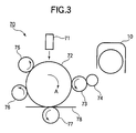
- Fig. 3 is a model representation of the image-forming unit of Fig. 6.
- an image-forming apparatus has an image-forming unit 70 and a toner cartridge 10.
- the image-forming unit 70 is mounted on a side frame 80 assembled to the image-forming apparatus.
- the image-forming unit 70 includes a rotating photoconductive drum 72 and associated rotating structural elements.
- the photoconductive drum 72 rotates in a direction shown by arrow A.
- a charging roller 75 rotates in contact with the photoconductive drum 72 to charge the surface of the photoconductive drum 72 uniformly.
- An LED head 71 illuminates the charged surface of the photoconductive drum 72 in accordance with print data to form an electrostatic latent image on the photoconductive drum 72.
- a developing roller 73 rotates in contact with the photoconductive drum 72 to develop the electrostatic latent image with toner into a toner image.
- a toner-supplying roller 74 rotates in contact with the developing roller 73 to supply the toner to the developing roller 73.
- a toner cartridge 10 is disposed above the toner-supplying roller 74 to supply toner.
- a neutralizing and cleaning roller 76 rotates in contact with the photoconductive drum 72.
- a transfer roller 77 rotates in contact with the photoconductive drum 72 with a print medium 78 sandwiched between the transfer roller 77 and the photoconductive drum 72, so that the toner image is transferred electrostatically from the photoconductive drum 72 onto the print medium 78.
- the toner cartridge 10 holds toner therein.
- the toner is discharged from a lower portion of the toner cartridge 10 and supplied to the toner-supplying roller 74.
- the toner cartridge 10 includes a toner agitator 12 in the shape of a bar or rod, which is rotated by a gear 21 (Fig. 8) driven by a driving source, not shown.
- the toner agitator 12 agitates the toner to prevent the toner from clumping, so that the toner cartridge 10 discharges uniform toner particles.
- the toner agitator 12 also serves as a part of a toner remaining indicator, which will be described later, that detects "a toner-low state" in which only a small amount of toner is left in the toner cartridge 10.
- the toner agitator 12 is in the shape of a crank shaft and has a shaft 12c, a radial portion 12b, and a bar 12a formed in one piece construction.
- the toner agitator 12 also has a short bar 13a that projects radially from the shaft 12c and has a magnet 13b attached to a tip thereof.
- the toner agitator 12 rotates about the shaft 12c in a direction shown by arrow A, so that the bar 12a describes a circular rotational path in a toner holder 17.
- the radial portion 12b and the short bar 13a are angularly spaced apart by 90 degrees such that when the bar 12a is at its lowest position, the short bar 13a extends horizontally.
- a magnet-detecting sensor 15 is attached to the side frame 80 to oppose the magnet 13b at a position where the magnet takes up when the bar 12a is at its lowest position.
- the magnet-detecting sensor 15 includes a magnetoresistive element such as Hall effect element that detects a magnetic field, and a connector that electrically connects the magnet-detecting sensor 15 and the control means, not shown, of the image-forming apparatus.
- a magnetoresistive element such as Hall effect element that detects a magnetic field
- a connector that electrically connects the magnet-detecting sensor 15 and the control means, not shown, of the image-forming apparatus.
- Fig. 4 is a perspective view with a partial cross-sectional view of the toner cartridge.
- the toner holder 17 is assembled into an outer case 16.
- the toner holder 17 has a plurality of large openings in its upper portion through which the toner flows into the toner holder 17 from the outer case 16.
- the toner holder 17 has a plurality of toner-discharging openings 18 formed in a bottom floor thereof. The toner is supplied through the toner-discharging openings 18 to the toner-supplying roller 74.
- a damper 14 is provided on the inner surface of the toner holder 17 and serves as a device that progressively diminishes oscillatory motion of the bar 12a back and forth about a location at which a magnet detecting sensor 15 is disposed.
- the damper 14 is formed of a resilient resin material such as polyester and has a base portion 14b and a raised portion 14a.
- the base portion 14a is fixed to the inner surface of the toner holder 17 by, for example, an adhesive, the raised portion 14a extends into the path of the toner agitator and substantially traverses the circular rotational path of the bar 12a.
- the damper 14 is disposed so that the raised portion 14a is on the right end of an angular range ⁇ of Fig. 5, i.e., the raised portion 14a is at a downstream end of the angular range ( ⁇ ) with respect to rotation of the toner agitator.
- the photoconductive drum 72 (Fig. 2) is driven by a drive source, not shown, such as a motor to rotate clockwise. Then, the LED head 71 illuminates the surface of the photoconductive drum 72, charged by the charging roller 75, to form an electrostatic latent image. As the photoconductive drum 72 rotates, the electrostatic latent image is developed with toner by the developing roller 73 into a toner image.
- the toner image is then transferred onto the print medium 78, advanced on a carrier belt, not shown, into a transfer point defined between the photoconductive drum 72 and the transfer roller 77.
- the print medium 78 is advanced to a fixing unit, not shown, where the toner image is fused into the print medium 78 into a permanent image. Then, the print medium 78 is discharged from the image-forming apparatus.
- the cleaning roller 76 charges the surface of the photoconductive drum 72 on which the toner image was formed so that the surface is subjected to an electric field of a polarity opposite to that of the residual toner particles on the photoconductive drum 72.
- the cleaning roller 76 removes the residual toner particles on the photoconductive drum 72 and neutralizes the surface of the photoconductive drum 72. Thereafter, the surface of the photoconductive drum 72 is charged again uniformly by the charging roller 75.
- the photoconductive drum 72 further continues to rotate to repeat the aforementioned steps of electrophotography.
- Fig. 5 is a cross-sectional view of the toner cartridge.
- Fig. 6 illustrates the function of the damper of the invention.
- Fig. 7 is a perspective view with a partial cross-sectional view of the toner cartridge.
- the bar 12a of the toner agitator 12 rotates to its lowest position, it takes up a position as shown in Fig. 4.
- the bar 12a of the toner agitator 12 rotates to its highest position, it takes up a position as shown in Fig. 7.
- the magnet detecting sensor 15 detects the magnet 13a.
- Fig. 8 illustrates a mechanism that causes the toner agitator to rotate.
- Fig. 9A illustrates the positional relation between the gear and the toner agitator when the toner cartridge 10 holds a sufficient amount of toner.
- the projection 20 pushes the bar 12 to rotates together with the bar 12 until the bar 12a rotates past its highest position in the toner holder 17.
- the bar 12a drops suddenly from its highest position due to its own weight but lands and rests on the pile of toner.
- the bar 12a is outside of the angular range ⁇ and therefore the magnet-detecting sensor 15 does not generate an output.
- the projection 20 again abuts the radial portion 12b of the toner agitator 12 and pushes it to rotate together with the gear 20, thereby agitating the toner.
- the bar 12a passes through the angular range ⁇ at the same speed as the gear, i.e., a fairly high speed. Therefore, the output of the magnet-detecting sensor 15 is of a short duration and does not indicate the "toner-low state.”
- Fig. 9B illustrates the positional relation between the gear and the toner agitator when the toner cartridge 10 is almost empty of toner.
- the projection 20 pushes the bar 12 to rotates together with the bar 12 until the bar 12a rotates past its highest position in the toner holder 17.
- the bar 12a drops suddenly from its highest position due to its own weight to its substantially lowest position.
- the bar 12a that has dropped from its highest position does not receive very much resistance of toner and therefore travels through the angular range at a high speed. However, the bar 12a collides against the raised portion 14a of the damper 14.
- the raised portion 14a is disposed on the right side end of the angular range ⁇ of Fig. 6.
- the damper 14 has a certain rigidity and resiliency such that the bar 12a cannot overcome the raised portion 14a but is repelled.
- the bar 12a stays within the angular range ⁇ until it is pushed by the projection 20 of the gear 21.
- the bar 12a stays within the angular range ⁇ for a longer time period when the toner cartridge 10 is nearly empty of toner than when the toner cartridge 10 holds a large amount of toner therein.
- the output of the toner-detecting sensor 15 indicates the toner-low state.
- the raised portion 14a of the damper 14 has rigidity such that the raised portion 14a repels the bar 12a but yieldingly flex to allow the bar 12a to overcome the raised portion 14a when the projection 20 of the gear 21 pushes the radial portion 12b.
- Fig. 10 is a cross-sectional view of a toner cartridge according to a second embodiment.
- Fig. 11 is a perspective view with a partial cross-sectional view of the toner cartridge of Fig. 10.
- damper 24 is attached to an inner bottom surface of the toner holder 17.
- Abase portion 24b is fixed to the inner bottom surface of the toner holder 17 by an adhesive.
- the damper 24 is formed of the same material as the damper 14 and is of the same structure as the damper 14.
- the damper 24 is positioned such that a raised portion 24a is at the left end of the angular range ⁇ .
- the raised portion 24a and raised portion 14a are symmetric with respect to a vertical line passing through the shaft 12c such that the flat surface of the raised portion 14a opposes and is substantially parallel to the flat surface of the raised portion 24a.
- the raised portion 24a is disposed at an upstream end of the angular range ⁇ with respect to rotation of the toner agitator and the raised portion 14a is disposed at a downstream end of the range ⁇ with respect to rotation of the toner agitator.
- Fig. 12 illustrates the operation of the dampers 14 and 24.
- Fig. 13 illustrates the operation of the damper 24.
- Fig. 14 illustrates the operation of the damper 14.
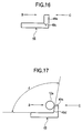
- Figs. 15, 16, and 17 show the modification of the damper 24.
- the bar 12a that has dropped due to its own weight collides against the raised portion 24a.
- the raised portion 24a yieldingly flexes so that the bar 12a overrides the raised portion 24a to move past the raised portion 24a toward the raised portion 14a of the damper 14.
- the bar 12a is then repelled by the raised portion 14a in a direction shown by arrow C to collide against the raised portion 24a.
- the impact exerted on the raised portion 24a by the bar 12a is weak and therefore the raised portion 24a does not yieldingly flex but repels the bar 12a.
- the bar 12a stays within the angular range ⁇ so that the output of the toner-detecting sensor 15 is of a long duration (Fig. 2) that indicates the toner-low state.
- the dampers 14 and 24 are formed of a resin material such as polyester.
- the raised portion 24a exhibits less rigidity when the bar 12a collides against the raised portion 24a in such a direction as to open the damper (Fig. 13) than when the bar 12a collides against the raised portion 24a in such a direction as to fold the damper (Fig. 14).
- the dampers 14 and 24 are positioned relative to each other such that when the bar 12a collides against the raised portion 24a, the distance X between the raised portion 24a and the raised portion 14a is much larger than the diameter of the bar 12a.
- the raised portion 24a quickly regains its original position shortly after it flexes yieldingly. Therefore, when the bar 12a swings in the C direction of Fig. 12, the bar 12a does not override the raised portion 24a.
- a damper 47 may be formed such that the angle ⁇ between the raised portion 47a and the base portion 47b is larger than 90 degrees as shown in Fig. 15.
- a damper 49 may be cut partly in a portion about which the damper 49 is bent into a raised portion 49d and a base portion 49a to make an angle of about 90 degrees.
- the damper 49 has smaller rigidity when the bar 12a collides against the damper 49 in the B direction and larger rigidity when the bar 12a collides against the damper 49 in the C direction.
- the damper 49 is difficult to be overridden by the bar 12a when the bar 12a collides against the damper 49 in the C direction.
- the damper 49 may be formed such that the raised portion 49a of the damper 49 is tapered and the raised portion 49a makes an angle ⁇ larger than 90 degrees with the base portion 49b.
- the damper 49 has a small rigidity when the bar 12a collides against the damper 49 in the B direction and a large rigidity when the bar 12a collides against the damper 49 in the C direction.
- the damper 14 may also be modified in the same way as shown Figs. 15 to 17.
- Fig. 18 is a perspective view with a partial cross-sectional view, illustrating a toner cartridge according to a third embodiment.
- Fig. 19 illustrates dampers as seen from above according to the third embodiment.
- a damper 34 is positioned as shown in Fig. 19 such that the flat surface of the raised portion 34a lies in a plane at an angle ⁇ with a plane in which the raised portion 14a lies or a vertical plane passing through the shaft 12c.
- the dampers 14 and 34 are positioned relative to each other such that when the bar 12a collides against the raised portion 24a, the distance X between the raised portion 34a and the raised portion 14a is much longer than the diameter of the bar 12a. It is ensured that the distance X is within the angular range ⁇ of Fig. 10.
- the bar 12a first swings in the B direction to collide against the raised portion 34a at a corner portion 34b and then progressively across entire raised portion 34a.
- the rigidity is small and gradually increases as the bar 12a collides against the entire raised portion 34a.
- the bar 12a has a small kinetic energy when it collides against the corner portion 34b, the bar 12a is not repelled by the raised portion 34b but overrides the raised portion 34b into the angular range ⁇ , so that the toner-low state is reliably detected.
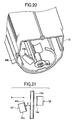
- Fig. 20 is a perspective view with a partial cross-sectional view of a toner cartridge according to a fourth embodiment.
- Fig. 21 illustrates dampers according to the fourth embodiment.
- Fig. 22 is a perspective view of the damper.
- a damper 44 includes a raised portion 44a and a base portion 44b.
- the damper 44 is positioned as shown in Fig. 21 such that the flat surface of the raised portion 44a lies in a plane at an angle ⁇ with a plane in which the raised portion 14a lies or a vertical plane passing through the shaft 12c.
- the raised portion 44a is separated by slits into a plurality of fingers f1 to fn.
- the fingers have widths b1, b2, b3, ⁇ bn, which may be the same or different.
- the bar 12a collides against a corner portion 44b of the raised portion 44a and then swings further overriding the fingers progressively toward the damper 14.
- the bar 12a receives progressively large repelling force b1, b1+b2, b1+b2+b3, b1+b2+b3+b4, ⁇ , b1+b2+ ⁇ +bn.
- the bar 12a has a small kinetic energy when it collides against the corner portion 44b, the bar 12a is not repelled by the corner portion 44b but overrides the corner portion 44b toward the raised portion 14. The bar 12a then collides against the damper 14 and is repelled back toward the raised portion 44a. The raised portion 44a repels the bar 12a, so that the bar 12a can be within the angular range of Fig. 10. In this manner, the toner-low state is reliably detected.
- the dampers are formed of a resin material such as polyester and are attached to the inner surface of the toner holder 17 by an adhesive.
- the dampers may be of any type of retarding element, provided that when the bar 12a swings to collide against the corner portion 44b, the rotation of the toner agitator 12 is retarded.
- Figs. 23A and 23B are side views, illustrating a modification of the damper.
- Fig. 24 is a cross-sectional side view, illustrating another modification of the damper.
- a retarding member 51 is a flat spring formed of a flexible metal material element.
- the retarding member 51 is mounted on the inner surface of the toner holder 17. As shown in Figs. 23A and 23B, when the bar 12a collides against a folded portion of the retarding member 51, the bar 12a causes the retarding member 51 to be deformed into a flatter shape. The deformation of the retarding member 51 absorbs the kinetic energy when the bar 12a collides against the retarding member 51.
- projections 63 and 64 may be formed on the inner surface of the toner holder 17 so that theprojectiosn63 and 64 serve as a retarding member.
- the radial portion 12b of the toner agitator 12 has a film-like element that collides against the projections 63 and 64, thereby being retarded in swinging motion.
Landscapes
- Physics & Mathematics (AREA)
- General Physics & Mathematics (AREA)
- Dry Development In Electrophotography (AREA)
Abstract
Description
Claims (22)
- A toner cartridge comprising:a toner holding section (10), holding toner therein;a toner agitator (12) disposed in said toner holding section (10), said toner agitator (12) being free to rotate, said toner agitator (12) being driven in rotation to agitate the toner when it is pushed to rotate;a damper (14, 24, 34, 44, 47, 48, 49, 51), damping motion of said toner agitator (12) when said toner agitator (12) rotates freely, said damper being disposed in said toner holding section (10); anda position indicator attached to said toner agitator and indicating a rotational position of said toner agitator.
- The toner cartridge according to Claim 1, wherein said damper is disposed in a path through which said toner agitator (12) rotates, said damper defining an angular range (α) through which said toner agitator (12) rotates while said position indicator is detected by an external device.
- The toner cartridge according to Claim 2, wherein said damper is formed of a resilient film material and is bent into a first portion and a second portion (14a, 24a, 34a, 44a, 47a, 48a, 49a);
wherein the first portion is fixed to an inner surface of said toner holding section (10) and the second portion extends into the path. - The toner cartridge according to Claim 3, wherein the second portion exhibits a first resistance against a first force that causes the second portion to deform inwardly relative to the angular range (α) and a second resistance against a second force that causes the second portion to deform outwardly relative to the angular range (α).
- The toner cartridge according to Claim 3, wherein said damper is one of two dampers;
wherein a first one of the two dampers (14+24, 14+34, 14+44, 14+47, 14+48, 14+49) is disposed at an upstream end of the angular range (α) with respect to rotation of said toner agitator (12) and a second one of the two dampers is disposed at a downstream end of the angular range (α) with respect to rotation of said toner agitator, the second portion of the second one of the two dampers lying in a plane at an angle (β) with a plane in which the second portion of the first one of the two dampers lies. - The toner cartridge according to Claim 2, wherein said toner agitator stays in the angular range (α) for a shorter time when said toner cartridge holds a larger amount of toner therein than when said toner cartridge is nearly empty of toner.
- The toner cartridge according to Claim 3, wherein said second portion has a plurality of slits extending in a direction in which the second portion extends.
- The toner cartridge according to Claim 7, wherein said toner agitator (12) is pushed by a drive member to rotate about a substantially horizontal axis;
wherein when said toner agitator (12) is rotated past its vertical highest position, said toner agitator (12) drops from the vertical highest position due to its own weight;
wherein when said toner agitator (12) is substantially in the angular range (α), the external device detects the magnetic field. - The toner cartridge according to Claim 7, wherein said position indicator is a magnet (13b) attached to said toner agitator (12), the magnet (13b) radiating a magnetic field that is detected by the external device.
- A toner remaining detector for detecting a remaining amount of toner in a toner chamber, the detector comprising:a toner agitator disposed in the toner chamber, the toner agitator being rotated about an axis to agitate the toner;a position indicator attached to said toner agitator and transmitting a signal indicating a rotational angle of said toner agitator when said toner agitator rotates, the signal being detected by an external detecting device;a damper (14, 24, 34, 44, 47, 48, 49, 51), damping motion of said toner agitator (12) when said toner agitator (12) rotates.
- The toner remaining detector according to Claim 10, wherein said damper is disposed in a path through which said toner agitator rotates, said damper damping the motion of said toner agitator when said toner agitator is within a range (α) of rotational angle.
- The toner remaining detector according to Claim 11, wherein said damper is formed of a resilient film material bent into a first portion fixed to an inner surface of the toner chamber and a second portion (14a, 24a, 34a) extending into the path.
- The toner remaining detector according to Claim 12, wherein said damper is one of two dampers;
wherein a first one of the two dampers is disposed at an upstream end of the range (α) of rotational angle with respect to rotation of said toner agitator and a second one of the two dampers is disposed at a downstream end of the range (α) of rotational angle with respect to rotation of said toner agitator. - The toner remaining detector according to Claim 12, wherein the second portion of the first one of the two dampers has a plurality of slits formed therein.
- The toner remaining detector according to Claim 12, wherein the second one of the two dampers is disposed such that the second portion lies in a plane at an angle (β) with the axis.
- The toner remaining detector according to Claim 12, wherein said toner agitator is rotatable freely about the axis;
wherein the second portion operates such that when said toner agitator rotates freely within the range (α) of rotational angle, the second portion repels said toner agitator to stay within the range (α) of rotational angle; and
wherein the second portion operates such that when said toner agitator is rotated by the drive member, the second portion allows said toner agitator to move out of the range (α) of rotational angle (α). - The toner remaining detector according to Claim 10, wherein said toner agitator is pushed by a drive member to rotate about a substantially horizontal axis;
wherein when said toner agitator is rotated past its vertical highest position, said toner agitator drops from the vertical highest position due to its own weight and rotates about the substantially horizontal axis;
wherein when said toner agitator is substantially in the range (α) of rotational angle, the signal is detected. - The toner remaining detector according to Claim 17, wherein said position indicator is a magnet attached to said toner agitator and radiates a magnetic field:
wherein the external device is a magnetoresistive element and detects the magnetic field. - The toner remaining detector according to Claim 17, wherein the toner agitator stays within the range (α) of rotational angle for a shorter time period when the toner chamber holds a larger amount of toner therein than when the toner chamber holds a smaller amount of toner therein.
- An image-forming unit to which a toner cartridge is attached, the toner cartridge including a toner agitator free to rotate and a position indicator that indicates a rotational position of the toner agitator, the toner agitator being driven in rotation when it is pushed to rotate, the image-forming unit comprising:a space that receives the toner cartridge therein; anda detector that detects the position indicator when the position is at a certain rotational position.
- The image-forming unit according to Claim 20, wherein the position indicator is a magnet that radiates a magnetic field and said detector is a magnetoresistive element that detects the magnetic field.
- The image-forming unit according to Claim 21, wherein the toner agitator is pushed by a drive member to rotate about a substantially horizontal axis;
wherein when the toner agitator is rotated past its vertical highest position, the toner agitator drops from the vertical highest position due to its own weight;
wherein when the toner agitator is substantially in the range (α) of rotational angle, the detector detects the magnetic field.
Applications Claiming Priority (2)
| Application Number | Priority Date | Filing Date | Title |
|---|---|---|---|
| JP2001066650 | 2001-03-09 | ||
| JP2001066650A JP3825268B2 (en) | 2001-03-09 | 2001-03-09 | Toner cartridge and toner remaining amount detection mechanism |
Publications (3)
| Publication Number | Publication Date |
|---|---|
| EP1239341A2 true EP1239341A2 (en) | 2002-09-11 |
| EP1239341A3 EP1239341A3 (en) | 2004-03-17 |
| EP1239341B1 EP1239341B1 (en) | 2006-06-14 |
Family
ID=18925112
Family Applications (1)
| Application Number | Title | Priority Date | Filing Date |
|---|---|---|---|
| EP02004885A Expired - Lifetime EP1239341B1 (en) | 2001-03-09 | 2002-03-04 | Toner cartridge |
Country Status (4)
| Country | Link |
|---|---|
| US (1) | US6654569B2 (en) |
| EP (1) | EP1239341B1 (en) |
| JP (1) | JP3825268B2 (en) |
| DE (1) | DE60212226T2 (en) |
Families Citing this family (33)
| Publication number | Priority date | Publication date | Assignee | Title |
|---|---|---|---|---|
| US7136608B2 (en) * | 2003-12-19 | 2006-11-14 | Steven Miller | Removable toner cartridge universal adapter |
| US7260346B2 (en) * | 2004-05-24 | 2007-08-21 | Himes William D | Developer cartridge with a geometry configured to open and close a shutter |
| USD537110S1 (en) * | 2004-07-01 | 2007-02-20 | Seiko Epson Corporation | Photoconductor cartridge |
| US7319828B2 (en) * | 2004-07-14 | 2008-01-15 | Sharp Kabushiki Kaisha | Developing agent detecting mechanism section of developing apparatus |
| US7231153B2 (en) * | 2005-01-13 | 2007-06-12 | Xerox Corporation | Systems and methods for monitoring replaceable units |
| US7245860B2 (en) * | 2005-03-25 | 2007-07-17 | General Plastic Industrial Co., Ltd. | Toner cartridge |
| US7248806B2 (en) * | 2005-05-11 | 2007-07-24 | Lexmark International, Inc. | Paddle positioning system |
| US7076180B1 (en) * | 2005-05-24 | 2006-07-11 | General Plastic Industrial Co., Ltd. | Toner cartridge |
| JP2007298543A (en) * | 2006-04-27 | 2007-11-15 | Fuji Xerox Co Ltd | Toner cartridge |
| JP4935277B2 (en) * | 2006-09-28 | 2012-05-23 | ブラザー工業株式会社 | Image forming apparatus |
| JP5347332B2 (en) * | 2008-04-15 | 2013-11-20 | 株式会社リコー | Image forming apparatus |
| CN101907850A (en) * | 2009-06-05 | 2010-12-08 | 株式会社东芝 | Toner cartridge and image forming device |
| JP5292429B2 (en) | 2011-03-22 | 2013-09-18 | 京セラドキュメントソリューションズ株式会社 | Image forming apparatus |
| WO2012137972A1 (en) * | 2011-04-06 | 2012-10-11 | Canon Kabushiki Kaisha | Image forming apparatus |
| JP5983042B2 (en) * | 2012-05-30 | 2016-08-31 | ブラザー工業株式会社 | Development device |
| US9031424B2 (en) | 2012-12-18 | 2015-05-12 | Lexmark International, Inc. | Systems and methods for measuring a particulate material |
| US9152080B2 (en) * | 2012-12-18 | 2015-10-06 | Lexmark International, Inc. | Replaceable unit for an image forming device having a toner agitator that includes a magnet for rotational sensing |
| US9069286B2 (en) | 2012-12-18 | 2015-06-30 | Lexmark International, Inc. | Rotational sensing for a replaceable unit of an image forming device |
| US9104134B2 (en) | 2012-12-18 | 2015-08-11 | Lexmark International, Inc. | Toner level sensing for replaceable unit of an image forming device |
| US8989611B2 (en) | 2012-12-18 | 2015-03-24 | Lexmark International, Inc. | Replaceable unit for an image forming device having a falling paddle for toner level sensing |
| US9128443B2 (en) | 2012-12-18 | 2015-09-08 | Lexmark International, Inc. | Toner level sensing for replaceable unit of an image forming device |
| SG11201607362WA (en) * | 2014-03-27 | 2016-10-28 | Lexmark Int Inc | Toner level sensing for a replaceable unit of an image forming device |
| US9128444B1 (en) | 2014-04-16 | 2015-09-08 | Lexmark International, Inc. | Toner level sensing for a replaceable unit of an image forming device using pulse width patterns from a magnetic sensor |
| US9389582B2 (en) | 2014-06-02 | 2016-07-12 | Lexmark International, Inc. | Replaceable unit for an image forming device having magnets of varying angular offset for toner level sensing |
| US9519243B2 (en) | 2014-06-02 | 2016-12-13 | Lexmark International, Inc. | Replaceable unit for an image forming device having magnets of varying angular offset for toner level sensing |
| US9335656B2 (en) | 2014-06-02 | 2016-05-10 | Lexmark International, Inc. | Toner level sensing using rotatable magnets having varying angular offset |
| US9280084B1 (en) | 2015-02-25 | 2016-03-08 | Lexmark International, Inc. | Magnetic sensor positioning by a replaceable unit of an electrophotographic image forming device |
| US9291989B1 (en) | 2015-02-25 | 2016-03-22 | Lexmark International, Inc. | Replaceable unit for an electrophotographic image forming device having an engagement member for positioning a magnetic sensor |
| US10474060B1 (en) | 2018-07-05 | 2019-11-12 | Lexmark International, Inc. | Toner level sensing using rotatable magnets having varying angular offset |
| US10429765B1 (en) | 2018-07-05 | 2019-10-01 | Lexmark International, Inc. | Toner container for an image forming device having magnets of varying angular offset for toner level sensing |
| US10345736B1 (en) | 2018-07-20 | 2019-07-09 | Lexmark International, Inc. | Toner level detection measuring a radius of a rotatable magnet |
| US10451998B1 (en) | 2018-07-20 | 2019-10-22 | Lexmark International, Inc. | Toner level detection measuring an orientation of a rotatable magnet having a varying radius |
| US10451997B1 (en) | 2018-07-20 | 2019-10-22 | Lexmark International, Inc. | Toner level detection measuring an orientation of a rotatable magnet having a varying orientation relative to a pivot axis |
Family Cites Families (6)
| Publication number | Priority date | Publication date | Assignee | Title |
|---|---|---|---|---|
| JP2837973B2 (en) * | 1991-07-04 | 1998-12-16 | 沖電気工業株式会社 | Toner remaining amount detection mechanism |
| JPH06258946A (en) * | 1993-03-08 | 1994-09-16 | Matsushita Electric Ind Co Ltd | Toner level detector |
| JP3351179B2 (en) * | 1995-07-04 | 2002-11-25 | 松下電器産業株式会社 | Developing device |
| US5875378A (en) * | 1996-12-20 | 1999-02-23 | Lexmark International, Inc. | Toner cartridge with hopper exit agitator |
| JP3373139B2 (en) * | 1997-07-24 | 2003-02-04 | 株式会社沖データ | Toner remaining amount detection mechanism |
| JP2000293024A (en) * | 1999-04-06 | 2000-10-20 | Matsushita Graphic Communication Systems Inc | Toner cartridge and recording device using toner cartridge |
-
2001
- 2001-03-09 JP JP2001066650A patent/JP3825268B2/en not_active Expired - Lifetime
-
2002
- 2002-03-04 DE DE60212226T patent/DE60212226T2/en not_active Expired - Lifetime
- 2002-03-04 EP EP02004885A patent/EP1239341B1/en not_active Expired - Lifetime
- 2002-03-06 US US10/091,326 patent/US6654569B2/en not_active Expired - Lifetime
Also Published As
| Publication number | Publication date |
|---|---|
| US20020127023A1 (en) | 2002-09-12 |
| EP1239341A3 (en) | 2004-03-17 |
| US6654569B2 (en) | 2003-11-25 |
| EP1239341B1 (en) | 2006-06-14 |
| JP2002268360A (en) | 2002-09-18 |
| DE60212226D1 (en) | 2006-07-27 |
| JP3825268B2 (en) | 2006-09-27 |
| DE60212226T2 (en) | 2007-04-19 |
Similar Documents
| Publication | Publication Date | Title |
|---|---|---|
| US6654569B2 (en) | Toner cartridge and mechanism for detecting remaining amount of toner | |
| US7120379B2 (en) | Electrographic development method and apparatus | |
| US5436704A (en) | Device for sensing the amount of residual toner of developing apparatus | |
| JP4586866B2 (en) | Developing device and image forming apparatus | |
| EP1083464A3 (en) | Developing apparatus, process cartridge, feeding member and an elastic sheet | |
| JP6395617B2 (en) | Developer container, developing device, process cartridge, and image forming apparatus | |
| US20100061770A1 (en) | Simplified resetting thumper assembly | |
| JP2003302834A (en) | Developing device, process cartridge, and image forming apparatus | |
| US20040033083A1 (en) | Electrophotographic image forming device with mixer for mixing developer and method thereof | |
| JP6794139B2 (en) | Image forming device | |
| JPH04151177A (en) | Toner supply accelerating mechanism | |
| GB2302960A (en) | Developing apparatus | |
| CN119225141A (en) | Toner container | |
| CN100468222C (en) | developing device | |
| US9128444B1 (en) | Toner level sensing for a replaceable unit of an image forming device using pulse width patterns from a magnetic sensor | |
| JPH04152370A (en) | Toner cartridge for copying machine and copying machine | |
| US11067938B2 (en) | Cleaning unit, cartridge, image forming apparatus | |
| JP2843643B2 (en) | Developing device | |
| JP7605020B2 (en) | Toner storage container and image forming apparatus equipped with the same | |
| JPH04195076A (en) | Developing device | |
| JP4281053B2 (en) | Electrophotographic image forming apparatus | |
| JP2019109341A (en) | Developing device and image forming apparatus | |
| JP2002040768A (en) | Stirring paddle and developing device including the same | |
| JP6745061B2 (en) | Powder amount detecting device, powder replenishing device and image forming device | |
| JPH0862975A (en) | Development device |
Legal Events
| Date | Code | Title | Description |
|---|---|---|---|
| PUAI | Public reference made under article 153(3) epc to a published international application that has entered the european phase |
Free format text: ORIGINAL CODE: 0009012 |
|
| AK | Designated contracting states |
Kind code of ref document: A2 Designated state(s): AT BE CH CY DE DK ES FI FR GB GR IE IT LI LU MC NL PT SE TR |
|
| AX | Request for extension of the european patent |
Free format text: AL;LT;LV;MK;RO;SI |
|
| PUAL | Search report despatched |
Free format text: ORIGINAL CODE: 0009013 |
|
| AK | Designated contracting states |
Kind code of ref document: A3 Designated state(s): AT BE CH CY DE DK ES FI FR GB GR IE IT LI LU MC NL PT SE TR |
|
| AX | Request for extension of the european patent |
Extension state: AL LT LV MK RO SI |
|
| 17P | Request for examination filed |
Effective date: 20040623 |
|
| 17Q | First examination report despatched |
Effective date: 20040720 |
|
| AKX | Designation fees paid |
Designated state(s): DE FR GB NL |
|
| GRAP | Despatch of communication of intention to grant a patent |
Free format text: ORIGINAL CODE: EPIDOSNIGR1 |
|
| RTI1 | Title (correction) |
Free format text: TONER CARTRIDGE |
|
| GRAS | Grant fee paid |
Free format text: ORIGINAL CODE: EPIDOSNIGR3 |
|
| GRAA | (expected) grant |
Free format text: ORIGINAL CODE: 0009210 |
|
| AK | Designated contracting states |
Kind code of ref document: B1 Designated state(s): DE FR GB NL |
|
| REG | Reference to a national code |
Ref country code: GB Ref legal event code: FG4D |
|
| REF | Corresponds to: |
Ref document number: 60212226 Country of ref document: DE Date of ref document: 20060727 Kind code of ref document: P |
|
| ET | Fr: translation filed | ||
| PLBE | No opposition filed within time limit |
Free format text: ORIGINAL CODE: 0009261 |
|
| STAA | Information on the status of an ep patent application or granted ep patent |
Free format text: STATUS: NO OPPOSITION FILED WITHIN TIME LIMIT |
|
| 26N | No opposition filed |
Effective date: 20070315 |
|
| REG | Reference to a national code |
Ref country code: FR Ref legal event code: PLFP Year of fee payment: 15 |
|
| REG | Reference to a national code |
Ref country code: FR Ref legal event code: PLFP Year of fee payment: 16 |
|
| REG | Reference to a national code |
Ref country code: FR Ref legal event code: PLFP Year of fee payment: 17 |
|
| PGFP | Annual fee paid to national office [announced via postgrant information from national office to epo] |
Ref country code: NL Payment date: 20190214 Year of fee payment: 18 |
|
| PGFP | Annual fee paid to national office [announced via postgrant information from national office to epo] |
Ref country code: DE Payment date: 20190219 Year of fee payment: 18 Ref country code: GB Payment date: 20190227 Year of fee payment: 18 |
|
| PGFP | Annual fee paid to national office [announced via postgrant information from national office to epo] |
Ref country code: FR Payment date: 20190213 Year of fee payment: 18 |
|
| REG | Reference to a national code |
Ref country code: DE Ref legal event code: R119 Ref document number: 60212226 Country of ref document: DE |
|
| REG | Reference to a national code |
Ref country code: NL Ref legal event code: MM Effective date: 20200401 |
|
| PG25 | Lapsed in a contracting state [announced via postgrant information from national office to epo] |
Ref country code: NL Free format text: LAPSE BECAUSE OF NON-PAYMENT OF DUE FEES Effective date: 20200401 |
|
| PG25 | Lapsed in a contracting state [announced via postgrant information from national office to epo] |
Ref country code: DE Free format text: LAPSE BECAUSE OF NON-PAYMENT OF DUE FEES Effective date: 20201001 Ref country code: FR Free format text: LAPSE BECAUSE OF NON-PAYMENT OF DUE FEES Effective date: 20200331 |
|
| GBPC | Gb: european patent ceased through non-payment of renewal fee |
Effective date: 20200304 |
|
| PG25 | Lapsed in a contracting state [announced via postgrant information from national office to epo] |
Ref country code: GB Free format text: LAPSE BECAUSE OF NON-PAYMENT OF DUE FEES Effective date: 20200304 |