EP1239120A2 - Gas turbine engine guide vane - Google Patents
Gas turbine engine guide vane Download PDFInfo
- Publication number
- EP1239120A2 EP1239120A2 EP02251137A EP02251137A EP1239120A2 EP 1239120 A2 EP1239120 A2 EP 1239120A2 EP 02251137 A EP02251137 A EP 02251137A EP 02251137 A EP02251137 A EP 02251137A EP 1239120 A2 EP1239120 A2 EP 1239120A2
- Authority
- EP
- European Patent Office
- Prior art keywords
- gas turbine
- guide vane
- turbine engine
- ducts
- engine guide
- Prior art date
- Legal status (The legal status is an assumption and is not a legal conclusion. Google has not performed a legal analysis and makes no representation as to the accuracy of the status listed.)
- Granted
Links
Images

Classifications
-
- F—MECHANICAL ENGINEERING; LIGHTING; HEATING; WEAPONS; BLASTING
- F01—MACHINES OR ENGINES IN GENERAL; ENGINE PLANTS IN GENERAL; STEAM ENGINES
- F01D—NON-POSITIVE DISPLACEMENT MACHINES OR ENGINES, e.g. STEAM TURBINES
- F01D9/00—Stators
- F01D9/02—Nozzles; Nozzle boxes; Stator blades; Guide conduits, e.g. individual nozzles
- F01D9/04—Nozzles; Nozzle boxes; Stator blades; Guide conduits, e.g. individual nozzles forming ring or sector
- F01D9/041—Nozzles; Nozzle boxes; Stator blades; Guide conduits, e.g. individual nozzles forming ring or sector using blades
-
- F—MECHANICAL ENGINEERING; LIGHTING; HEATING; WEAPONS; BLASTING
- F01—MACHINES OR ENGINES IN GENERAL; ENGINE PLANTS IN GENERAL; STEAM ENGINES
- F01D—NON-POSITIVE DISPLACEMENT MACHINES OR ENGINES, e.g. STEAM TURBINES
- F01D5/00—Blades; Blade-carrying members; Heating, heat-insulating, cooling or antivibration means on the blades or the members
- F01D5/12—Blades
- F01D5/14—Form or construction
- F01D5/18—Hollow blades, i.e. blades with cooling or heating channels or cavities; Heating, heat-insulating or cooling means on blades
- F01D5/187—Convection cooling
- F01D5/188—Convection cooling with an insert in the blade cavity to guide the cooling fluid, e.g. forming a separation wall
- F01D5/189—Convection cooling with an insert in the blade cavity to guide the cooling fluid, e.g. forming a separation wall the insert having a tubular cross-section, e.g. airfoil shape
-
- F—MECHANICAL ENGINEERING; LIGHTING; HEATING; WEAPONS; BLASTING
- F05—INDEXING SCHEMES RELATING TO ENGINES OR PUMPS IN VARIOUS SUBCLASSES OF CLASSES F01-F04
- F05D—INDEXING SCHEME FOR ASPECTS RELATING TO NON-POSITIVE-DISPLACEMENT MACHINES OR ENGINES, GAS-TURBINES OR JET-PROPULSION PLANTS
- F05D2250/00—Geometry
- F05D2250/30—Arrangement of components
- F05D2250/32—Arrangement of components according to their shape
- F05D2250/323—Arrangement of components according to their shape convergent
-
- F—MECHANICAL ENGINEERING; LIGHTING; HEATING; WEAPONS; BLASTING
- F05—INDEXING SCHEMES RELATING TO ENGINES OR PUMPS IN VARIOUS SUBCLASSES OF CLASSES F01-F04
- F05D—INDEXING SCHEME FOR ASPECTS RELATING TO NON-POSITIVE-DISPLACEMENT MACHINES OR ENGINES, GAS-TURBINES OR JET-PROPULSION PLANTS
- F05D2260/00—Function
- F05D2260/20—Heat transfer, e.g. cooling
- F05D2260/201—Heat transfer, e.g. cooling by impingement of a fluid
-
- F—MECHANICAL ENGINEERING; LIGHTING; HEATING; WEAPONS; BLASTING
- F05—INDEXING SCHEMES RELATING TO ENGINES OR PUMPS IN VARIOUS SUBCLASSES OF CLASSES F01-F04
- F05D—INDEXING SCHEME FOR ASPECTS RELATING TO NON-POSITIVE-DISPLACEMENT MACHINES OR ENGINES, GAS-TURBINES OR JET-PROPULSION PLANTS
- F05D2260/00—Function
- F05D2260/20—Heat transfer, e.g. cooling
- F05D2260/221—Improvement of heat transfer
- F05D2260/2212—Improvement of heat transfer by creating turbulence
-
- F—MECHANICAL ENGINEERING; LIGHTING; HEATING; WEAPONS; BLASTING
- F05—INDEXING SCHEMES RELATING TO ENGINES OR PUMPS IN VARIOUS SUBCLASSES OF CLASSES F01-F04
- F05D—INDEXING SCHEME FOR ASPECTS RELATING TO NON-POSITIVE-DISPLACEMENT MACHINES OR ENGINES, GAS-TURBINES OR JET-PROPULSION PLANTS
- F05D2260/00—Function
- F05D2260/20—Heat transfer, e.g. cooling
- F05D2260/221—Improvement of heat transfer
- F05D2260/2214—Improvement of heat transfer by increasing the heat transfer surface
- F05D2260/22141—Improvement of heat transfer by increasing the heat transfer surface using fins or ribs
-
- Y—GENERAL TAGGING OF NEW TECHNOLOGICAL DEVELOPMENTS; GENERAL TAGGING OF CROSS-SECTIONAL TECHNOLOGIES SPANNING OVER SEVERAL SECTIONS OF THE IPC; TECHNICAL SUBJECTS COVERED BY FORMER USPC CROSS-REFERENCE ART COLLECTIONS [XRACs] AND DIGESTS
- Y02—TECHNOLOGIES OR APPLICATIONS FOR MITIGATION OR ADAPTATION AGAINST CLIMATE CHANGE
- Y02T—CLIMATE CHANGE MITIGATION TECHNOLOGIES RELATED TO TRANSPORTATION
- Y02T50/00—Aeronautics or air transport
- Y02T50/60—Efficient propulsion technologies, e.g. for aircraft
Definitions
- the present invention relates to guide vanes of the kind used in gas turbine engines.
- the invention has particular efficacy in use in gas turbine engines of the kind that power aircraft, but should not be considered as being restricted to such use. Rather, the invention has efficacy in any gas turbine engine including those for use in marine and industrial applications.
- the present invention relates to a hollow, gas turbine engine air cooled guide vane that includes features that enhance the performance of a guide vane in a hot environment, when a flow of cooling air passes therethrough.
- Known performance enhancing features comprise protuberances on the inner surfaces of the aerofoil portion of the vane, some or all of which span the space bounded by those inner wall surfaces.
- the protuberances generate turbulence in the air flowing over them, so as to slow its speed, and thus cause it to spend more time on the inner surfaces of the guide vane. More heat is thereby extracted from the aerofoil and protuberances, prior to the air leaving the guide vane interior, via an elongate slot in its trailing edge.
- the present invention seeks to provide an improved cooled gas turbine engine guide vane.
- a gas turbine engine guide vane comprises a hollow aerofoil containing a stack of cooling air flow ducts aligned chordally of the aerofoil and defined in part by the inner wall surfaces of said aerofoil, and in part by webs which span the space between said inner wall surfaces, said webs being shaped so that their facing surfaces converge in a direction towards the trailing edge of said aerofoil.
- a gas turbine engine 10 has a compressor 12, combustion system 14, turbine section 16, and an exhaust duct 18.
- Turbine section 16 includes a stage of guide vanes 20, the function of which is well known, and will not be described herein. However, the guide vanes 20 do incorporate the present invention, as is described hereinafter, in the first instance with reference to Fig 2.
- Each guide vane 20 is of aerofoil shape, and has walls which have a respective pressure surface 22 and suction surface 24.
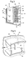
- Vane 20 is hollow and contains a perforated tube 26, which extends through the greater portion thereof, as is more clearly seen in Fig 3.
- Each vane 20 also contains a stack of webs 28, which span the interior space defined by the side walls of vane 20. Further webs 30 span a slot 32 which extends for the full length of the trailing edge 34 of vane 20, and their sole function is to support the thin trailing edge 34 against deformation under gas loads.
- tube 26 is perforated in known manner, and during operation of vane 20 in an associated gas turbine engine 10, compressor air is delivered to the interior of tube 26,via its upper end 36. The air then bleeds through the perforations 38, only a few of which are shown, into the interior of vane 20, so as to cool the inner surfaces thereof. The cooling air then flows in a downstream direction, with respect to the direction of gas flow through the associated engine 10, to enter a stack of ducts 40, the cross sectional shapes and areas of which are defined by the inner surfaces of the side walls of vane 20, and the facing surfaces of adjacent pairs of webs 28.
- protuberances 42 of a particular shape are provided in each duct 40 i.e. the protuberances 42 are elongate and rectangular in cross section.
- the protuberances 42 are arranged in alternating manner, both in the direction of air flow and transversely thereto. Their function is to generate turbulence in the cooling air as it flows over them, after leaving tube 26, thus enabling the extraction of more heat from the side walls of vane20.
- the converging ducts 40 in which the turbulence occurs serve to increase the speed of the air flow prior to leaving them, to a level greater than has been attained in prior art examples, which in turn enhances heat extraction and reduces the pressure losses when mixed with the main stream gas, relative to the losses experienced in the said prior art.
- the present invention offers the following advantages over known prior art:
Landscapes
- Engineering & Computer Science (AREA)
- Mechanical Engineering (AREA)
- General Engineering & Computer Science (AREA)
- Turbine Rotor Nozzle Sealing (AREA)
Abstract
Description
Claims (6)
- A gas turbine engine guide vane (20) comprising a hollow aerofoil containing a stack of cooling air flow ducts (40) aligned chordally of the aerofoil and defined in part by the inner wall surfaces of said aerofoil, and in part by webs (28) which span the space between said inner wall surfaces, characterised in that said webs (28) are so shaped that their facing surfaces converge in a direction towards the trailing edge (34) of said aerofoil.
- A gas turbine engine guide vane as claimed in claim 1 characterised in that air flow turbulence generating means (42) are provided in said ducts (40).
- A gas turbine engine guide vane as claimed in claim 2 characterised in that said turbulence generating means (40) comprises elongate protuberances.
- A gas turbine engine guide vane as claimed in claim 3 characterised in that said protuberances (40) are positioned in said ducts (40) with their major dimensions normal to the vane (20) chordal plane.
- A gas turbine engine guide vane as claimed in claim 3 or claim 4 characterised in that said protuberances (40) are rectangular in planes normal to their major dimensions.
- A gas turbine engine guide vane as claimed in claim 1 characterised in that air flow turbulence generating means (42) are provided therewithin, some of which are external to, but aligned with said ducts, upstream thereof, the remainder being in said ducts.
Applications Claiming Priority (2)
| Application Number | Priority Date | Filing Date | Title |
|---|---|---|---|
| GB0105814 | 2001-03-09 | ||
| GBGB0105814.8A GB0105814D0 (en) | 2001-03-09 | 2001-03-09 | Gas turbine engine guide vane |
Publications (3)
| Publication Number | Publication Date |
|---|---|
| EP1239120A2 true EP1239120A2 (en) | 2002-09-11 |
| EP1239120A3 EP1239120A3 (en) | 2004-09-01 |
| EP1239120B1 EP1239120B1 (en) | 2006-02-01 |
Family
ID=9910301
Family Applications (1)
| Application Number | Title | Priority Date | Filing Date |
|---|---|---|---|
| EP02251137A Expired - Lifetime EP1239120B1 (en) | 2001-03-09 | 2002-02-20 | Gas turbine engine guide vane |
Country Status (4)
| Country | Link |
|---|---|
| US (1) | US6616407B2 (en) |
| EP (1) | EP1239120B1 (en) |
| DE (1) | DE60208977T2 (en) |
| GB (1) | GB0105814D0 (en) |
Cited By (2)
| Publication number | Priority date | Publication date | Assignee | Title |
|---|---|---|---|---|
| WO2008107401A1 (en) * | 2007-03-06 | 2008-09-12 | Siemens Aktiengesellschaft | Guide vane duct element for a guide vane assembly of a gas turbine engine |
| EP2832956A1 (en) * | 2013-07-29 | 2015-02-04 | Siemens Aktiengesellschaft | Turbine blade with airfoil-shaped cooling bodies |
Families Citing this family (2)
| Publication number | Priority date | Publication date | Assignee | Title |
|---|---|---|---|---|
| US7189060B2 (en) * | 2005-01-07 | 2007-03-13 | Siemens Power Generation, Inc. | Cooling system including mini channels within a turbine blade of a turbine engine |
| US7722327B1 (en) | 2007-04-03 | 2010-05-25 | Florida Turbine Technologies, Inc. | Multiple vortex cooling circuit for a thin airfoil |
Family Cites Families (4)
| Publication number | Priority date | Publication date | Assignee | Title |
|---|---|---|---|---|
| US3171631A (en) * | 1962-12-05 | 1965-03-02 | Gen Motors Corp | Turbine blade |
| WO1994012768A2 (en) * | 1992-11-24 | 1994-06-09 | United Technologies Corporation | Coolable airfoil structure |
| US5288207A (en) * | 1992-11-24 | 1994-02-22 | United Technologies Corporation | Internally cooled turbine airfoil |
| US5772397A (en) * | 1996-05-08 | 1998-06-30 | Alliedsignal Inc. | Gas turbine airfoil with aft internal cooling |
-
2001
- 2001-03-09 GB GBGB0105814.8A patent/GB0105814D0/en not_active Ceased
-
2002
- 2002-02-20 EP EP02251137A patent/EP1239120B1/en not_active Expired - Lifetime
- 2002-02-20 DE DE60208977T patent/DE60208977T2/en not_active Expired - Lifetime
- 2002-02-21 US US10/078,672 patent/US6616407B2/en not_active Expired - Lifetime
Cited By (8)
| Publication number | Priority date | Publication date | Assignee | Title |
|---|---|---|---|---|
| WO2008107401A1 (en) * | 2007-03-06 | 2008-09-12 | Siemens Aktiengesellschaft | Guide vane duct element for a guide vane assembly of a gas turbine engine |
| EP1975373A1 (en) * | 2007-03-06 | 2008-10-01 | Siemens Aktiengesellschaft | Guide vane duct element for a guide vane assembly of a gas turbine engine |
| CN101622423B (en) * | 2007-03-06 | 2012-06-20 | 西门子公司 | Guide vane duct element for a guide vane assembly of a gas turbine engine |
| US8403626B2 (en) | 2007-03-06 | 2013-03-26 | Siemens Aktiengesellschaft | Arrangement for a gas turbine engine |
| EP2832956A1 (en) * | 2013-07-29 | 2015-02-04 | Siemens Aktiengesellschaft | Turbine blade with airfoil-shaped cooling bodies |
| WO2015014566A1 (en) * | 2013-07-29 | 2015-02-05 | Siemens Aktiengesellschaft | Turbine blade having heat sinks that have the shape of an aerofoil profile |
| CN105408586A (en) * | 2013-07-29 | 2016-03-16 | 西门子股份公司 | Turbine blade having heat sinks that have the shape of aerofoil profile |
| CN105408586B (en) * | 2013-07-29 | 2017-06-16 | 西门子股份公司 | Turbo blade with aerofoil profile shape radiator |
Also Published As
| Publication number | Publication date |
|---|---|
| DE60208977D1 (en) | 2006-04-13 |
| US20020127095A1 (en) | 2002-09-12 |
| DE60208977T2 (en) | 2006-07-27 |
| EP1239120B1 (en) | 2006-02-01 |
| EP1239120A3 (en) | 2004-09-01 |
| GB0105814D0 (en) | 2001-04-25 |
| US6616407B2 (en) | 2003-09-09 |
Similar Documents
| Publication | Publication Date | Title |
|---|---|---|
| US12565842B2 (en) | Airfoil having a film hole | |
| CN101646841B (en) | Eccentric chamfer at the branch inlet in the runner | |
| US5337568A (en) | Micro-grooved heat transfer wall | |
| US8210812B2 (en) | Advanced turbulator arrangements for microcircuits | |
| US4515526A (en) | Coolable airfoil for a rotary machine | |
| US8167560B2 (en) | Turbine airfoil with an internal cooling system having enhanced vortex forming turbulators | |
| US6672836B2 (en) | Coolable rotor blade for an industrial gas turbine engine | |
| JP5826516B2 (en) | System and method for facilitating mixing of turbine wakes using fluidly generated vortices | |
| CA2528098C (en) | Internally cooled gas turbine airfoil and method | |
| CN107429568B (en) | Internal cooling system with converging-diverging outlet slots in trailing-edge cooling passages for airfoils in turbine engines | |
| US7637720B1 (en) | Turbulator for a turbine airfoil cooling passage | |
| EP1091092A2 (en) | Method and apparatus for cooling a wall within a gas turbine engine | |
| EP1302628A2 (en) | Airfoil with indentations to enhance heat transfer | |
| US6997675B2 (en) | Turbulated hole configurations for turbine blades | |
| EP1873354A2 (en) | Leading edge cooling using chevron trip strips | |
| CN106133276B (en) | Turbine airfoil | |
| US8920122B2 (en) | Turbine airfoil with an internal cooling system having vortex forming turbulators | |
| JP2016128687A (en) | Engine component | |
| JP2001164903A (en) | Airfoil, wall capable of being cooled, and method of cooling the wall | |
| US20140286791A1 (en) | Component Cooling Channel | |
| EP0992654A3 (en) | Coolant passages for gas turbine components | |
| EP2110515A2 (en) | Cooling arrangement between two blade platforms for a gas turbine engine | |
| US7156620B2 (en) | Internally cooled gas turbine airfoil and method | |
| CN112459852B (en) | Be applied to two water conservancy diversion rib water conservancy diversion structures of turbine blade trailing edge half-splitting seam | |
| EP1687511A1 (en) | High lift rotor or stator blades with multiple adjacent airfoils cross-section |
Legal Events
| Date | Code | Title | Description |
|---|---|---|---|
| PUAI | Public reference made under article 153(3) epc to a published international application that has entered the european phase |
Free format text: ORIGINAL CODE: 0009012 |
|
| AK | Designated contracting states |
Kind code of ref document: A2 Designated state(s): AT BE CH CY DE DK ES FI FR GB GR IE IT LI LU MC NL PT SE TR |
|
| AX | Request for extension of the european patent |
Free format text: AL;LT;LV;MK;RO;SI |
|
| PUAL | Search report despatched |
Free format text: ORIGINAL CODE: 0009013 |
|
| AK | Designated contracting states |
Kind code of ref document: A3 Designated state(s): AT BE CH CY DE DK ES FI FR GB GR IE IT LI LU MC NL PT SE TR |
|
| AX | Request for extension of the european patent |
Extension state: AL LT LV MK RO SI |
|
| 17P | Request for examination filed |
Effective date: 20040726 |
|
| 17Q | First examination report despatched |
Effective date: 20050119 |
|
| AKX | Designation fees paid |
Designated state(s): DE FR GB |
|
| GRAP | Despatch of communication of intention to grant a patent |
Free format text: ORIGINAL CODE: EPIDOSNIGR1 |
|
| RBV | Designated contracting states (corrected) |
Designated state(s): DE FR GB |
|
| GRAS | Grant fee paid |
Free format text: ORIGINAL CODE: EPIDOSNIGR3 |
|
| GRAA | (expected) grant |
Free format text: ORIGINAL CODE: 0009210 |
|
| AK | Designated contracting states |
Kind code of ref document: B1 Designated state(s): DE FR GB |
|
| REG | Reference to a national code |
Ref country code: GB Ref legal event code: FG4D |
|
| REF | Corresponds to: |
Ref document number: 60208977 Country of ref document: DE Date of ref document: 20060413 Kind code of ref document: P |
|
| ET | Fr: translation filed | ||
| PLBE | No opposition filed within time limit |
Free format text: ORIGINAL CODE: 0009261 |
|
| STAA | Information on the status of an ep patent application or granted ep patent |
Free format text: STATUS: NO OPPOSITION FILED WITHIN TIME LIMIT |
|
| 26N | No opposition filed |
Effective date: 20061103 |
|
| REG | Reference to a national code |
Ref country code: FR Ref legal event code: PLFP Year of fee payment: 14 |
|
| REG | Reference to a national code |
Ref country code: FR Ref legal event code: PLFP Year of fee payment: 15 |
|
| REG | Reference to a national code |
Ref country code: FR Ref legal event code: PLFP Year of fee payment: 16 |
|
| PGFP | Annual fee paid to national office [announced via postgrant information from national office to epo] |
Ref country code: DE Payment date: 20170227 Year of fee payment: 16 |
|
| REG | Reference to a national code |
Ref country code: FR Ref legal event code: PLFP Year of fee payment: 17 |
|
| REG | Reference to a national code |
Ref country code: DE Ref legal event code: R119 Ref document number: 60208977 Country of ref document: DE |
|
| PG25 | Lapsed in a contracting state [announced via postgrant information from national office to epo] |
Ref country code: DE Free format text: LAPSE BECAUSE OF NON-PAYMENT OF DUE FEES Effective date: 20180901 |
|
| PGFP | Annual fee paid to national office [announced via postgrant information from national office to epo] |
Ref country code: FR Payment date: 20210223 Year of fee payment: 20 |
|
| PGFP | Annual fee paid to national office [announced via postgrant information from national office to epo] |
Ref country code: GB Payment date: 20210223 Year of fee payment: 20 |
|
| REG | Reference to a national code |
Ref country code: GB Ref legal event code: PE20 Expiry date: 20220219 |
|
| PG25 | Lapsed in a contracting state [announced via postgrant information from national office to epo] |
Ref country code: GB Free format text: LAPSE BECAUSE OF EXPIRATION OF PROTECTION Effective date: 20220219 |