EP1239119A1 - Turbine vane assembly including a low ductility vane - Google Patents
Turbine vane assembly including a low ductility vane Download PDFInfo
- Publication number
- EP1239119A1 EP1239119A1 EP02250055A EP02250055A EP1239119A1 EP 1239119 A1 EP1239119 A1 EP 1239119A1 EP 02250055 A EP02250055 A EP 02250055A EP 02250055 A EP02250055 A EP 02250055A EP 1239119 A1 EP1239119 A1 EP 1239119A1
- Authority
- EP
- European Patent Office
- Prior art keywords
- vane
- support
- assembly
- cte
- support opening
- Prior art date
- Legal status (The legal status is an assumption and is not a legal conclusion. Google has not performed a legal analysis and makes no representation as to the accuracy of the status listed.)
- Granted
Links
- 239000000463 material Substances 0.000 claims abstract description 68
- 239000011153 ceramic matrix composite Substances 0.000 claims abstract description 16
- 229910000943 NiAl Inorganic materials 0.000 claims abstract description 11
- NPXOKRUENSOPAO-UHFFFAOYSA-N Raney nickel Chemical compound [Al].[Ni] NPXOKRUENSOPAO-UHFFFAOYSA-N 0.000 claims abstract description 11
- 239000000919 ceramic Substances 0.000 claims abstract description 9
- 229910001092 metal group alloy Inorganic materials 0.000 claims description 14
- 239000012530 fluid Substances 0.000 claims description 9
- 238000007789 sealing Methods 0.000 claims description 5
- 230000008602 contraction Effects 0.000 abstract description 5
- 238000001816 cooling Methods 0.000 description 12
- 229910045601 alloy Inorganic materials 0.000 description 10
- 239000000956 alloy Substances 0.000 description 10
- 229910000601 superalloy Inorganic materials 0.000 description 7
- 239000002184 metal Substances 0.000 description 5
- 229910052751 metal Inorganic materials 0.000 description 5
- 238000005219 brazing Methods 0.000 description 3
- 230000015556 catabolic process Effects 0.000 description 3
- 238000002485 combustion reaction Methods 0.000 description 3
- 238000006731 degradation reaction Methods 0.000 description 3
- 230000007613 environmental effect Effects 0.000 description 3
- 239000000835 fiber Substances 0.000 description 3
- 230000000977 initiatory effect Effects 0.000 description 3
- 238000003466 welding Methods 0.000 description 3
- 208000010392 Bone Fractures Diseases 0.000 description 2
- 206010017076 Fracture Diseases 0.000 description 2
- VYPSYNLAJGMNEJ-UHFFFAOYSA-N Silicium dioxide Chemical compound O=[Si]=O VYPSYNLAJGMNEJ-UHFFFAOYSA-N 0.000 description 2
- PNEYBMLMFCGWSK-UHFFFAOYSA-N aluminium oxide Inorganic materials [O-2].[O-2].[O-2].[Al+3].[Al+3] PNEYBMLMFCGWSK-UHFFFAOYSA-N 0.000 description 2
- 239000011248 coating agent Substances 0.000 description 2
- 238000000576 coating method Methods 0.000 description 2
- 230000008439 repair process Effects 0.000 description 2
- 208000013201 Stress fracture Diseases 0.000 description 1
- 238000005299 abrasion Methods 0.000 description 1
- 230000000712 assembly Effects 0.000 description 1
- 238000000429 assembly Methods 0.000 description 1
- 229910010293 ceramic material Inorganic materials 0.000 description 1
- 239000002131 composite material Substances 0.000 description 1
- 230000003247 decreasing effect Effects 0.000 description 1
- 230000007547 defect Effects 0.000 description 1
- 230000003628 erosive effect Effects 0.000 description 1
- 238000011156 evaluation Methods 0.000 description 1
- 229910000856 hastalloy Inorganic materials 0.000 description 1
- 239000011159 matrix material Substances 0.000 description 1
- 230000001590 oxidative effect Effects 0.000 description 1
- 239000000377 silicon dioxide Substances 0.000 description 1
- 239000000758 substrate Substances 0.000 description 1
Images



Classifications
-
- F—MECHANICAL ENGINEERING; LIGHTING; HEATING; WEAPONS; BLASTING
- F01—MACHINES OR ENGINES IN GENERAL; ENGINE PLANTS IN GENERAL; STEAM ENGINES
- F01D—NON-POSITIVE DISPLACEMENT MACHINES OR ENGINES, e.g. STEAM TURBINES
- F01D9/00—Stators
- F01D9/02—Nozzles; Nozzle boxes; Stator blades; Guide conduits, e.g. individual nozzles
- F01D9/04—Nozzles; Nozzle boxes; Stator blades; Guide conduits, e.g. individual nozzles forming ring or sector
- F01D9/042—Nozzles; Nozzle boxes; Stator blades; Guide conduits, e.g. individual nozzles forming ring or sector fixing blades to stators
-
- F—MECHANICAL ENGINEERING; LIGHTING; HEATING; WEAPONS; BLASTING
- F01—MACHINES OR ENGINES IN GENERAL; ENGINE PLANTS IN GENERAL; STEAM ENGINES
- F01D—NON-POSITIVE DISPLACEMENT MACHINES OR ENGINES, e.g. STEAM TURBINES
- F01D5/00—Blades; Blade-carrying members; Heating, heat-insulating, cooling or antivibration means on the blades or the members
- F01D5/30—Fixing blades to rotors; Blade roots ; Blade spacers
- F01D5/3084—Fixing blades to rotors; Blade roots ; Blade spacers the blades being made of ceramics
Definitions
- This invention relates to turbine vane assemblies, for example of the type used in gas turbine engines. More particularly in one embodiment, it relates to a turbine vane assembly including at least one low ductility vane carried at least in part by a compliant seal to enable expansion and contraction of the vane independently from at least one of spaced apart metal supports or bands.
- Components in sections of gas turbine engines operating at elevated temperatures in a strenuous, oxidizing type of gas flow environment typically are made of high temperature superalloys such as those based on at least one of Fe, Co, and Ni.
- high temperature superalloys such as those based on at least one of Fe, Co, and Ni.
- a turbine stator vane assembly used as a turbine section nozzle downstream of a turbine engine combustion section.
- such assembly is made of a plurality of metal alloy segments each including a plurality of airfoil shaped hollow air cooled metal alloy vanes, for example two to four vanes, bonded, such as by welding or brazing, to spaced apart metal alloy inner and outer bands.
- the segments are assembled circumferentially into a stator nozzle assembly.
- One type of such gas turbine engine nozzle assembly is shown and described in U. S. Patent 5,343,694 - Toberg et al. (patented September 6, 1994).
- the present invention provides a turbine vane assembly comprising an outer vane support, an inner vane support in a fixed spaced apart position from the outer vane support, and at least one airfoil shaped vane supported between the outer and inner vane supports.
- the vane is of a low ductility material, for example based on a ceramic matrix composite or an intermetallic material, having a room temperature ductility no greater than about 1%.
- the outer and inner vane supports are of material having a room temperature ductility of at least about 5%.
- a high temperature resistant compliant seal is disposed between the vane and at least one of the vane supports, substantially sealing the vane from passage of fluid between the vane and the vane support, enabling the vane to expand and contract independently of the vane support.
- the vane supports are of a high temperature metal alloy, for example based on at least one of Fe, Co, and Ni, having a room temperature tensile ductility in the range of about 5 ⁇ 15%.
- Certain ceramic base and intermetallic type of high temperature resistant materials including monolithic as well as intermetallic base and ceramic based composites, have been developed with adequate strength properties along with improved environmental resistance to enable them to be attractive for use in the strenuous type of environment existing in hot sections of a turbine engine.
- such materials have the common property of being very low in tensile ductility compared with high temperature metal alloys generally used for their support structures.
- coefficients of thermal expansion between such materials and alloys, for example between low ductility ceramic matrix composites (CMC) or intermetallic materials based on NiAl, and typical commercial Ni base and Co base superalloys currently used as supports in such engine sections.
- a typical Ni base superalloy such as commercially available Rene' N5 alloy, forms of which are described in U.S Patent 5,173,255 ⁇ Ross et al., and used in gas turbine engine turbine components, has a room temperature tensile ductility in the range of about 5 ⁇ 15% (with a CTE in the range of about 7 ⁇ 10 microinch/inch/°F).
- the low ductility materials have a room temperature tensile ductility of no greater than about 1% (with a CTE in the range of about 1.5 ⁇ 8.5 microinch/inch/°F).
- a typical commercially available low ductility ceramic matrix composite (CMC) material such as SiC fiber / SiC matrix CMC has a room temperature tensile ductility in the range of about 0.4 - 0.7%, and a CTE in the range of about 1.5 ⁇ 5 microinch/inch/°F.
- a low ductility NiAl type intermetallic material has near zero tensile ductility, in the range of about 0.1 ⁇ 1%, with a CTE of about 8 ⁇ 10 microinch/inch/°F. Therefore, according to the present invention, a low ductility material is defined as one having a room tensile ductility of no greater than about 1%.
- CTE's between the low ductility material and one or more high temperature alloy support materials shows that the ratio of the average of the CTE's of the more ductile support alloys to the CTE of the low ductility material is at least about 0.8.
- Typical examples of such ratios for a Ni base superalloy to CMC low ductility material are in the range of about 1.4 ⁇ 6.7 and to NiAl low ductility material are in the range of about 0.8 ⁇ 1.2.
- Ductility represents plastic elongation or deformation required to prevent initiation of cracks, for example for brittle materials under local or point loading.
- fracture toughness represents the ability of the material to minimize or resist propagation in the presence of an existing crack or defect.
- the low ductility material is defined as having a fracture toughness of less than about 20 ksi ⁇ inch 1/2 in which "ksi" is thousands of pounds per square inch.
- the CMC materials have a fracture toughness in the range of about 5 ⁇ 20 ksi ⁇ inch 1/2 ; and the NiAl intermetallic materials have a fracture toughness in the range of about 5 ⁇ 10 ksi ⁇ inch 1/2 .
- a form of the present invention provides a combination of members and materials that compliantly and releasably captures a low ductility member such as a CMC or intermetallic base turbine vane within a supporting structure such as a superalloy band, avoiding generation of excessive thermal strain in the low ductility material.
- a compliant seal is disposed between and in contact both with at least one end of the low ductility vane and a support in juxtaposition with the end. Concurrently the compliant seal prevents flow of fluid such as air and/or products of combustion between the vane end and the support while isolating the low ductility vane from the support and enabling each to expand and contract from thermal exposure independent of one another.
- rope seals In forms for use at elevated temperatures, rope seals include woven or braided ceramic fibers or filaments, forms of which are commercially available as Nextel alumina material and as Zircar alumina silica material. Some forms of the compliant seals, for example for strength and/or resistance to surface abrasion, include one or more of the combination of a metallic core, such as a wire of commercial Hastelloy X alloy, within the ceramic filaments and/or an outer sheath of thin, ductile metal about the ceramic filaments. The woven or braided structure of the ceramic fibers or filaments provide compliance and resilience.
- a metallic core such as a wire of commercial Hastelloy X alloy
- FIG. 1 is a perspective view of a gas turbine engine turbine stator vane segment or assembly shown generally at 10 including four airfoil shaped vanes 12 disposed between an outer vane support or band 14 and a fixed position spaced apart inner vane support or band 16.
- the vanes and vane supports each are made of a high temperature alloy and bonded together, as shown, by welding and/or brazing. This secures the vanes with the bands in a fixed relative position and prevents leakage of the engine flow stream from the flow path through the bands.
- a plurality of matching vane segments is assembled circumferentially into a turbine nozzle, for example as shown in the above-identified Toberg et al. patent.
- vanes 12, as shown in the sectional view of Figure 2 along lines 2 ⁇ 2 of Figure 1, include a hollow interior 18 to receive and distribute cooling air through and from the vane interior.
- a vane insert 20, shown in Figure 6, is disposed in vane hollow interior 18 to distribute cooling air within and through vane 12 and through cooling air discharge openings (not shown), generally included through the vane wall.
- Vane 12 is made of a low ductility material of the type described above, in the drawings represented as a ceramic material.
- Vane 12 includes a vane radially outer end 22 and a vane radially inner end 24.
- Metal alloy outer vane support 14 includes therein an opening 28 defined by outer opening wall 30 sized generally to receive outer end 22 of vane 12.
- Metal alloy inner vane support 16 includes therein an opening 32 defined by inner opening wall 34 sized generally to receive inner end 24 of vane 12.
- Outer vane support 14 and inner vane support 16 are held in a fixed spaced apart position in respect to one another.
- a positioning means can include at least one of a rigid metal bolt, tube, rod, strut, etc.
- first compliant seal 36 Disposed between and in contact with both vane outer end 22 and outer opening wall 30 is first compliant seal 36.
- Seal 36 carries vane outer end 22 within opening 28 independently from outer opening wall 30 to enable independent relative movement between vane 12 and outer support 14. For example such relative movement can result from different expansion and contraction rates between juxtaposed materials during engine operation.
- seal 36 substantially seals vane end 22 from passage thereabout of fluid from the engine flow stream.
- seal 38 disposed between and in contact with both vane inner end 24 and inner opening wall 34 is a second compliant seal 38.
- Seal 38 carries vane inner end 24 within opening 32 independently from inner opening wall 34 to enable independent relative movement between vane 12 and inner support 16. Concurrently, seal 38 substantially seals vane end 24 from passage thereabout of fluid from the engine flow stream.
- Such disposition of the compliant seal or seals in Figure 3 captures vane 12 between outer band 14 and inner band 16 while enabling independent thermal expansion and contraction of the vane and the supports.
- the compliance of the seals avoids application of compressive stress to vane 12, avoiding stress fracture of the vane.
- an outer seal retainer 40 securely bonded with outer support 14, for example by welding or brazing. Seal retainer 40 holds seal 36 in position between vane outer end 22 and outer support opening wall 30.
- an inner seal retainer 42 similarly bonded with inner support 16, to hold seal 38 in position between vane inner end 24 and inner support opening wall 34.
- Figure 4 is a diagrammatic fragmentary top view of a portion of Figure 3 before bonding of outer seal retainer 40 to outer support 14.
- Figure 4 shows the general airfoil shape of vane outer end 22 and the position or disposition of compliant seal 36 about the vane end.
- Figure 5 is a diagrammatic, enlarged fragmentary sectional view of another embodiment of the present invention including the same general members as in Figure 3.
- Figure 5 shows more clearly a space 44 between at least one end of vane 12 and a seal retainer to enable independent expansion and contraction of vane 12 in respect to the metal supporting structure.
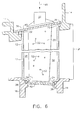
- FIG. 6 is a diagrammatic, fragmentary view as in Figure 3, partially sectional to show insert 20 disposed in vane hollow interior 18.
- Insert 20 provides air for cooling to and through hollow interior 18 of vane 12.
- cooling air represented by arrow 48 is provided through cup-like structure 50 to insert 20 within vane 12.
- Cooling air is distributed by insert 20 within hollow interior 18 through a plurality of insert openings, some of which are shown at 52.
- cooling air is discharged from vane hollow interior 18 through cooling air openings (not shown) through walls of vane 12 and/or through openings (not shown) through at least one seal retainer, in a manner well known and widely used in the gas turbine engine art.
- insert 16 first is bonded with outer seal retainer 40 through an appropriately shaped opening in retainer 40 to provide a combination seal retainer and cooling air insert for assembly and bonding as a unit to outer support 14.
- FIG. 7 is a diagrammatic, fragmentary, partially sectional view of another embodiment of the present invention.
- vane 12 for example of an NiAl low ductility intermetallic material, is secured at its radially inner end 24 by the combination of an NiAl vane end cap 54 and a metal pin, washer and pad assembly shown generally at 56.
- outer end 22 of vane 12 is releasably and compliantly held, as described above, by compliant seal 36 to enable vane 12 to expand and contract independently of outer support 14.
Landscapes
- Engineering & Computer Science (AREA)
- Mechanical Engineering (AREA)
- General Engineering & Computer Science (AREA)
- Chemical & Material Sciences (AREA)
- Ceramic Engineering (AREA)
- Turbine Rotor Nozzle Sealing (AREA)
Abstract
Description
- This invention relates to turbine vane assemblies, for example of the type used in gas turbine engines. More particularly in one embodiment, it relates to a turbine vane assembly including at least one low ductility vane carried at least in part by a compliant seal to enable expansion and contraction of the vane independently from at least one of spaced apart metal supports or bands.
- Components in sections of gas turbine engines operating at elevated temperatures in a strenuous, oxidizing type of gas flow environment typically are made of high temperature superalloys such as those based on at least one of Fe, Co, and Ni. In order to resist degradation of the metal alloy of such components, it has been common practice to provide such components with a combination of fluid or air cooling and surface environmental protection or coating, of various widely reported types and combinations.
- One type of such a gas turbine engine component is a turbine stator vane assembly used as a turbine section nozzle downstream of a turbine engine combustion section. Generally, such assembly is made of a plurality of metal alloy segments each including a plurality of airfoil shaped hollow air cooled metal alloy vanes, for example two to four vanes, bonded, such as by welding or brazing, to spaced apart metal alloy inner and outer bands. The segments are assembled circumferentially into a stator nozzle assembly. One type of such gas turbine engine nozzle assembly is shown and described in U. S. Patent 5,343,694 - Toberg et al. (patented September 6, 1994).
- From evaluation of service operated turbine nozzles made of coated high temperature superalloys, it has been observed that the strenuous, high temperature, erosive and corrosive conditions existing in the engine flow path downstream of a gas turbine engine combustion section can result in degradation of the environmental resistant coating and/or alloy substrate structure of vanes of the nozzle. Repair or replacement of one or more of the vanes has been required prior to returning such a component to service operation. Provision of turbine vanes of adequate strength and more resistant to such degradation would extend component life and time between necessary repairs, decreasing cost of operation of such an engine.
- In one form, the present invention provides a turbine vane assembly comprising an outer vane support, an inner vane support in a fixed spaced apart position from the outer vane support, and at least one airfoil shaped vane supported between the outer and inner vane supports. The vane is of a low ductility material, for example based on a ceramic matrix composite or an intermetallic material, having a room temperature ductility no greater than about 1%. The outer and inner vane supports are of material having a room temperature ductility of at least about 5%. A high temperature resistant compliant seal is disposed between the vane and at least one of the vane supports, substantially sealing the vane from passage of fluid between the vane and the vane support, enabling the vane to expand and contract independently of the vane support. In one form, the vane supports are of a high temperature metal alloy, for example based on at least one of Fe, Co, and Ni, having a room temperature tensile ductility in the range of about 5 ― 15%.
- Embodiments of the invention will now be described, by way of example, with reference to the accompanying drawings, in which:
- Figure 1 is a perspective view of a typical gas turbine engine nozzle vane segment.
- Figure 2 is a sectional view of the vane segment of Figure 1 along
lines 2 ― 2 of Figure 1. - Figure 3 is a diagrammatic, fragmentary sectional view of one embodiment of the present invention showing a low ductility vane carried by compliant seals between outer and inner metal alloy vane supports.
- Figure 4 is diagrammatic top view of the vane of Figure 3 before an outer seal retainer has been applied.
- Figure 5 is a diagrammatic, fragmentary sectional view of another embodiment of the present invention.
- Figure 6 is a view as in Figure 3 with a cooling air insert disposed within the vane hollow interior.
- Figure 7 is a diagrammatic, fragmentary, partially sectional view of another embodiment of the present invention showing a low ductility vane carried at its radially inner end by a fixed arrangement and releasably carried at its radially outer end by a compliant seal between its outer end and an outer metal alloy vane support.
-
- Certain ceramic base and intermetallic type of high temperature resistant materials, including monolithic as well as intermetallic base and ceramic based composites, have been developed with adequate strength properties along with improved environmental resistance to enable them to be attractive for use in the strenuous type of environment existing in hot sections of a turbine engine. However, such materials have the common property of being very low in tensile ductility compared with high temperature metal alloys generally used for their support structures. In addition, there generally is a significant difference in coefficients of thermal expansion (CTE) between such materials and alloys, for example between low ductility ceramic matrix composites (CMC) or intermetallic materials based on NiAl, and typical commercial Ni base and Co base superalloys currently used as supports in such engine sections.
- If such low ductility materials are rigidly supported by such high temperature alloy structures, thermal strains can be generated in the low ductility material from the mismatch of properties in an amount that can result in fracture of the low ductility material. For example, a typical Ni base superalloy such as commercially available Rene' N5 alloy, forms of which are described in U.S Patent 5,173,255 ― Ross et al., and used in gas turbine engine turbine components, has a room temperature tensile ductility in the range of about 5 ― 15% (with a CTE in the range of about 7 ― 10 microinch/inch/°F). The low ductility materials have a room temperature tensile ductility of no greater than about 1% (with a CTE in the range of about 1.5 ― 8.5 microinch/inch/°F). For example, a typical commercially available low ductility ceramic matrix composite (CMC) material such as SiC fiber / SiC matrix CMC has a room temperature tensile ductility in the range of about 0.4 - 0.7%, and a CTE in the range of about 1.5 ― 5 microinch/inch/°F. Similarly, a low ductility NiAl type intermetallic material has near zero tensile ductility, in the range of about 0.1 ― 1%, with a CTE of about 8 ― 10 microinch/inch/°F. Therefore, according to the present invention, a low ductility material is defined as one having a room tensile ductility of no greater than about 1%.
- In addition to such significant differences in room temperature ductility, comparison of CTE's between the low ductility material and one or more high temperature alloy support materials, for example superalloys based on at least one of Fe, Co, and Ni, shows that the ratio of the average of the CTE's of the more ductile support alloys to the CTE of the low ductility material is at least about 0.8. Typical examples of such ratios for a Ni base superalloy to CMC low ductility material are in the range of about 1.4 ― 6.7 and to NiAl low ductility material are in the range of about 0.8 ― 1.2.
- Thus there is a significant difference or mismatch in such properties between a low ductility material and such an alloy support. Rigid, fixed assembly of such materials such as a low ductility vane between high temperature alloy supports in a turbine vane assembly can enable generation in the vane of a thermal strain sufficient to result in fracture or crack initiation in the vane during engine operation. Therefore, it is desirable to avoid crack initiation in a low ductility material.
- Ductility represents plastic elongation or deformation required to prevent initiation of cracks, for example for brittle materials under local or point loading. However another mechanical property, fracture toughness, represents the ability of the material to minimize or resist propagation in the presence of an existing crack or defect. In one form, the low ductility material is defined as having a fracture toughness of less than about 20 ksi·inch1/2 in which "ksi" is thousands of pounds per square inch. Typically, the CMC materials have a fracture toughness in the range of about 5 ― 20 ksi·inch1/2; and the NiAl intermetallic materials have a fracture toughness in the range of about 5 ― 10 ksi·inch1/2.
- A form of the present invention provides a combination of members and materials that compliantly and releasably captures a low ductility member such as a CMC or intermetallic base turbine vane within a supporting structure such as a superalloy band, avoiding generation of excessive thermal strain in the low ductility material. In that form of the combination, a compliant seal is disposed between and in contact both with at least one end of the low ductility vane and a support in juxtaposition with the end. Concurrently the compliant seal prevents flow of fluid such as air and/or products of combustion between the vane end and the support while isolating the low ductility vane from the support and enabling each to expand and contract from thermal exposure independent of one another.
- Forms of the compliant seal used in the present invention sometimes are referred to as rope seals. Typical rope seal stress-strain curves comparing deflection of the seal at different loads confirm the compliance and resilience of such a seal. In forms for use at elevated temperatures, rope seals include woven or braided ceramic fibers or filaments, forms of which are commercially available as Nextel alumina material and as Zircar alumina silica material. Some forms of the compliant seals, for example for strength and/or resistance to surface abrasion, include one or more of the combination of a metallic core, such as a wire of commercial Hastelloy X alloy, within the ceramic filaments and/or an outer sheath of thin, ductile metal about the ceramic filaments. The woven or braided structure of the ceramic fibers or filaments provide compliance and resilience.
- The present invention will be more fully understood by reference to the drawings. Figure 1 is a perspective view of a gas turbine engine turbine stator vane segment or assembly shown generally at 10 including four airfoil shaped
vanes 12 disposed between an outer vane support orband 14 and a fixed position spaced apart inner vane support orband 16. In a typical current commercial gas turbine engine, the vanes and vane supports each are made of a high temperature alloy and bonded together, as shown, by welding and/or brazing. This secures the vanes with the bands in a fixed relative position and prevents leakage of the engine flow stream from the flow path through the bands. A plurality of matching vane segments is assembled circumferentially into a turbine nozzle, for example as shown in the above-identified Toberg et al. patent. - To enable air cooling of each
segment 10,vanes 12, as shown in the sectional view of Figure 2 alonglines 2 ― 2 of Figure 1, include ahollow interior 18 to receive and distribute cooling air through and from the vane interior. In some embodiments, avane insert 20, shown in Figure 6, is disposed in vanehollow interior 18 to distribute cooling air within and throughvane 12 and through cooling air discharge openings (not shown), generally included through the vane wall. - One embodiment of the present invention is shown in the diagrammatic, fragmentary sectional view of Figure 3. Vane 12 is made of a low ductility material of the type described above, in the drawings represented as a ceramic material. Vane 12 includes a vane radially
outer end 22 and a vane radiallyinner end 24. Metal alloyouter vane support 14 includes therein an opening 28 defined byouter opening wall 30 sized generally to receiveouter end 22 ofvane 12. Metal alloyinner vane support 16 includes therein anopening 32 defined by inneropening wall 34 sized generally to receiveinner end 24 ofvane 12.Outer vane support 14 andinner vane support 16 are held in a fixed spaced apart position in respect to one another. If all of thevanes 12 are of a low ductility material not rigidly held between outer and inner vane supports 14 and 16, the vane supports are held in such fixed spaced apart relationship by a positioning means, represented diagrammatically at 26. For example such a positioning means can include at least one of a rigid metal bolt, tube, rod, strut, etc. - Disposed between and in contact with both vane
outer end 22 and outer openingwall 30 is firstcompliant seal 36.Seal 36 carries vaneouter end 22 within opening 28 independently from outer openingwall 30 to enable independent relative movement betweenvane 12 andouter support 14. For example such relative movement can result from different expansion and contraction rates between juxtaposed materials during engine operation. Concurrently, seal 36 substantially seals vane end 22 from passage thereabout of fluid from the engine flow stream. - In the embodiment of Figure 3, disposed between and in contact with both vane
inner end 24 andinner opening wall 34 is a secondcompliant seal 38.Seal 38 carries vaneinner end 24 within opening 32 independently from inner openingwall 34 to enable independent relative movement betweenvane 12 andinner support 16. Concurrently, seal 38 substantially seals vane end 24 from passage thereabout of fluid from the engine flow stream. - Such disposition of the compliant seal or seals in Figure 3 captures
vane 12 betweenouter band 14 andinner band 16 while enabling independent thermal expansion and contraction of the vane and the supports. The compliance of the seals avoids application of compressive stress tovane 12, avoiding stress fracture of the vane. Included in the embodiment of Figure 3 is anouter seal retainer 40, securely bonded withouter support 14, for example by welding or brazing.Seal retainer 40 holdsseal 36 in position between vaneouter end 22 and outersupport opening wall 30. Also included in that embodiment is aninner seal retainer 42, similarly bonded withinner support 16, to holdseal 38 in position between vaneinner end 24 and innersupport opening wall 34. - Figure 4 is a diagrammatic fragmentary top view of a portion of Figure 3 before bonding of
outer seal retainer 40 toouter support 14. Figure 4 shows the general airfoil shape of vaneouter end 22 and the position or disposition ofcompliant seal 36 about the vane end. - Figure 5 is a diagrammatic, enlarged fragmentary sectional view of another embodiment of the present invention including the same general members as in Figure 3. Figure 5 shows more clearly a
space 44 between at least one end ofvane 12 and a seal retainer to enable independent expansion and contraction ofvane 12 in respect to the metal supporting structure. - Figure 6 is a diagrammatic, fragmentary view as in Figure 3, partially sectional to show
insert 20 disposed in vanehollow interior 18.Insert 20 provides air for cooling to and throughhollow interior 18 ofvane 12. For example, cooling air, represented byarrow 48 is provided through cup-like structure 50 to insert 20 withinvane 12. Cooling air is distributed byinsert 20 withinhollow interior 18 through a plurality of insert openings, some of which are shown at 52. Typically, cooling air is discharged from vane hollow interior 18 through cooling air openings (not shown) through walls ofvane 12 and/or through openings (not shown) through at least one seal retainer, in a manner well known and widely used in the gas turbine engine art. In the embodiment of Figure 6, insert 16 first is bonded withouter seal retainer 40 through an appropriately shaped opening inretainer 40 to provide a combination seal retainer and cooling air insert for assembly and bonding as a unit toouter support 14. - Figure 7 is a diagrammatic, fragmentary, partially sectional view of another embodiment of the present invention. In that form,
vane 12, for example of an NiAl low ductility intermetallic material, is secured at its radiallyinner end 24 by the combination of an NiAlvane end cap 54 and a metal pin, washer and pad assembly shown generally at 56. However,outer end 22 ofvane 12 is releasably and compliantly held, as described above, bycompliant seal 36 to enablevane 12 to expand and contract independently ofouter support 14. - The present invention has been described in connection with specific examples and combinations of materials and structures. However, it should be understood that they are intended to be typical of rather than in any way limiting on the scope of the invention.
- For completeness, various aspects of the invention are set out in the following numbered clauses.
- 1. A turbine vane assembly (10) comprising:
- an outer vane support (14);
- an inner vane support (16) in a fixed spaced apart position from the outer vane support (14); and,
- at least one airfoil shaped vane (12) supported between the outer and inner vane supports (14/16); wherein:
- the vane (12) is of a low ductility material having a room temperature tensile ductility no greater than about 1%;
- the outer and inner vane supports (14/16) are of material having a room temperature tensile ductility of at least about 5%; and,
- a high temperature resistant compliant seal (36/38) is disposed between the vane (12) and at least one of the outer and inner vane supports (14/16), substantially sealing the vane (12) from passage of fluid between the vane (12) and the vane support (14/16), the compliant seal (36/38) isolating the vane (12) from the vane support (14/16), enabling the vane (12) to expand and contract independently of the vane support (14/16).
- 2. The assembly (10) of clause 1 in which the outer and inner vane supports (14/16) are of high temperature metal alloy based on at least one element selected from the group consisting of Fe, Co and Ni, and having a room temperature tensile ductility in the range of about 5 ― 15%.
- 3. The assembly (10) of
clause 2 in which the vane (12) comprises a ceramic matrix composite (CMC) material having a room temperature tensile ductility in the range of about 0.4 ― 0.7%. - 4. The assembly (10) of
clause 2 in which the vane (12) comprises a NiAl intermetallic material having a room temperature tensile ductility in the range of about 0.1 ― 1%. - 5. The turbine vane assembly (10) of clause 1 in which:
- the at least one airfoil shaped vane (12) includes a vane radially outer end (22) and a vane radially inner end (24);
- the outer vane support (14) includes therein at least one outer support opening (28) defined by an outer support opening wall (30) sized generally to receive the vane outer end (22), the outer vane support (14) made of a material having a first coefficient of thermal expansion (CTE);
- the inner vane support (16) includes therein at least one inner support opening (32) defined by an inner support opening wall (34) generally sized to receive the vane inner end (24), the inner vane support (16) made of a material having a second CTE;
- the vane low ductility material has a third CTE different from the first CTE and second CTE, the ratio of the average of the first CTE and the second CTE to the third CTE being at least about 0.8;
- at least one of the vane outer end (22) and the vane inner end (24) being releasably disposed in the respective support opening (28/32) in juxtaposition with the respective support opening wall (30/34);
- the high temperature resistant compliant seal (36/38) being disposed between the at least one vane end (22/24) and the respective support opening wall (30/34), substantially sealing the vane end (22/24) from passage of fluid thereabout.
- 6. The assembly (10) of clause 5 in which the low ductility material is selected from the group consisting of ceramic base materials and intermetallic base materials.
- 7. The assembly (10) of clause 6 in which:
- the low ductility material comprises a ceramic matrix composite; and,
- the ratio is in the range of about 1.4 ― 6.7.
- 8. The assembly (10) of clause 6 in which:
- the low ductility material comprises a NiAl; and,
- the ratio is in the range of about 0.8 ― 1.2.
- 9. The assembly (10) of clause 6 in which the low ductility material has a fracture toughness of less than about 20 ksi·inch 1/2.
- 10. The assembly (10) of clause 5 in which a seal retainer (40/42) is disposed over the compliant seal (36/38) and bonded with the vane support (14/16) to retain the compliant seal (36/38) at the support opening wall (30/34).
- 11. The assembly (10) of clause 6 in which the outer vane support (14) and the inner vane support (16) are high temperature metal alloys based on at least one element selected from the group consisting of Fe, Co, and Ni, and having a CTE of at least about 7 microinch/inch/°F.
- 12. The assembly (10) of clause 9 in which the low ductility material comprises a ceramic matrix composite material having a room temperature tensile ductility in the range of about 0.4 - 0.7 %, a third CTE in the range of about 1.5 ― 5 microinch/inch/°F, and a fracture toughness in the range of about 5 - 20 ksi·inch1/2.
- 13. The assembly (10) of clause 9 in which the low ductility material comprises a NiAl intermetallic material having a room temperature tensile ductility in the range of about 0.1 - 1 %, a third CTE in the range of about 8 - 10 microinch/inch/°F, and a fracture toughness in the range of about 5 - 1 ksi·inch1/2.
- 14. The assembly (10) of clause 5 in which:
- the vane outer end (22) and the vane inner end (24) each is releasably disposed in the respective outer support opening (28) and the inner support opening (32) in juxtaposition with the respective outer support opening wall (30) and the inner support opening wall (34); and,
- a first high temperature resistant compliant seal (36) is disposed between the outer support opening wall (30) and the vane outer end (22), and a second high temperature resistant compliant seal (38) is disposed between the inner support opening wall (34) and the vane inner end (24).
- 15. The assembly (10) of
clause 14 in which a seal retainer (40/42) is disposed over each of the first (36) and second (38) compliant seals and bonded with the respective outer and inner vane supports (14/16). -
Claims (10)
- A turbine vane assembly (10) comprising:wherein:an outer vane support (14);an inner vane support (16) in a fixed spaced apart position from the outer vane support (14); and,at least one airfoil shaped vane (12) supported between the outer and inner vane supports (14/16);the vane (12) is of a low ductility material having a room temperature tensile ductility no greater than about 1%;the outer and inner vane supports (14/16) are of material having a room temperature tensile ductility of at least about 5%; and,a high temperature resistant compliant seal (36/38) is disposed between the vane (12) and at least one of the outer and inner vane supports (14/16), substantially sealing the vane (12) from passage of fluid between the vane (12) and the vane support (14/16), the compliant seal (36/38) isolating the vane (12) from the vane support (14/16), enabling the vane (12) to expand and contract independently of the vane support (14/16).
- The assembly (10) of claim 1 in which the outer and inner vane supports (14/16) are of high temperature metal alloy based on at least one element selected from the group consisting of Fe, Co and Ni, and having a room temperature tensile ductility in the range of about 5 ― 15%.
- The assembly (10) of claim 2 in which the vane (12) comprises a ceramic matrix composite (CMC) material having a room temperature tensile ductility in the range of about 0.4 ― 0.7%.
- The assembly (10) of claim 2 in which the vane (12) comprises a NiAl intermetallic material having a room temperature tensile ductility in the range of about 0.1 ― 1%.
- The turbine vane assembly (10) of claim 1 in which:the at least one airfoil shaped vane (12) includes a vane radially outer end (22) and a vane radially inner end (24);the outer vane support (14) includes therein at least one outer support opening (28) defined by an outer support opening wall (30) sized generally to receive the vane outer end (22), the outer vane support (14) made of a material having a first coefficient of thermal expansion (CTE);the inner vane support (16) includes therein at least one inner support opening (32) defined by an inner support opening wall (34) generally sized to receive the vane inner end (24), the inner vane support (16) made of a material having a second CTE;the vane low ductility material has a third CTE different from the first CTE and second CTE, the ratio of the average of the first CTE and the second CTE to the third CTE being at least about 0.8;at least one of the vane outer end (22) and the vane inner end (24) being releasably disposed in the respective support opening (28/32) in juxtaposition with the respective support opening wall (30/34);the high temperature resistant compliant seal (36/38) being disposed between the at least one vane end (22/24) and the respective support opening wall (30/34), substantially sealing the vane end (22/24) from passage of fluid thereabout.
- The assembly (10) of claim 5 in which the low ductility material is selected from the group consisting of ceramic base materials and intermetallic base materials.
- The assembly (10) of claim 6 in which the low ductility material has a fracture toughness of less than about 20 ksi·inch1/2.
- The assembly (10) of claim 5 in which a seal retainer (40/42) is disposed over the compliant seal (36/38) and bonded with the vane support (14/16) to retain the compliant seal (36/38) at the support opening wall (30/34).
- The assembly (10) of claim 6 in which the outer vane support (14) and the inner vane support (16) are high temperature metal alloys based on at least one element selected from the group consisting of Fe, Co, and Ni, and having a CTE of at least about 7 microinch/inch/°F.
- The assembly (10) of claim 5 in which:the vane outer end (22) and the vane inner end (24) each is releasably disposed in the respective outer support opening (28) and the inner support opening (32) in juxtaposition with the respective outer support opening wall (30) and the inner support opening wall (34); and,a first high temperature resistant compliant seal (36) is disposed between the outer support opening wall (30) and the vane outer end (22), and a second high temperature resistant compliant seal (38) is disposed between the inner support opening wall (34) and the vane inner end (24).
Applications Claiming Priority (2)
| Application Number | Priority Date | Filing Date | Title |
|---|---|---|---|
| US801118 | 2001-03-07 | ||
| US09/801,118 US6464456B2 (en) | 2001-03-07 | 2001-03-07 | Turbine vane assembly including a low ductility vane |
Publications (2)
| Publication Number | Publication Date |
|---|---|
| EP1239119A1 true EP1239119A1 (en) | 2002-09-11 |
| EP1239119B1 EP1239119B1 (en) | 2008-07-02 |
Family
ID=25180233
Family Applications (1)
| Application Number | Title | Priority Date | Filing Date |
|---|---|---|---|
| EP02250055A Expired - Lifetime EP1239119B1 (en) | 2001-03-07 | 2002-01-04 | Turbine vane assembly including a low ductility vane |
Country Status (5)
| Country | Link |
|---|---|
| US (1) | US6464456B2 (en) |
| EP (1) | EP1239119B1 (en) |
| JP (1) | JP4097941B2 (en) |
| DE (1) | DE60227307D1 (en) |
| ES (1) | ES2307709T3 (en) |
Cited By (14)
| Publication number | Priority date | Publication date | Assignee | Title |
|---|---|---|---|---|
| EP1433925A1 (en) * | 2002-12-24 | 2004-06-30 | Techspace Aero S.A. | Fixing process of a blade on a shroud |
| GB2400415A (en) * | 2003-04-11 | 2004-10-13 | Rolls Royce Plc | A vane mounting |
| EP1609952A1 (en) * | 2004-06-23 | 2005-12-28 | General Electric Company | Turbine vane collar seal |
| US7153096B2 (en) | 2004-12-02 | 2006-12-26 | Siemens Power Generation, Inc. | Stacked laminate CMC turbine vane |
| US7198458B2 (en) | 2004-12-02 | 2007-04-03 | Siemens Power Generation, Inc. | Fail safe cooling system for turbine vanes |
| US7255535B2 (en) | 2004-12-02 | 2007-08-14 | Albrecht Harry A | Cooling systems for stacked laminate CMC vane |
| EP1795705A3 (en) * | 2005-12-08 | 2014-05-07 | General Electric Company | Ceramic matrix composite vane seals |
| CN104727861A (en) * | 2013-12-20 | 2015-06-24 | 航空技术空间股份有限公司 | Final-stage internal collar gasket of an axial turbine engine compressor |
| EP3323991A1 (en) * | 2016-11-17 | 2018-05-23 | United Technologies Corporation | Airfoil with airfoil piece having radial seal |
| EP3323994A1 (en) * | 2016-11-17 | 2018-05-23 | United Technologies Corporation | Airfoil with seal between endwall and airfoil section |
| US10151209B2 (en) | 2016-02-22 | 2018-12-11 | MTU Aero Engines AG | Sealing system made of ceramic fiber composite materials |
| FR3070422A1 (en) * | 2017-08-22 | 2019-03-01 | Safran Aircraft Engines | DAGGER ATTACHMENT WITH JOINT OF A DRAWER OF RECTIFIER |
| FR3101665A1 (en) * | 2019-10-07 | 2021-04-09 | Safran Aircraft Engines | Ceramic matrix composite bladed turbine distributor through which a metal ventilation circuit passes |
| EP3862538A1 (en) * | 2020-02-06 | 2021-08-11 | Raytheon Technologies Corporation | Vane arc segment load path |
Families Citing this family (86)
| Publication number | Priority date | Publication date | Assignee | Title |
|---|---|---|---|---|
| US6485655B1 (en) * | 2001-08-02 | 2002-11-26 | General Electric Company | Method and apparatus for retaining an internal coating during article repair |
| US6832892B2 (en) * | 2002-12-11 | 2004-12-21 | General Electric Company | Sealing of steam turbine bucket hook leakages using a braided rope seal |
| US6939106B2 (en) * | 2002-12-11 | 2005-09-06 | General Electric Company | Sealing of steam turbine nozzle hook leakages using a braided rope seal |
| US6893214B2 (en) * | 2002-12-20 | 2005-05-17 | General Electric Company | Shroud segment and assembly with surface recessed seal bridging adjacent members |
| US7080971B2 (en) * | 2003-03-12 | 2006-07-25 | Florida Turbine Technologies, Inc. | Cooled turbine spar shell blade construction |
| GB2402717B (en) * | 2003-06-10 | 2006-05-10 | Rolls Royce Plc | A vane assembly for a gas turbine engine |
| US7101150B2 (en) * | 2004-05-11 | 2006-09-05 | Power Systems Mfg, Llc | Fastened vane assembly |
| US7247002B2 (en) * | 2004-12-02 | 2007-07-24 | Siemens Power Generation, Inc. | Lamellate CMC structure with interlock to metallic support structure |
| US7326030B2 (en) * | 2005-02-02 | 2008-02-05 | Siemens Power Generation, Inc. | Support system for a composite airfoil in a turbine engine |
| US7329087B2 (en) * | 2005-09-19 | 2008-02-12 | General Electric Company | Seal-less CMC vane to platform interfaces |
| US20070122266A1 (en) * | 2005-10-14 | 2007-05-31 | General Electric Company | Assembly for controlling thermal stresses in ceramic matrix composite articles |
| US7452189B2 (en) * | 2006-05-03 | 2008-11-18 | United Technologies Corporation | Ceramic matrix composite turbine engine vane |
| US7950234B2 (en) * | 2006-10-13 | 2011-05-31 | Siemens Energy, Inc. | Ceramic matrix composite turbine engine components with unitary stiffening frame |
| US7771159B2 (en) * | 2006-10-16 | 2010-08-10 | General Electric Company | High temperature seals and high temperature sealing systems |
| US7824152B2 (en) * | 2007-05-09 | 2010-11-02 | Siemens Energy, Inc. | Multivane segment mounting arrangement for a gas turbine |
| US8210803B2 (en) * | 2007-06-28 | 2012-07-03 | United Technologies Corporation | Ceramic matrix composite turbine engine vane |
| US8206098B2 (en) * | 2007-06-28 | 2012-06-26 | United Technologies Corporation | Ceramic matrix composite turbine engine vane |
| GB2455785B (en) * | 2007-12-21 | 2009-11-11 | Rolls Royce Plc | Annular component |
| US8118546B2 (en) * | 2008-08-20 | 2012-02-21 | Siemens Energy, Inc. | Grid ceramic matrix composite structure for gas turbine shroud ring segment |
| US8292580B2 (en) * | 2008-09-18 | 2012-10-23 | Siemens Energy, Inc. | CMC vane assembly apparatus and method |
| FR2948965B1 (en) * | 2009-08-06 | 2012-11-30 | Snecma | RECTIFIER STAGE FOR A TURBOMACHINE |
| US8967078B2 (en) * | 2009-08-27 | 2015-03-03 | United Technologies Corporation | Abrasive finish mask and method of polishing a component |
| EP2295722B1 (en) * | 2009-09-09 | 2019-11-06 | Ansaldo Energia IP UK Limited | Blade of a turbine |
| US9080448B2 (en) * | 2009-12-29 | 2015-07-14 | Rolls-Royce North American Technologies, Inc. | Gas turbine engine vanes |
| US8454303B2 (en) * | 2010-01-14 | 2013-06-04 | General Electric Company | Turbine nozzle assembly |
| US8668442B2 (en) * | 2010-06-30 | 2014-03-11 | Honeywell International Inc. | Turbine nozzles and methods of manufacturing the same |
| FR2974593B1 (en) * | 2011-04-28 | 2015-11-13 | Snecma | TURBINE ENGINE COMPRISING A METAL PROTECTION OF A COMPOSITE PIECE |
| US9726028B2 (en) | 2011-06-29 | 2017-08-08 | Siemens Energy, Inc. | Ductile alloys for sealing modular component interfaces |
| US8939727B2 (en) | 2011-09-08 | 2015-01-27 | Siemens Energy, Inc. | Turbine blade and non-integral platform with pin attachment |
| US9097124B2 (en) * | 2012-01-24 | 2015-08-04 | United Technologies Corporation | Gas turbine engine stator vane assembly with inner shroud |
| US9951639B2 (en) * | 2012-02-10 | 2018-04-24 | Pratt & Whitney Canada Corp. | Vane assemblies for gas turbine engines |
| US9249669B2 (en) | 2012-04-05 | 2016-02-02 | General Electric Company | CMC blade with pressurized internal cavity for erosion control |
| EP2660429A1 (en) | 2012-05-03 | 2013-11-06 | Siemens Aktiengesellschaft | Sealing arrangement for a nozzle guide vane and gas turbine |
| EP2959113B1 (en) | 2013-02-23 | 2018-10-31 | Rolls-Royce Corporation | Edge seal for gas turbine engine ceramic matrix composite component |
| CA2901835A1 (en) * | 2013-03-04 | 2014-10-02 | Rolls-Royce North American Technologies, Inc. | Compartmentalization of cooling air flow in a structure comprising a cmc component |
| CA2903738A1 (en) * | 2013-03-07 | 2014-09-12 | Rolls-Royce Canada, Ltd. | Gas turbine engine comprising an outboard insertion system of vanes and corresponding assembling method |
| US10590798B2 (en) | 2013-03-25 | 2020-03-17 | United Technologies Corporation | Non-integral blade and platform segment for rotor |
| BR112015032787A2 (en) * | 2013-07-19 | 2017-08-22 | Gen Electric | TURBINE NOZZLE APPLIANCE |
| CA2944563C (en) | 2014-04-11 | 2018-11-20 | General Electric Company | Turbine center frame fairing assembly |
| JP6372210B2 (en) | 2014-07-14 | 2018-08-15 | 株式会社Ihi | Turbine vane made of ceramic matrix composite |
| US10563522B2 (en) * | 2014-09-22 | 2020-02-18 | Rolls-Royce North American Technologies Inc. | Composite airfoil for a gas turbine engine |
| US10294802B2 (en) | 2014-12-05 | 2019-05-21 | Rolls-Royce American Technologies, Inc. | Turbine engine components with chemical vapor infiltrated isolation layers |
| US9995160B2 (en) | 2014-12-22 | 2018-06-12 | General Electric Company | Airfoil profile-shaped seals and turbine components employing same |
| US10281045B2 (en) | 2015-02-20 | 2019-05-07 | Rolls-Royce North American Technologies Inc. | Apparatus and methods for sealing components in gas turbine engines |
| US9845692B2 (en) | 2015-05-05 | 2017-12-19 | General Electric Company | Turbine component connection with thermally stress-free fastener |
| US9759079B2 (en) | 2015-05-28 | 2017-09-12 | Rolls-Royce Corporation | Split line flow path seals |
| US10309240B2 (en) * | 2015-07-24 | 2019-06-04 | General Electric Company | Method and system for interfacing a ceramic matrix composite component to a metallic component |
| US9850763B2 (en) | 2015-07-29 | 2017-12-26 | General Electric Company | Article, airfoil component and method for forming article |
| US10458263B2 (en) | 2015-10-12 | 2019-10-29 | Rolls-Royce North American Technologies Inc. | Turbine shroud with sealing features |
| EP3208433B1 (en) * | 2016-02-22 | 2019-04-10 | MTU Aero Engines GmbH | Mid turbine frame made from ceramic fiber composite materials |
| US10161258B2 (en) * | 2016-03-16 | 2018-12-25 | United Technologies Corporation | Boas rail shield |
| US10132184B2 (en) * | 2016-03-16 | 2018-11-20 | United Technologies Corporation | Boas spring loaded rail shield |
| US10655477B2 (en) | 2016-07-26 | 2020-05-19 | General Electric Company | Turbine components and method for forming turbine components |
| US10301955B2 (en) | 2016-11-29 | 2019-05-28 | Rolls-Royce North American Technologies Inc. | Seal assembly for gas turbine engine components |
| US10260363B2 (en) | 2016-12-08 | 2019-04-16 | General Electric Company | Additive manufactured seal for insert compartmentalization |
| US10801343B2 (en) * | 2016-12-16 | 2020-10-13 | Pratt & Whitney Canada Corp. | Self retaining face seal design for by-pass stator vanes |
| US10443420B2 (en) | 2017-01-11 | 2019-10-15 | Rolls-Royce North American Technologies Inc. | Seal assembly for gas turbine engine components |
| US10577977B2 (en) | 2017-02-22 | 2020-03-03 | Rolls-Royce Corporation | Turbine shroud with biased retaining ring |
| US10724380B2 (en) * | 2017-08-07 | 2020-07-28 | General Electric Company | CMC blade with internal support |
| US10746035B2 (en) * | 2017-08-30 | 2020-08-18 | General Electric Company | Flow path assemblies for gas turbine engines and assembly methods therefore |
| US10718226B2 (en) | 2017-11-21 | 2020-07-21 | Rolls-Royce Corporation | Ceramic matrix composite component assembly and seal |
| US11181005B2 (en) * | 2018-05-18 | 2021-11-23 | Raytheon Technologies Corporation | Gas turbine engine assembly with mid-vane outer platform gap |
| US10774665B2 (en) | 2018-07-31 | 2020-09-15 | General Electric Company | Vertically oriented seal system for gas turbine vanes |
| US11454128B2 (en) | 2018-08-06 | 2022-09-27 | General Electric Company | Fairing assembly |
| US10934868B2 (en) | 2018-09-12 | 2021-03-02 | Rolls-Royce North American Technologies Inc. | Turbine vane assembly with variable position support |
| US11149567B2 (en) | 2018-09-17 | 2021-10-19 | Rolls-Royce Corporation | Ceramic matrix composite load transfer roller joint |
| US11149568B2 (en) | 2018-12-20 | 2021-10-19 | Rolls-Royce Plc | Sliding ceramic matrix composite vane assembly for gas turbine engines |
| PL431184A1 (en) * | 2019-09-17 | 2021-03-22 | General Electric Company Polska Spółka Z Ograniczoną Odpowiedzialnością | Turboshaft engine set |
| US11268392B2 (en) | 2019-10-28 | 2022-03-08 | Rolls-Royce Plc | Turbine vane assembly incorporating ceramic matrix composite materials and cooling |
| US11261748B2 (en) | 2019-11-08 | 2022-03-01 | Raytheon Technologies Corporation | Vane with seal |
| US11174794B2 (en) | 2019-11-08 | 2021-11-16 | Raytheon Technologies Corporation | Vane with seal and retainer plate |
| US11156105B2 (en) | 2019-11-08 | 2021-10-26 | Raytheon Technologies Corporation | Vane with seal |
| US11454127B2 (en) | 2019-11-22 | 2022-09-27 | Pratt & Whitney Canada Corp. | Vane for gas turbine engine |
| US11319822B2 (en) * | 2020-05-06 | 2022-05-03 | Rolls-Royce North American Technologies Inc. | Hybrid vane segment with ceramic matrix composite airfoils |
| US11879360B2 (en) | 2020-10-30 | 2024-01-23 | General Electric Company | Fabricated CMC nozzle assemblies for gas turbine engines |
| BE1029074B1 (en) * | 2021-02-02 | 2022-08-29 | Safran Aero Boosters | AIRCRAFT TURBOMACHINE COMPRESSOR RECTIFIER ASSEMBLY |
| US11391163B1 (en) * | 2021-03-05 | 2022-07-19 | Raytheon Technologies Corporation | Vane arc segment with seal |
| US11549385B2 (en) * | 2021-05-04 | 2023-01-10 | Raytheon Technologies Corporation | Airfoil assembly with seal plate and seal |
| US11725528B1 (en) * | 2022-08-05 | 2023-08-15 | Raytheon Technologies Corporation | Vane multiplet with common platform joining airfoils |
| US11952917B2 (en) * | 2022-08-05 | 2024-04-09 | Rtx Corporation | Vane multiplet with conjoined singlet vanes |
| US12241374B2 (en) * | 2023-05-10 | 2025-03-04 | Rolls-Royce Corporation | Ceramic matrix composite endwall sealing around vane airfoil of gas turbine engine |
| US12535011B2 (en) | 2023-06-28 | 2026-01-27 | General Electric Company | High temperature gas turbine engine |
| US12281597B2 (en) | 2023-08-21 | 2025-04-22 | Rtx Corporation | CMC vane with rotatable baffle design to accommodate re-stagger |
| US12025029B1 (en) * | 2023-08-21 | 2024-07-02 | Rtx Corporation | Bathtub seal for damping CMC vane platform |
| US12326099B2 (en) | 2023-08-21 | 2025-06-10 | Rtx Corporation | Bathtub seal integrated into CMC vane load path |
| US12571321B2 (en) | 2023-08-24 | 2026-03-10 | Rtx Corporation | Radial seal between CMC vane and vane support |
Citations (5)
| Publication number | Priority date | Publication date | Assignee | Title |
|---|---|---|---|---|
| US3966353A (en) * | 1975-02-21 | 1976-06-29 | Westinghouse Electric Corporation | Ceramic-to-metal (or ceramic) cushion/seal for use with three piece ceramic stationary vane assembly |
| US4325647A (en) * | 1978-11-29 | 1982-04-20 | Rosenthal Technik A.G. | Element and method for connecting ceramic and metallic parts |
| US4768924A (en) * | 1986-07-22 | 1988-09-06 | Pratt & Whitney Canada Inc. | Ceramic stator vane assembly |
| US5129783A (en) * | 1989-09-22 | 1992-07-14 | Rolls-Royce Plc | Gas turbine engines |
| US6000906A (en) * | 1997-09-12 | 1999-12-14 | Alliedsignal Inc. | Ceramic airfoil |
Family Cites Families (13)
| Publication number | Priority date | Publication date | Assignee | Title |
|---|---|---|---|---|
| CA1082949A (en) * | 1976-06-03 | 1980-08-05 | William F. Schilling | High-temperature austenitic alloys and articles utilizing the same |
| GB2037901B (en) * | 1978-11-25 | 1982-07-28 | Rolls Royce | Nozzle guide vane assembly |
| DE3003470C2 (en) * | 1980-01-31 | 1982-02-25 | MTU Motoren- und Turbinen-Union München GmbH, 8000 München | Turbine guide vane suspension for gas turbine jet engines |
| US5074752A (en) * | 1990-08-06 | 1991-12-24 | General Electric Company | Gas turbine outlet guide vane mounting assembly |
| FR2685033B1 (en) * | 1991-12-11 | 1994-02-11 | Snecma | STATOR DIRECTING THE AIR INLET INSIDE A TURBOMACHINE AND METHOD FOR MOUNTING A VANE OF THIS STATOR. |
| US5411370A (en) * | 1994-08-01 | 1995-05-02 | United Technologies Corporation | Vibration damping shroud for a turbomachine vane |
| US5820337A (en) * | 1995-01-03 | 1998-10-13 | General Electric Company | Double wall turbine parts |
| US5640767A (en) * | 1995-01-03 | 1997-06-24 | Gen Electric | Method for making a double-wall airfoil |
| US5626462A (en) * | 1995-01-03 | 1997-05-06 | General Electric Company | Double-wall airfoil |
| US5833773A (en) * | 1995-07-06 | 1998-11-10 | General Electric Company | Nb-base composites |
| US5630700A (en) * | 1996-04-26 | 1997-05-20 | General Electric Company | Floating vane turbine nozzle |
| US5690469A (en) * | 1996-06-06 | 1997-11-25 | United Technologies Corporation | Method and apparatus for replacing a vane assembly in a turbine engine |
| IL122843A (en) * | 1998-01-02 | 2001-01-11 | Ceramight Composites Ltd | Metal-ceramic laminar-band composite |
-
2001
- 2001-03-07 US US09/801,118 patent/US6464456B2/en not_active Expired - Lifetime
- 2001-12-28 JP JP2001400493A patent/JP4097941B2/en not_active Expired - Lifetime
-
2002
- 2002-01-04 ES ES02250055T patent/ES2307709T3/en not_active Expired - Lifetime
- 2002-01-04 DE DE60227307T patent/DE60227307D1/en not_active Expired - Lifetime
- 2002-01-04 EP EP02250055A patent/EP1239119B1/en not_active Expired - Lifetime
Patent Citations (5)
| Publication number | Priority date | Publication date | Assignee | Title |
|---|---|---|---|---|
| US3966353A (en) * | 1975-02-21 | 1976-06-29 | Westinghouse Electric Corporation | Ceramic-to-metal (or ceramic) cushion/seal for use with three piece ceramic stationary vane assembly |
| US4325647A (en) * | 1978-11-29 | 1982-04-20 | Rosenthal Technik A.G. | Element and method for connecting ceramic and metallic parts |
| US4768924A (en) * | 1986-07-22 | 1988-09-06 | Pratt & Whitney Canada Inc. | Ceramic stator vane assembly |
| US5129783A (en) * | 1989-09-22 | 1992-07-14 | Rolls-Royce Plc | Gas turbine engines |
| US6000906A (en) * | 1997-09-12 | 1999-12-14 | Alliedsignal Inc. | Ceramic airfoil |
Cited By (25)
| Publication number | Priority date | Publication date | Assignee | Title |
|---|---|---|---|---|
| EP1433925A1 (en) * | 2002-12-24 | 2004-06-30 | Techspace Aero S.A. | Fixing process of a blade on a shroud |
| GB2400415A (en) * | 2003-04-11 | 2004-10-13 | Rolls Royce Plc | A vane mounting |
| GB2400415B (en) * | 2003-04-11 | 2006-03-08 | Rolls Royce Plc | Vane mounting |
| US7086831B2 (en) | 2003-04-11 | 2006-08-08 | Rolls-Royce Plc | Vane mounting |
| EP1609952A1 (en) * | 2004-06-23 | 2005-12-28 | General Electric Company | Turbine vane collar seal |
| US7153096B2 (en) | 2004-12-02 | 2006-12-26 | Siemens Power Generation, Inc. | Stacked laminate CMC turbine vane |
| US7198458B2 (en) | 2004-12-02 | 2007-04-03 | Siemens Power Generation, Inc. | Fail safe cooling system for turbine vanes |
| US7255535B2 (en) | 2004-12-02 | 2007-08-14 | Albrecht Harry A | Cooling systems for stacked laminate CMC vane |
| EP1795705A3 (en) * | 2005-12-08 | 2014-05-07 | General Electric Company | Ceramic matrix composite vane seals |
| CN104727861A (en) * | 2013-12-20 | 2015-06-24 | 航空技术空间股份有限公司 | Final-stage internal collar gasket of an axial turbine engine compressor |
| CN104727861B (en) * | 2013-12-20 | 2018-12-18 | 赛峰航空助推器股份有限公司 | The final stage inner collar gasket of axial turbogenerator compressor |
| US10151209B2 (en) | 2016-02-22 | 2018-12-11 | MTU Aero Engines AG | Sealing system made of ceramic fiber composite materials |
| US11149573B2 (en) | 2016-11-17 | 2021-10-19 | Raytheon Technologies Corporation | Airfoil with seal between end wall and airfoil section |
| EP3323991A1 (en) * | 2016-11-17 | 2018-05-23 | United Technologies Corporation | Airfoil with airfoil piece having radial seal |
| US10458262B2 (en) | 2016-11-17 | 2019-10-29 | United Technologies Corporation | Airfoil with seal between endwall and airfoil section |
| US10746038B2 (en) | 2016-11-17 | 2020-08-18 | Raytheon Technologies Corporation | Airfoil with airfoil piece having radial seal |
| EP3323994A1 (en) * | 2016-11-17 | 2018-05-23 | United Technologies Corporation | Airfoil with seal between endwall and airfoil section |
| FR3070422A1 (en) * | 2017-08-22 | 2019-03-01 | Safran Aircraft Engines | DAGGER ATTACHMENT WITH JOINT OF A DRAWER OF RECTIFIER |
| US10655486B2 (en) | 2017-08-22 | 2020-05-19 | Safran Aircraft Engines | Knife-edge fastening with seal for a straightener blade |
| FR3101665A1 (en) * | 2019-10-07 | 2021-04-09 | Safran Aircraft Engines | Ceramic matrix composite bladed turbine distributor through which a metal ventilation circuit passes |
| WO2021069816A1 (en) * | 2019-10-07 | 2021-04-15 | Safran Aircraft Engines | Turbine nozzle having blading made of ceramic matrix composite through which a metal ventilation circuit passes |
| CN114502819A (en) * | 2019-10-07 | 2022-05-13 | 赛峰飞机发动机公司 | Turbine nozzle with a vane arrangement made of ceramic matrix composite material through which a metal ventilation circuit passes |
| US11867091B2 (en) | 2019-10-07 | 2024-01-09 | Safran Aircraft Engines | Turbine nozzle having blading made of ceramic matrix composite through which a metal ventilation circuit passes |
| CN114502819B (en) * | 2019-10-07 | 2024-03-08 | 赛峰飞机发动机公司 | Turbine nozzle with blade assembly made of ceramic matrix composite through which a metal ventilation circuit passes |
| EP3862538A1 (en) * | 2020-02-06 | 2021-08-11 | Raytheon Technologies Corporation | Vane arc segment load path |
Also Published As
| Publication number | Publication date |
|---|---|
| ES2307709T3 (en) | 2008-12-01 |
| EP1239119B1 (en) | 2008-07-02 |
| JP4097941B2 (en) | 2008-06-11 |
| US6464456B2 (en) | 2002-10-15 |
| DE60227307D1 (en) | 2008-08-14 |
| US20020127097A1 (en) | 2002-09-12 |
| JP2002295202A (en) | 2002-10-09 |
Similar Documents
| Publication | Publication Date | Title |
|---|---|---|
| EP1239119B1 (en) | Turbine vane assembly including a low ductility vane | |
| US6726444B2 (en) | Hybrid high temperature articles and method of making | |
| EP1445537B1 (en) | Sealing assembly for the aft end of a ceramic matrix composite liner in a gas turbine engine combustor | |
| US6702550B2 (en) | Turbine shroud segment and shroud assembly | |
| US6908288B2 (en) | Repair of advanced gas turbine blades | |
| JP4981256B2 (en) | Combustor member and method for making a combustor assembly | |
| US6904757B2 (en) | Mounting assembly for the forward end of a ceramic matrix composite liner in a gas turbine engine combustor | |
| US6821085B2 (en) | Turbine engine axially sealing assembly including an axially floating shroud, and assembly method | |
| CA2416399C (en) | Shroud segment and assembly for a turbine engine | |
| US8052155B2 (en) | High temperature seal and methods of use | |
| EP1643084A1 (en) | Turbine engine shroud segment, hanger and assembly | |
| JP5461815B2 (en) | Combustor bracket assembly | |
| US6410161B1 (en) | Metal-ceramic joint assembly | |
| EP0731254A1 (en) | Nozzle and shroud mounting structure | |
| JP2002295202A5 (en) | ||
| JP2008544127A (en) | COATING SYSTEM HAVING INSULATION LAYER AND METAL EROSION PROTECTION LAYER FOR COMPONENT, METHOD FOR PRODUCING THE COATING SYSTEM, AND METHOD FOR OPERATING STEAM TURBINE | |
| EP1645725A1 (en) | Turbine engine shroud segment | |
| JP2003129863A (en) | Method and apparatus for retaining an internal coating during repair of an article | |
| CA2700755C (en) | Hot gas-guided component of a turbomachine | |
| JP2021156555A (en) | Gas turbine combustor | |
| GB2390569A (en) | Ceramic materials for thermal insulation | |
| Faulder et al. | Nozzle and shroud assembly mounting structure |
Legal Events
| Date | Code | Title | Description |
|---|---|---|---|
| PUAI | Public reference made under article 153(3) epc to a published international application that has entered the european phase |
Free format text: ORIGINAL CODE: 0009012 |
|
| AK | Designated contracting states |
Kind code of ref document: A1 Designated state(s): AT BE CH CY DE DK ES FI FR GB GR IE IT LI LU MC NL PT SE TR |
|
| AX | Request for extension of the european patent |
Free format text: AL;LT;LV;MK;RO;SI |
|
| 17P | Request for examination filed |
Effective date: 20030311 |
|
| AKX | Designation fees paid |
Designated state(s): DE ES FR GB IT SE |
|
| 17Q | First examination report despatched |
Effective date: 20060817 |
|
| GRAP | Despatch of communication of intention to grant a patent |
Free format text: ORIGINAL CODE: EPIDOSNIGR1 |
|
| GRAS | Grant fee paid |
Free format text: ORIGINAL CODE: EPIDOSNIGR3 |
|
| GRAA | (expected) grant |
Free format text: ORIGINAL CODE: 0009210 |
|
| AK | Designated contracting states |
Kind code of ref document: B1 Designated state(s): DE ES FR GB IT SE |
|
| REG | Reference to a national code |
Ref country code: GB Ref legal event code: FG4D |
|
| REF | Corresponds to: |
Ref document number: 60227307 Country of ref document: DE Date of ref document: 20080814 Kind code of ref document: P |
|
| REG | Reference to a national code |
Ref country code: SE Ref legal event code: TRGR |
|
| REG | Reference to a national code |
Ref country code: ES Ref legal event code: FG2A Ref document number: 2307709 Country of ref document: ES Kind code of ref document: T3 |
|
| PLBE | No opposition filed within time limit |
Free format text: ORIGINAL CODE: 0009261 |
|
| STAA | Information on the status of an ep patent application or granted ep patent |
Free format text: STATUS: NO OPPOSITION FILED WITHIN TIME LIMIT |
|
| 26N | No opposition filed |
Effective date: 20090403 |
|
| REG | Reference to a national code |
Ref country code: FR Ref legal event code: PLFP Year of fee payment: 15 |
|
| PGFP | Annual fee paid to national office [announced via postgrant information from national office to epo] |
Ref country code: IT Payment date: 20160122 Year of fee payment: 15 Ref country code: DE Payment date: 20160127 Year of fee payment: 15 Ref country code: ES Payment date: 20160126 Year of fee payment: 15 |
|
| PGFP | Annual fee paid to national office [announced via postgrant information from national office to epo] |
Ref country code: SE Payment date: 20160127 Year of fee payment: 15 Ref country code: GB Payment date: 20160127 Year of fee payment: 15 Ref country code: FR Payment date: 20160126 Year of fee payment: 15 |
|
| REG | Reference to a national code |
Ref country code: DE Ref legal event code: R119 Ref document number: 60227307 Country of ref document: DE |
|
| GBPC | Gb: european patent ceased through non-payment of renewal fee |
Effective date: 20170104 |
|
| REG | Reference to a national code |
Ref country code: FR Ref legal event code: ST Effective date: 20170929 |
|
| PG25 | Lapsed in a contracting state [announced via postgrant information from national office to epo] |
Ref country code: FR Free format text: LAPSE BECAUSE OF NON-PAYMENT OF DUE FEES Effective date: 20170131 |
|
| PG25 | Lapsed in a contracting state [announced via postgrant information from national office to epo] |
Ref country code: SE Free format text: LAPSE BECAUSE OF NON-PAYMENT OF DUE FEES Effective date: 20170105 Ref country code: GB Free format text: LAPSE BECAUSE OF NON-PAYMENT OF DUE FEES Effective date: 20170104 Ref country code: DE Free format text: LAPSE BECAUSE OF NON-PAYMENT OF DUE FEES Effective date: 20170801 |
|
| PG25 | Lapsed in a contracting state [announced via postgrant information from national office to epo] |
Ref country code: IT Free format text: LAPSE BECAUSE OF NON-PAYMENT OF DUE FEES Effective date: 20170104 |
|
| PG25 | Lapsed in a contracting state [announced via postgrant information from national office to epo] |
Ref country code: ES Free format text: LAPSE BECAUSE OF NON-PAYMENT OF DUE FEES Effective date: 20170105 |
|
| REG | Reference to a national code |
Ref country code: ES Ref legal event code: FD2A Effective date: 20181114 |